1.Sapienza University of Rome – Scuola di Ingegneria Aerospaziale – Rome – Italy
Correspondence author: Mazzaracchio | Sapienza University of Rome | Scuola di Ingegneria Aerospaziale – Via Lorenzo Bonincontri 101 – 00147 | Rome – Italy | Email: a_mazzaracchio@hotmail.com
Received: Aug. 03, 2017 | Accepted: Jan. 12, 2018
Section Editor: Marcia Mantelli
ABSTRACT: This paper presents a one-dimensional model for the analysis of the charring ablative materials used in spacecraft thermal protection systems. The numerical method is based on an implicit fi nite difference formulation of the governing equations written for a system of mobile coordinates that accounts for the possible presence of surface recession. The maximum allowable operating temperature for the adhesive layer of the junction between the heat shield and the substructure is used as a design parameter for determining the minimum heat shield thickness. A case study on the re-entry of the Stardust capsule is presented. The model proposed as a useful dimensioning tool for the preliminary design phase of the heat shields of spacecraft entering the atmosphere. The model was validated through a survey of the literature related to the dimensioning of thermal shields, but based on numeric programs of highly representative industrial standards.
KEYWORDS: Thermal protection system, Ablative materials, Thermal analysis.
INTRODUCTION
Th e term ablation refers to the process of removing a material surface through vaporization, chemical reactions, and/or erosion. In the aerospace fi eld, ablative materials are mainly used in the manufacture of heat shields. Th is type of thermal protection mechanism dissipates the high entering heat fl uxes and the corresponding thermal loads via a phase change in the material, which results in the loss of ablative material mass. Th e use of ablative materials has been a classical approach in the design of Th ermal Protection Systems (TPSs) for over 60 years in a wide range of applications. To date, all NASA planetary probes have been equipped with ablative heat shields. From a phenomenological perspective, ablative materials can be divided into the following two classes: “non-charring”, in which no chemical reaction occurs inside the material (e.g., carbon-carbon or silica), and “charring”, in which the material pyrolyzes (e.g., phenolic compounds, plastic resins, and ablative structural ceramics). Th e charring materials are the most commonly used materials for atmospheric re-entry. Most ablative materials consist of a fi brous composite with organic resins as binders. Although each type of material shows specifi c behaviors, a common phenomenology can be highlighted. Overall, the ablation process involves a wide range of physical and chemical phenomena, most of which mutually interact. During the atmospheric hypersonic fl ight of a spacecraft , a bow shock forms, increasing the temperature near the surface of the vehicle and creating an interaction between the bow shock and the boundary layer. Th e viscous fl ow in the boundary layer, in turn, increases the wall temperature, and the heat is transferred to the heat shield by energized particles through radiation and convection. Th e heat is thus transmitted by conduction from the outer surface of the shield to the entire underlying coating layer. Th en, when the virgin ablative material has undergone adequate heating, a change of state begins. In a charring ablative material, the heated resin undergoes a decomposition known as pyrolysis, which generates gaseous products, primarily hydrocarbons. Th is resin pyrolysis also produces a carbonized porous residue — the char — that settles on the reinforcing fi ber of the composite. Th is process is
One-Dimensional Thermal Analysis Model
for Charring Ablative Materials
Antonio Mazzaracchio1
Mazzaracchio A (2018) One-Dimensional Thermal Analysis Model for Charring Ablative Materials. J Aerosp Tecnol Manag, 10: e0418. doi: 10.5028/jatm.v10.965.
How to cite
usually endothermic. Th e developed pyrolysis gases press towards the underlying impermeable ablative virgin material, generating a pressure increase that then pushes these gases through the porous structure of the char until their exit from the free front with injection into the boundary layer. During this transit, the gas mixture can undergo further chemical reactions, such as cracking processes, resulting in the formation of smaller molecules and reactions that generate carbon residues. Th ese residues settle in the preexisting char, thereby reducing the porosity and modifying the thermal conductivity of the charred layer. All these reactions must be strongly endothermic to achieve eff ective thermal protection and heat removal. Th e gases that permeate through the char zone remove additional energy by convection, attenuating the conduction of heat to the underlying reaction zone. Th e pyrolysis gases, once they have reached the surface of the material, are injected into the boundary layer. Th is outgoing heat fl ux results in a signifi cant benefi cial blocking eff ect on convective transfer from the free current to the body. In addition, the pyrolysis gases can chemically react with the gases of the boundary layer, resulting in a net heating eff ect on the surface. In addition, to a lesser degree, the composition of the ablation products can change the amount of radiative heating and its spectral distribution. Moreover, the chemical reactions between the material surface and the chemical species present in the boundary layer may deteriorate the surface material, leading to surface recession, and further chemical reactions can aff ect the outer surface of the char. For example, the carbon residue can undergo oxidation processes (exothermic) via the surrounding fl uid in atmospheres with suitable compositions. Clearly, the interactions of the ablative materials and their products with the surrounding environmental gases are much more complex than described here, as are all the mechanisms involved in determining the fi nal entering heat fl ux. Ultimately, ablation functions as a thermal barrier by dissipating part of the entering thermal energy through “sacrifi cing” the coating material; in this manner, the ablated material absorbs a considerable amount of heat while creating a barrier eff ect through the fl ow of outgoing gases generated during the chemical and physical transformations of the material. Finally, mechanical erosion phenomena that are capable of causing substantial removal of the thermal protection material occur consistently. In addition, in the case of a melting material, the melting of the surface layer infl uences the whole heat transfer process. Consequently, all these phenomena reduce the initial thickness of the ablative layer. Th is surface recession involves a dual eff ect: the infl uence of heat transfer to the substrate and the modifi cation of the body shape, causing variations in the aerothermal fi eld. Figure 1 presents a schematic of a charring ablative TPS with the exchanges and phenomena involved.
Figure 1. Schematic of charring ablative TPS.
) Freestream Bow shock Reradiative cooling Radiative heating Transpiration blocking effect Convective heating Boundary layer
Surface recession, erosion, spallation Surface chemistry: combustion, corrosion,
dissociation, oxidation, sublimation, vaporization, wall catalysis
Understanding the set of physical and chemical phenomena previously described is essential for developing an appropriate model simulation of the ablation process, the complexity of which is evident from the foregoing discussion. Furthermore, many factors involved in this process — for example, determining the material properties and the actual operating conditions — are sources of variability and are affected by estimation or measurement uncertainties. Alternatively, ablative materials can be classified based on the behavior of their surface layer into melting and non-melting types (Nathan and Bindu 2005). In the first type, which consists of thermoplastics, the surface liquid layer resulting from the fusion of the material is removed immediately after forming, resulting in the surface exposed to the heat flux always being new. This behavior generally exhibits poor efficiency. The second type — non-melting materials — is also divided into two subtypes: high-temperature ablators (HTAs) and low-temperature ablators (LTAs). Examples of HTAs include carbon and silicon carbide (ceramic matrix composites). Three-dimensional carbon-carbon composites are mainly used in the nose tip and any leading edges of spacecraft wings. Because of their strong mechanical characteristics, which are preserved at high temperatures, carbon-carbon composites ensure protection over long periods. These composites oxidize at temperatures above 1,100 K. In contrast, in LTAs, chemical ablation is preceded by mechanical ablation; in general, considerable deterioration of the mechanical properties occurs with increasing temperature. In this case, thermal ablation (sublimation) becomes appreciable above 3,000 K. LTA materials are usually thermosetting plastics that undergo a carbonization process. Typically, LTA materials are used for re-entry missions, spacecraft, or ballistic missiles, which experience high heat fluxes for a short duration (< 5,700 W/cm2). The plastics are reinforced with fibers (e.g., carbon epoxy or carbon phenolic)
oriented along preferential directions. Phenolic materials, polyamides, and polybenzimidazole are considered suitable because of their ability to form char and their high pyrolysis heat values.
CHRONOLOGICAL SURVEY AND STATE OF THE ART OF NUMERICAL MODELS
FOR ABLATIVE TPSs
Since the beginning of space research, the treatment of the thermal problem related to ablative materials has proved to be crucial. Many models of increasing complexity and representativity have been introduced, starting with the Landau (1950) one-dimensional model and followed by the models developed by Roberts (1958), Moyer and Rindal (1958), and Swann et al. (1965). Multidimensional representations were introduced since 1970; examples include those of Curry (1974) and Pittman and Howser (1972). One important aspect is modeling the phenomena that occur on the free surface of the material via the interactions between the surface ablation and the surrounding fluid. Since 1992, significant progress has been made regarding the coupling problem of the ablative material response using solvers for the viscous shock layer under more or less wide hypotheses, such as the following: presence or absence of surface recession; ablation products modeled as single or multiple species; gaseous products that react or do not react with the external flow; presence or absence of induced turbulence in the boundary layer resulting from the injection of pyrolysis gases; and thermochemical non-equilibrium in the boundary layer. Despite the high representativity of the available models, the first results acquired using actual data, such as those obtained by comparing the information provided by the Galileo spacecraft on its entry into the Jovian atmosphere, showed substantial differences in the thickness of the actual char layer relative to the theoretical and experimental forecasts made before the mission. To date, the main conclusions that can be drawn from the experience of several decades of using ablative heat shields are as follows:
• Despite the enormous amount of research in this area, the design methodology for ablative heat shields and, above all, the models on which these designs are based, still require considerable improvement.
• A very limited number of materials have been used; thus, the development and testing of new materials are required. • The mass fraction of the TPS can reach very high values, so investigations aiming to optimize the heat shield mass are
necessary.
Following this introduction, the next section describes the model and governing equations, along with notes on discretization, nodal schemes and nodal equations. A case study and a summary are presented in the subsequent sections.
THE ABLATIVE THERMOPHYSICAL MODEL
The model used here is one-dimensional and specific for charring materials. It is suitable for the conceptual development phase of a vehicle and its mission. At this phase, the analysis can be limited to the stagnation point, namely, the point with the maximum entering heat flux, which can be considered the dimensioning element. The TPS is modeled as a layer of ablative material glued on the underlying structure by a thin adhesive layer. The maximum operating temperature allowable for this layer, which ensures its sealing, is used as a design parameter for determining the minimum heat shield thickness. The ablative layer is subdivided into three distinct areas, depending on the conditions that occur during the running time: the mature char, the reaction zone and the virgin material. In the adopted model, the thickness of the bond-line is considered negligible compared to the rest of the material and thus does not substantially contribute to the thermal insulation.
MODEL ASSUMPTIONS
In the governing equations of the problem presented below, the following significant modeling assumptions are made:
• The ablative material decomposes from the virgin state to porous char in a well-defined area called the reaction zone. • The thermal hysteresis phenomena involving the properties of the char are absent, particularly regarding the thermal
conductivity.
• The reaction zone is defined by two significant temperatures. The beginning of the pyrolysis reaction is identified by the temperature Tabl , and full carbonization occurs at the temperature Tchar. These temperature limits are defined for each type of material by evaluating the thermogravimetric experimental diagrams. The generation of the pyrolysis gases occurs exclusively in this area.
• The gases generated in the reaction zone pass through the upper layers without loss of pressure and inject themselves into the overlying boundary layer. This step is considered instantaneous; therefore, the residence time of the gases in the char is null.
• A local thermal equilibrium exists between the char and the gases that reside in its pores.
• After their formation, the gases are not subject to further chemical reactions with the other materials or the environment. • The interface with the internal environment of the spacecraft can be adiabatic or radiative and/or convective, and the
invariability of its temperature can be enforced.
• The possible influence of the thermal stress on the material characteristics is neglected.
GOVERNING EQUATIONS
This section presents the set of assumed equations (Matting 1970; Clark 1973; Chen and Milos 1999, 2000, 2005). This set of equations is solved numerically, as described later. The general scheme adopted, for which the equations are written, is shown in Fig. 1.
The internal energy balance equation
The internal energy balance is expressed according to the following equation:
where ρ = density (kg/m3), c
p = specific heat at constant pressure (J/(kg.K)), T = temperature (K), k = thermal conductivity (W(m.K)), q . R = internal radiative heat flux (W/m2), H
d = pyrolysis enthalpy (J/kg), h –
= partial heat of charring (J/kg) – defined in Eq. 6, S . = char recession rate (m/s), m . g = pyrolysis gas mass flow rate (kg/(m2.s)), y = fixed coordinate system (m), x = mobile coordinate
system, y-S (m), t = time (s).
In Eq. 1, the mobile coordinate system x moves with the surface during recession, whereas the y coordinate system is fixed; at the initial instant, the two systems are coincident. From first to last, the individual terms of Eq. 1 represent the accumulation rate of thermal energy, the net rate of the thermal energy that is transferred by conduction and internal radiation, the energy consumption during pyrolysis, the convective rate caused by the movement of the mobile coordinate system, and the convective rate caused by the pyrolysis gases, respectively. The term corresponding to surface recession is an additional term arising from the adopted modeling approach. The transmission of heat through porous materials involves numerous energy transport mechanisms, including both conduction through solid and gaseous phases and radiation through the porous structure (internal radiative heat flux). Appropriately modeling the simultaneous conduction and internal radiation is numerically complex and requires the separate determination of many individual optical and thermal properties (Marschall et al. 2001). Consequently, engineering investigations, as in the present case, are generally limited to pure conduction using an “effective” thermal conductivity that depends on temperature and pressure, assuming an internally opaque body. The local specific heat is a function of temperature for both the virgin ablative material and the material in the char state. In the reaction zone, for partially charred material (ρc< ρ < ρv), the specific heat is expressed by the rule of mixtures, where the subscript “v” refers to the properties of the virgin state and the subscript “c” refers to the char. The expression is as follows:
where the weight ratio τ defined by Eq. 3 is the mass fraction of virgin material with respect to the total of virgin material and char, which is used to obtain the correct local density:
(2)
(3)
(4)
(5)
(6) The thermal conductivity k, which is a function of temperature and pressure, is weighted in a similar manner:
According to the hypothesis that defines the reaction zone based on specific temperatures, the following linear relationship, for continuity, is assumed for the density:
The enthalpy of pyrolysis gas hd is also a function of the temperature and pressure, while h –, the partial heat of charring, is defined as follows:
Internal decomposition equation
where K = collision frequency factor (kg/(m3.s)), n
= decomposition reaction order and B = activation temperature (K).
Internal mass balance equation
The internal decomposition transforms part of the solid into pyrolysis gases, and because of the hypothesis of one-dimensional quasi-static flow and the impermeability of the interface with the virgin material zone, the mass flow of the pyrolysis gases is linked to this decomposition by the following relation:
(7)
(8)
(9)
(10)
(11)
(12) Surface energy balance equation
The conditions at the ablating free surface are determined by the convective and radiative heat transfer and by the thermochemical interactions that result in surface exchange with the hot gases of the boundary layer. The surface energy balance equation is expressed by the following relationship:
where Q .in= net total heat flux at the surface (W/m2), q
c,blow = net hot wall convective heat flux (W/m
2), q .
rad = entering radiative heat flux (W/m2), q .
comb = combustion heat flux (W/m
2), F = exterior view factor, σ = Stefan-Boltzmann constant (W/(m2.K4)),
ε = surface emissivity, TW = wall temperature, (K), T∞ = freestream temperature (K).
In Eq. 9, the aerodynamic heating is split, as usual, into two parts intended to be handled in different manners. Here, this differentiation is even more important because the fraction of the convective origin can be significantly reduced by injecting pyrolysis gases into the boundary layer. Instead, this phenomenon generally has no appreciable effect on the contribution of the radiative origin. The consequences for the aerodynamic heating caused by this mass transfer have been extensively studied in the literature. To quantify this “blocking effect”, this work uses a second-order model, which is a function of the mass flow of the outgoing gases, known as “transpiration theory” (Swann et al. 1965).
For a spacecraft that moves with velocity V in an atmosphere with specific heat cp atm , the wall enthalpy is:
and the total enthalpy is:
The following coefficient is defined:
where q . c ,w = cold wall convective heat flux (W/m2), m .
c = char removal rate (kg/(m
2.s)); and where the coefficients α
The hot wall convective heat flux (i.e., the cold wall convective heat flux multiplied by the hot wall reduction factor) is defined as follows:
(13)
(14)
(15)
(16) The final expression assumed for the net hot wall convective heat flux, that is, inclusive of the effect of escaping gas block, is given by the following:
Equation 14 shows that a minimum value for the blocking effect occurs (in this case, the ratio between the two fluxes is set equal to 0.04) when the parameter assumes values above 2.25, i.e., when the second-order approximation begins to differentiate itself appreciably from more detailed theoretical models in practice.
Regarding the combustion of the ablation products in the boundary layer, complete combustion is assumed according to the following relationship:
where ΔHc = heat of combustion per unit mass (J/kg).
Surface recession
Multiple investigations in the literature have evaluated the removal of char via chemical, thermal, or mechanical phenomena or a combination thereof; these works have led to the definition of a number of correlation relationships that depend, in general, on the specific material involved (see, e.g., Swann et al. 1965). In this paper, a set of experimental data concerning the rate of the surface recession S . of various materials is used; this data set can be described as either a function of the surface temperature or a function of the total entering heat flux. As a result of char removal, the surface moves relative to the fixed coordinate system. The distance between the starting position of the surface and its current position, i.e., the lost thickness or total surface recession, is given by:
SCHEMATIC OF THE ABLATIVE THERMAL MODEL
require large amounts of input data and knowledge of the composition of both materials and pyrolysis gases. In addition, codes with high representativity require the development of a thermal model that must be compared and calibrated with experimental data, resulting, for example, from test campaigns with arcjets on the ablative materials used. Th ese data sets must be related to the surface chemistry under a wide range of appropriate conditions. Generally, the absence or poor defi nition of the items described above prevents obtaining high-fi delity codes and results in problems with the accuracy and convergence of the solution. Examples of such codes are: the “Aerotherm’s Charring Material Th ermal Response and Ablation Program” (CMA) of the Acurex Corporation and the NASA Ames Research Center’s “Fully Implied Ablation and Th ermal” (FIAT). Less complex codes and faster methods, like the “virtual ablation method” (Ko et al. 2007), which are characterized, however, by signifi cant representativity, are useful when a high-fi delity model is not available or not usable for some reason. Specifi cally, these methods can be utilized during the preliminary design phase, when a large number of studies should be quickly fi nalized. Th e above issue is just one of the reasons that led to the development and implementation of the numerical model presented here. Th e numerical method used here is based on an implicit fi nite diff erence formulation (backward time, centered space) of the governing equations described earlier. Th e assumption of such a scheme solves a system of equations at each time step. Th erefore, from the perspective of code development and the computational eff ort required, this scheme is more expensive than a similar achievable explicit method (e.g., using the forward time diff erences). However, the enormous advantage is that in the thermal fi eld, using parabolic partial diff erential equations, the adopted implicit scheme is unconditionally stable in time and distance (therefore, the magnitude of the time step is not limited by a convergence criterion), unlike an explicit approach. Figure 2 shows a section of the schematic adopted, from which the convention adopted to distinguish the diff erent layers and various states and conditions of the material may be deduced, inter alia. Th e free surface may regress with the formation of a reaction zone and a carbonized layer. Th e ablative part of the TPS is originally composed of a layer of virgin ablative material superimposed on one or more layers of materials, eventually diff erent from each other, which compose the substructure and can be spaced with gaps to allow circulation of the cooling fl uid. In accordance with the possible presence of surface recession, the equations are written for a system of mobile coordinates for which the upper free face of the material constitutes the moving surface, as previously described. Following this assumption, the ablative material layer is divided into a predefi ned and fi xed number of nodes spaced from each other by ΔX, the value of which thus depends on the current position of the upper face. Using this measure, the recession surface is modeled continuously, thereby eliminating the need for the cancellation or “condensation” of nodes. However, this approach leads to terms arising from the time derivative of the spatial step ΔX. Th e procedure for dimensioning the TPS starts with an estimated initial value for the thickness
Figure 2. Schematic of the implemented thermal model.
j
X
Entering heat flux
2nd substructure material
J = 3
3rd substructure material J = 4
J = Material
1st substructure material
J = 2
Virgin ablative
J = 1
Reaction zone
J = 1
Mature char J = 1
Ablative interface/substructure (bond line)
Substructure materials interface
Gap
i–1
i Char/reaction zone interface
provided by the user; subsequently, the minimum thickness determination is performed via a “targeted” percentage reduction of the thickness, thus using an iterative scheme based on the secant method with tolerance on the resulting thickness. The choice of the secant method allows for smooth convergence through 10-15 iterations and, in this case, is preferable to a Newton method, which, although characterized by greater convergence speed, has difficulty estimating the derivative.
The equations for each node i obtained by moving all terms with unknown temperatures T’ (i.e., those at the time t + dt) to the left-hand side and those with known temperatures to the right-hand side are as follows:
(17)
(18) Ultimately, at each iteration, the following tridiagonal system must be solved on N nodes of the discretization:
Some notes on the realized model are as follows:
• The reaction zone remains, even when a cooling phase begins, usually towards the end of the mission. Thus, the temperature drops below the temperature that indicates the start of ablation Tabl . In this context, the reaction zone can be described as an area where the carbonization is not complete but that no longer participates in the generation of pyrolysis gases. In the absence of experimental data for this hybrid situation, the properties of the virgin material were assigned. Conversely, the thermal capacity of the pyrolysis gases was evaluated over the entire thickness, which is more or less completely carbonized.
• In the mature char zone, the formation of gases does not occur; thus, the following is valid: m . gi = m . gi + 1.
• The continuity of the thermal properties of the ablative material as the state varies (mature char/reaction zone/ablative virgin material) allows calculation of their nodal values only once, unlike the interface nodes between different materials, for which the node must be considered as belonging to the first material and then to the next material. • In the case of missions in non-oxidizing atmospheres, such as Neptune, the entering heat flux resulting from oxidative
phenomena involving leaking gases is annulled.
• There is the possibility of imposing temperature invariability on the last node corresponding to the inner face cab side (boundary condition). In this case, the coefficients DN–1 and DN are recalculated; this implies that the order of the system listed in Eq. 18 should be lowered by a degree. Therefore, at each integration step, the temperature of the penultimate node is calculated directly, while the temperature of the last node is assigned to the constant value again.
• The surface recession is subject to the condition that the surface temperature is greater than Tchar. This situation implies that recession occurs for only the mature char state. The values obtained in the simulation show that the beginning and end of the recession occur at temperatures much greater than Tchar; therefore, this condition is always satisfied.
• The resulting various ΔX values, which were calculated starting from the thickness and number of nodes present in the different layers, must all be of the same order of magnitude. Therefore, it is recommended to choose “thickness/ number nodes” ratios that are comparable. Otherwise, instability phenomena may occur because of discontinuities in the value of ΔX.
KEY ASSUMPTION ON THERMAL MODEL
Th is section describes some of the key assumptions concerning the discretization by fi nite diff erences applied in the thermal model.
Linearized radiation
Th e radiation phenomena, the terms of which depend on the 4th power of T’
i , may be directly taken into account in an implicit method only aft er their linearization. For this purpose, the classic expression was adopted:
(19)
(20)
(21)
(22)
(23) Moving surface (surface recession)
Surface recession involves introducing additional terms to the energy balance equations. Th e eff ect of the time derivative on the thermal capacitive term is as follows:
where
Radiation between two parallel fl at surfaces
In the presence of a gap with radiation, the classic relations are adopted: Form factor:
Equivalent emissivity:
Equivalent thermal conductivity (electrical analogy)
Th e adoption of the electrical analogy leads to the following expression for thermal conductivity (Fig. 3):
if
(24)
(25)
(26) thus:
Nodal schemes and nodal equations
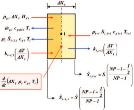
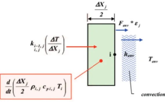
Figures 4-16 show the schemes used (Curry 1965) for each node, depending on the state and the conditions to which it may be subjected. Th ese fi gures also show the contributions of each phenomenon considered in the composition of the corresponding coeffi cients of the various equations of Eq. 17. Th e contributions marked with a red arrow provide energy to the node, whereas contributions marked with a blue arrow remove energy.
Figure 4. Nodal scheme – fi rst node: front surface.
Figure 6. Nodal scheme – state 2: mature char/reaction zone interface.
Figure 7. Nodal scheme – state 3: reaction zone.
Figure 8. Nodal scheme – state 4: reaction zone/ablative virgin material interface.
Figure 10. Nodal scheme – state 6: ablative virgin material/1st substructure material interface.
Figure 11. Nodal scheme – state 7: Jth substructure material.
Figure 12. Nodal scheme – state 8.1: Jth/Jth+1 substructure material without gap.
Each equation of Eq. 17 that constitutes the system of equations in Eq. 18 belongs to one of 13 types, as described in Eqs. 27-39. These equations refer to the corresponding number of schematizations assumed and described in Figs. 4-16.
Figure 14. Nodal scheme – state 8.3: fi rst node interface Jth substructure material with gap (radiation + convection).
Figure 15. Nodal scheme – state 9.1: last node Jth substructure material with adiabatic surface.
Figure 16. Nodal scheme – state 9.2: last node Jth substructure material with radiation and convection/cabin interior.
• Front surface node equation:
where the entering heat flux is given by Eq. 9. • State 1 equation:
(28)
(29)
(30)
(31) • State 2 equation:
• State 3 equation:
• State 5 equation:
(32)
(33)
(34)
(35) • State 6 equation:
• State 7 equation:
• State 8.3 equation: • State 8.2 equation:
(36)
(37)
(38)
(39) • State 9.1 equation:
• State 9.2 equation:
CASE STUDY
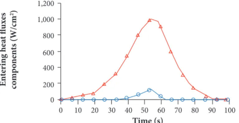
numeric programs. In particular, the verification generated extremely positive results and was performed by comparing the values found by Chen et al. (2006) using the FIAT code for the TPSs of the Stardust and Mars Exploration Rovers probes. The Stardust capsule’s re-entry under nominal conditions is presented in Figs. 17-20. The temporal trends of the main kinematic characteristics of the flight (altitude vs. time and velocity vs. time, respectively Figs. 17 and 18) and the convective and radiative components of the heat fluxes (Fig. 19) together with the temperature trend within the shield are presented, highlighting the zones where the ablative material is subdivided (Fig. 20). The pyrolysis reaction starts almost immediately and is followed by the beginning of the charring of the ablative layer (t = 6.5 s). At 20 s, the initial slow surface regression begins, and its intensity gradually increases. At t = 53.5 s, the maximum peak of the entering heat flux, which is the sum of the two convective and radiative components, is reached. At this time, the surface temperature reaches its maximum value of 3,740 K. Starting from a time of approximately 75.5 s, the maximum temperature of the shield no longer occurs on the surface: instead, from this moment on, the temperature trend has a maximum at points inside
Figure 17. Stardust capsule re-entry: altitude vs. flight time.
0 10 20 30 40 50 60 70 80 90 100 600 500 400 300 100 200 0 Time (s) Al ti tu d e (k m)
0 10 20 30 40 50 60 70 80 90 100
Convective Radiative 1,200 1,000 800 600 200 400 0 Time (s) E n te rin g he at fl ux es co m p o ne n ts (W/cm 2)
0 10 20 30 40 50 60 70 80 90 100 14 12 10 8 6 2 4 0 Time (s) V el o ci ty (k m/s)
Figure 18. Stardust capsule re-entry: velocity vs. flight time.
the ablative layer. At t = 83 s, the surface regression of the char layer stops, with a total thickness of consumed ablation material of 7.1 mm. Th e run then proceeds until 100 s, at which point the TPS mission is considered to be complete and the entering heat fl ow ceases. As for the superfi cial regression, its value measured at the capsule return was about 15 mm. However, this value takes into account the total erosion during the fl ight. Conversely, Covington et al. (2004), for values of maximum entering heat fl ux of 1,200 W/cm2, i.e., for nominal conditions equal to those hypothesized here, the estimate of the thickness of lost ablative material
is about 10 mm: value extensively within of the interval at 1 σ with respect to the result obtained by Mazzaracchio et al. (2010a) using this ablative model with a Monte Carlo simulation.
CONCLUSIONS
A numerical program was presented to solve the one-dimensional thermal problem for charring ablative materials. Th e results of the Stardust return capsule were presented as a case study. Th e results obtained show excellent agreement with similar literature
Figure 20. Stardust capsule re-entry: TPS temperature trend.
4,000 T em p er at ur
e (K) 3,000
2,000
1,000
0
0 10 20 30 40 50 60 70
t = 0.0s
Re-entry start 4,000 T em p er at ur
e (K) 3,000
2,000
1,000
0
0 10 20 30 40 50 60 70
t = 20.0s
Recession start T em p er at ur e (K) T em p er at ur e (K) 4,000 T em p er at ur
e (K) 3,000
2,000
1,000
0
0 10 20 30 40 50 60 70
t = 100.0s X (mm)
X (mm) X (mm) Re-entry end 70 70 4,000 T em p er at ur
e (K) 3,000
2,000
1,000
0
0 10 20 30 40 50 60 70
t = 6.5s
Charring start 4,000 T em p er at ur e (K) 3,000 2,000 1,000 0
0 10 20 30 40 50 60 70
t = 83.0s
Recession end, thickness 7.1mm
data obtained using industrial standard programs with high representativity like the NASA Ames Research Center’s “Fully Implied Ablation and Thermal” (FIAT) code for the TPSs.
REFERENCES
Chen Y-K, Milos FS (1999) Ablation and thermal analysis response program for spacecraft heatshield analysis. Journal of Spacecraft and Rockets. 36(3):475-483.
Chen Y-K, Milos FS (2000) Two-dimensional implicit thermal response and ablation program for charring materials on hypersonic space vehicles. AIAA Paper 2000-0206.
Chen Y-K, Milos FS (2005) Three-dimensional ablation and thermal response simulation system. AIAA Paper 2005-5064.
Chen Y-K, Squire T, Laub B, Wright M (2006) Monte Carlo analysis for spacecraft thermal protection system design. AIAA Paper 2006-2951.
Clark RK (1973) An analysis of a charring ablator with thermal nonequilibrium, chemical kinetics, and mass transfer. NASA TN D-7180.
Covington MA, Heinemann JM, Goldstein HE, Chen Y-K, Terrazas-Salinas I, Balboni JA, Olejniczak J, Martinez ER (2004) Performance of a low density ablative heat shield material. 37th AIAA Thermophysics Conference, Paper No. AIAA-2004-2273, June 28-July 1, 2004; Portland, Oregon.
Curry DM (1965) An analysis of a charring ablation thermal protection system, NASA TN D-3150.
Curry DM (1974) Two-dimensional analysis of heat and mass transfer in porous media using the strongly implicit procedure, NASA TN D-7608.
Ko L, Gong WL, Quinn RD (2007) Reentry thermal analysis of a generic crew exploration vehicle structure, NASA, TM-214607.
Landau HG (1950) Heat conduction in a melting solid, quarterly of applied mathematics 8(1):81-94.
Matting FW (1970) Analysis of charring ablation with description of associated computing program, NASA TN D-6085.
Marschall J, Maddren J, Parks J (2001) Internal radiation transport and effective thermal conductivity of fibrous ceramic insulations, AIAA Paper 2001-2822.
Mazzaracchio A, Marchetti M (2010a) A probabilistic sizing tool and Monte Carlo analysis for entry vehicle ablative thermal protection systems. Acta Astronautica 66(5-6):821-835. doi: 10.1016/j.actaastro.2009.08.033
Mazzaracchio A, Marchetti M (2010b) Coupled aeroassisted orbital plane change manoeuvre and thermal protection system optimisation, IAC-10-C2.7.4, 61st International Astronautical Congress, September 27-October 1; Prague, Czech Republic.
Mazzaracchio A, Marchetti M (2011) Spacecraft aerodynamics and heat shield characteristics impact on optimal aeroassisted coplanar orbital transfer, IAC-11-C2.7.9, 62nd International Astronautical Congress, October 3-7; Cape Town, South Africa.
Mazzaracchio A (2013) Heat shield mass minimization for an aerocapture mission to Neptune. International Journal of Aerospace Innovations 5(3-4):83-93. doi: 10.1260/1757-2258.5.3-4.83
Mazzaracchio A (2015) Flight-path angle guidance for aerogravity-assist maneuvers on hyperbolic trajectories. Journal of Guidance, Control, and Dynamics 38(2):2015:238-248. doi: 10.2514/1.G000670
Mazzaracchio A (2016) Coupled versus uncoupled optimal solution for thermal and dynamic problems in spacecraft atmospheric flight. World Journal of Engineering 13(1):53-60. doi: 10.1108/WJE-02-2016-006
Moyer CB, Rindal RA (1968) An analysis of the coupled chemically reacting boundary layer and charring ablator – Part II – Finite difference solution for the in-depth response of charring materials considering surface chemical and energy balances, NASA CR-1061.
Nathan RP, Bindu S (2005) Low temperature ablative heat shield for re-entry vehicles, AIAA Paper 2005-5063.
Pittman CM, Howser LM (1972) Numerical analysis of the transient response of an axisymmetric ablative char layer considering internal flow effects, NASA TN D-6895.
Roberts L (1958) A theoretical study of stagnation-point ablation, NASA TN 4392.
Swann RT, Pittman CM, Smith JC (1965) One-dimensional numerical analysis of the transient response of thermal protection systems, NASA TN D-2976.