Perspective’s Playful Parent
Ant´onio Ara´ujo∗Abstract
We explore conical anamorphosis in several variations and discuss its various constructions, both physical and diagrammatic. While exploring its playful aspect as a form of optical illusion, we argue against the prevalent perception of anamorphosis as a mere amusing derivative of perspective and defend the exact opposite view—that perspective is the derived concept, consisting of plane anamorphosis under arbitrary limitations and ad-hoc alterations. We show how to define vanishing points in the context of anamorphosis in a way that is valid for all anamorphs of the same set. We make brief observations regarding curvilinear perspectives, binocular anamorphoses, and color anamorphoses.
Keywords: conical anamorphosis, optical illusion, perspective, curvilinear perspective, cyclorama, panorama, D¨urer machine, color anamorphosis.
Introduction
It is a common fallacy to assume that something playful is surely shallow. Conversely, a lack of playfulness is often taken for depth. Consider the split between the common views on anamorphosis and perspective: perspective gets all the serious gigs; it’s taught at school, works at the architect’s firm. What does anamorphosis do? It plays parlour tricks! What a joker! It even has a rather awkward dictionary definition:
Anamorphosis: A distorted projection or drawing which appears normal when viewed from a particular point or with a suitable mirror or lens. (Oxford English Dictionary)
∗This work was supported by FCT - Funda¸c˜ao para a Ciˆencia e a Tecnologia, projects
But as often is the case, it turns out that the playful sibling has hidden depths and the serious sibling is hiding a weakness under a frown. We will play a few optical games with anamorphosis and in the process, clarify its relation with perspective.
Defining Anamorphosis
A machine with no visible effect
Picture a Rube Goldberg machine that performs no action at all. Anamor-phosis can be playfully defined as
the visual game of making nothing happen by purposefully elab-orate means.
Let me elaborate:
Definition: We say that two spatial objects1are anamorphically equiv-alent (or are anamorphs) with regard to a point O if they look the same when seen from O.
The first thing to note is that isn’t a mathematical definition since “look the same” is a statement about psychophysics. The only way to know if two things “look the same” is by presenting them to an actual observer in quick succession and check whether he notices the switch. Having said that, what do we know empirically about how an object relates to its anamorphs?
The following seems reasonable:
Principle of radial occlusion (RO): for an eye at a point O, points P and Q look the same if−OP =−→ −OQ.−→
This is not a trivial statement. It is not a statement about geometry, but a geometric statement about vision. The proof that it is not trivial is that it is, in general, false! It fails whenever reflection or refraction happen (Figure 1), and since refraction happens at our very eye (there’s a lens there!) then it is sure to always fail to some degree. But it works well enough to be a useful model of monocular vision under “default” conditions, or even binocular vision if distances are large enough.
1
Figure 1: Radial Occlusion failure by refraction at the interface of two optical media (e.g. water and air)—points A and B look the same when seen from O
but are not on the same ray from O.
When RO applies, this follows:
Proposition: Let O be a point. A spatial object X defines a cone CO(X) = {
−−→
OP : P ∈ X} with vertex at O, which we call the cone of vision of X from O. Two objects are anamorphically equivalent with respect to O if they define the same cone of vision from O.
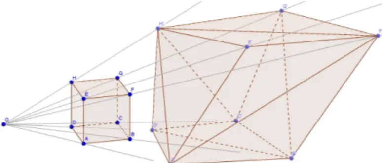
So, the objects in Figure 2 are anamorphs of each other, despite being quite different geometrically. No matter that they have different numbers of faces and edges, they define the same cone from O, and therefore look the same from that point.
Figure 2: A cube and its anamorph with regard to O.
In essence, RO identifies visual data with rays from O. Of course, rays from O and points of SO2 (the unit sphere around O) are the same thing. So, put in another way, X and Y are anamorphically equivalent if they have the same projection on the unit sphere by the map P 7→−OP /k−→ −OP k.−→
Any map f : R3 → R3 that preserves rays will transform any set into an
anamorph of itself; we call such maps anamorphic transformations.
The following is easy to show: If AB is a line segment and we freely slide A and B along they rays from O to get points A0, B0, then A0B0 is an anamorph of AB. If 4ABC is a triangle and we slide its vertices freely along their rays, we obtain an anamorph triangle 4A0B0C0 by joining the image points. We can obtain anamorphs of polyhedra in this way—just slide the vertices of a triangulation arbitrarily along their rays and join their images. By some adequate interpolation we can push and pull control points to get anamorphs of more complex objects in this way.
Since the whole point of RO is that distance from O is irrelevant, it is natural to think of pushing all points of an object X onto a two-dimensional compact surface S, to get a two-dimensional anamorph (a drawing) of X. By RO, CO,S(X) = CO(X) ∩ S is an anamorph of the set X ∩ CO(S) with
respect to O. We call it the conical projection of X onto S with respect to O. But we don’t call it the anamorphosis of X onto S just yet. We would like that to be a compact set, and we are missing its vanishing points.
Vanishing points of anamorphoses
We all know how vanishing points work in classical perspective: as a point travels along a line to infinity, the intersection of the visual ray with the projection plane tends to a limit point never actually hit, and that is what we call a vanishing point. We would like to avoid such talk as “going to infinity” and of projection planes since we’d like a definition that works for all anamorphs. The following notion of vanishing point depends only on X and O:
The space of rays from O inherits the topology of the sphere S2
O. Hence
we can speak of the topological closure of a set. Let Cl(Y ) denote the closure of a set Y . Then if X is a closed set, we say that Cl(CO(X)) is the
anamorphosis of X relative to O, and that VO(X) = Cl(CO(X)) \ CO(X)
are its vanishing points. That is, the vanishing points are those rays that we must add to the visual cone of X to make it closed. We identify the vanishing rays of CO(X) with the corresponding points in the sphere or in
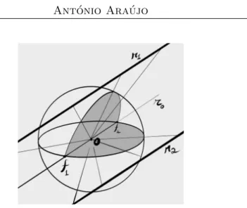
Figure 3: - Line r0is the translation of both r1and r2 to the origin. Its
intersection with the sphere obtains the vanishing points f1 and f2 common to
both lines. The images of r1and r2on the sphere are meridians that converge on
these vanishing points.
Given a compact surface S, we define the anamorphosis of X onto S with respect to O to be Cl(CO(X))∩S and its vanishing points to be V ∩S.
The vanishing points of a line on S will be those vanishing points of the line whose rays from O happen to intersect S. Hence, for instance, if S is a plane you will have either zero or one vanishing points. I will leave it to the reader to figure out what happens when S is a cylinder, cone, etc, but it should be obvious that for all surfaces, the images of parallel lines will still converge to those vanishing points actually represented on the surface. We notice that the anamorphosis of a closed set (say, a line) onto a compact surface will be a compact set. We can say that for the topologist, anamorphosis is a game of compactification of the visual scene.
Games with strings: D¨
urer machines running back
and forth
Anamorphoses onto planes
Let us now talk about how to actually draw anamorphoses.
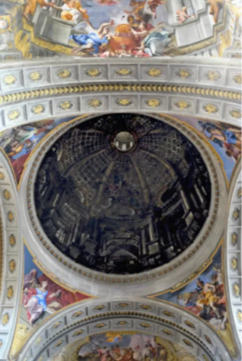
The most common examples of surface anamorphoses are projections onto planes. In Street art there’s a current of anamorphic drawings on pavements well exemplified by the chalk works of Julian Beever (Beever 2017). In illusionistic ceiling works, a magnificent exemplar is the false dome in the church of Sant’Ignazio in Rome painted in 1685 by Andrea Pozzo (Figure 4). Prevented from building the originally planned real dome, the Jesuits had Pozzo paint a plane anamorph of a dome on a stretched
canvas upon the church ceiling (Kemp 1990). It is a veritable masterpiece of optical illusion and an example of anamorphosis at its most practical in the service of architecture.
Figure 4: Anamorphic painting of a dome at the church of Sant’Ignazio in Rome. (photograph by the author).
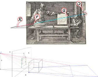
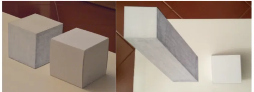
How do we go about constructing such plane anamorphs of a given object? The obvious way is to use a D¨urer machine (Figure 5): A thread fixed at O is led through a point P on an object and then transported to an equivalent point on a drawing surface. In D¨urer’s conception, the surface is a vertical plane and we get what is usually called a “perspective”. But we can run a D¨urer machine forward as well as backward, to make the thread hit the horizontal plane of the table, and then we obtain what is usually called a “plane anamorphosis” proper. But all three objects—the cube, its vertical and horizontal projections—are anamorphs, hence they look the same from O, and they are obtained by the same process, so one must stop and ask what the difference is, if any there be.
Obviously, horizontal/vertical is neither here nor there; planes do not relate to the viewer by the direction of the gravitational field! They relate to the viewer by taking the perpendicular to that plane through O, and the real difference is that the horizontal projection has been drawn at a larger angle to its perpendicular than the vertical one. This gives rise to larger “perspective deformations” on the horizontal anamorph—it gets
“stretched”. The same would have happened on the vertical plane by a different positioning of the cube. Perspective books will warn artists to keep their viewing angles small so as to avoid these deformations, and make it seem that somehow perspective fails for large angles.
Figure 5: Top: Perspective machine by Albrecht D¨urer (defaced by the author). Points P, Q, R are anamorphs for a viewer at O. Bottom: Construction of a
cube’s planar anamorphs on a vertical and on a horizontal plane.
I would point out that in Figure 5, the horizontal projection of the cube’s verticals is indeed very large, but then again, in the vertical picture, we have heavy compression (“foreshortening”) of the cube’s horizontals, which nobody complains about, and is seen as a feature rather than a breakdown of perspective. Perspective deformation is a misnomer, as both pictures are linearly deformed in whatever way is necessary to avoid angle deformations, which actually determine how things look from O. If I were to look at the vertical anamorph at a grazing angle it would look just as deformed (squashed) as if I was to look at the horizontal anamorph at a perpendicular, from which it looks stretched.
What we have here is what one might call a difference without a distinc-tion! And the difference is in the expectations on the part of the viewer. We naturally look at pictures on vertical planes by sticking our noses right in front of the point of interest (that is harder to do for pictures on the ground plane—then our feet get in the way!) so even an uninstructed viewer will look at the vertical drawing more or less from the right angle if not dis-tance; but show the same viewer the horizontal cube and he will have no clue on how to position himself. Then you can opt for two solutions: either mark the viewing spot clearly or let the viewer search for it. Andrea Pozzo took the former option in his church ceiling frescoes at Sant’Ignazio’s—a
big brass disc helpfully marks the viewing spot on the ground; the latter option is the soul of the parlour game that anamorphosis is well know for: the viewer is left to guess at the right spot, chasing a visual easter egg, and the fun is as much in finding it as in enjoying the grotesque deformations observed during the search. Artists avoid large angles, not because there is anything wrong with them, but so as to accommodate their unruly view-ers who will refuse to stand at the observation point of the picture; these ruffians will make a point of sticking their noses in front of every detail at the edge of the picture and then complain that it is “deformed”. To ap-pease them, the indulging artist will “correct” his plane anamorphosis into a “perspective”, by limiting the angle of view and “fixing” deformations with ad-hoc tricks such as turning ellipses into circles or hiding objection-able corners behind draperies, herding the eye of the visual illiterate to keep it from hurting itself. Pozzo would have none of this visual patronizing. He told his viewers exactly where to stand. Sure, he was helped by the fact that those noses had at least a bit of trouble reaching the ceiling, but still, he made no excuses for the spectacular collapse of the illusion when the viewer leaves the required spot. On the contrary, he argued—and having witnessed it on location, I agree—that this only makes the illusion more miraculous when the viewer achieves the right positioning.
So we see that not only can anamorphosis have a serious day job in architecture, but that it has a rather spotless geometric definition; and that what is usually called “perspective”, as actually practiced, is in fact a rather bastardized form of plane anamorphosis, marred by ad-hoc limitations and ill-defined fixes to cater to the nose-centric visual barbarian. Such is the true nature of the frowning, lesser sibling of anamorphosis. Always distrust a concept who puts on airs.
Let us leave plane perspective behind us and move to other games. The anamorphic surface S doesn’t have to be a plane, and D¨urer’s machine can be trivially subverted for use with curved surfaces.
In Figure 6 I used a thread to project a cube onto a union of a cylinder and a plane. Notice that the line segments that hit the cylinder become curved, and some of the connections are broken on the projected image. Anamorphs don’t have to preserve topology.
Figure 6: Anamorphosis of a cube onto the union of a cylinder and a plane, constructed by a D¨urer machine. Drawing by the author. Left: seen from O. Middle and Right: seen from two points away from O, showing deformations.
Now, after a while it gets cumbersome to use D¨urer’s machine. It re-quires a real object to start with, which hinders drawing from the imagi-nation.
We can solve this by abstracting the machine with an orthographic diagram, as seen in Figure 7. We start by describing our imaginary object in plan (top) and elevation (side) views as an architect would. Point O is split into its side view OSand its top view OT, and the thread is represented
by lines drawn from these points. Since the ground plane is perpendicular to the side view, we have a “true” intersection of the thread with the ground in this view (that is, the intersection of the projections is the projection of the intersections). Finding that intersection, we transport it to the top view and find its intersection with the image of the same ray. We thus obtain the anamorph of the object in top view; and we know that the place to see it from is with the eye over OT by a height equal to the length of the
segment GOS on the diagram.
Figure 7: Left: Plane anamorphosis of a U-shaped object built from orthogonal views. Right: The top view photographed from the observation point, at a height
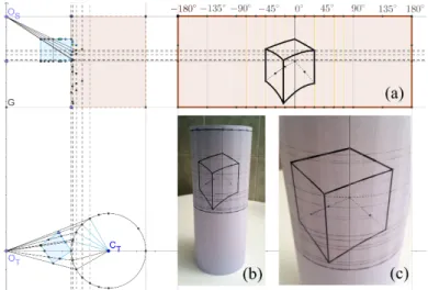
Of course, our virtual D¨urer machine works for curved surfaces as well. In Figure 8 we get an anamorphosis of a cube onto a cylinder. This time the “true” intersections are on the top view, as the cylinder is a ruled surface made up of vertical lines. These intersections are lifted up to the side view and from there transferred to the flattened cylinder on the right side of the picture. Notice that angles from O on the horizontal view transform linearly into lengths along the horizontal axis of the rectangle representing the unrolled cylinder. Since the cylinder is a developable surface, at the end of the process you can get the actual physical anamorph by simply cutting out the rectangle (a) and rolling/gluing it into an actual paper cylinder (b).
Figure 8: Anamorphosis of a cube onto a cylinder built from orthographic views. b) The rectangle in (a) is cut and rolled into a cylinder. c) the anamorph
of the cube seen from point O.
Things get more complicated when projecting onto a sphere. There are no true intersections either on top or on side view. But we can intersect with an adequate plane first and then find true intersection on that plane. I’ll let you figure it out. You can try this with cones and many other surfaces—it’s a nice exercise in descriptive geometry and it is my opinion that it would be a great way to teach that subject to young kids who otherwise find little motivation to learn it.
Again this visual game turns out to have very practical applications. In his perspective treatise (Pozzo 1700) Andrea Pozzo explains how to create an architectural illusion on an irregular ceiling such as the one he was painting at that time in the church of Sant’Ignazio. He used essentially the steps we performed: plan the architectural elements in orthographic views as if to build them; project them onto a plane anamorphosis; project the
plane anamorphosis onto the curved ceiling by transporting grids through a thread or through shadow projections.
Immersive Anamorphoses
If we now choose a surface S that surrounds the viewer, we can get an immersive anamorphosis. Conceptually, the simplest and most interesting example would be to place the viewer at the center of a sphere. Then the conical projection becomes trivial, as the projection surface identifies with the space of rays from O. Spatial lines project onto meridians and planes onto half spheres, and every line has exactly two vanishing points on the sphere.
Of course, in practice it is pretty hard to make a viewer float in the middle of a sphere, so half-measures may be called for—a dome will give an immersive experience from the zenith down to the horizon, in the style of a planetarium. If dimensions are large enough, a reasonable effect may be obtained by placing the viewer in a box. That is a device often used in computer graphics to simulate large landscapes. The advantage is that we are then limited to calculating five plane projections.
If looking up to the zenith is not required, a cylinder with the user at the axis affords a nice immersive anamorphosis. This is the principle of the cycloramas first displayed by Robert Barker in late 18th century England that enjoyed great popularity in the 19th century. From hundreds once in existence, some fourteen currently survive, some still on display, such as the panorama of the Battle of Waterloo painted by Louis Dumoulin in 1912, in a Belgian rotunda at the site of the famous battlefield, measuring 110 by 12 meters (Belgique 8), and the Gettysburg Cyclorama depicting Pickett’s Charge, painted by Paul Philippoteaux around 1883 and measuring 115 by 13 meters, currently on display at the Gettysburg Museum and Visitor Center (National Park Service 2017).
Our diagrams extend easily to the creation of cycloramas: in Figure 10 we see how a spatial line, pictured in plane and elevation, projects onto the unrolled cylinder—it is easy to see that the unrolled projection is a sinusoid. To get the cyclorama, just cut the rectangular drawing obtained and roll it into a cylinder.
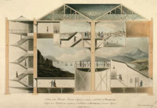
Figure 9: ‘Section of the Rotunda, Leicester Square’, aquatint by Robert Mitchell. (Mitchell 1801). Mitchell designed the Rotunda for Barker, who exhibited his panoramas on its the large cylindrical walls (Lee 1894). There were
two distinct cyclorama exhibitions inside the structure, separated by a dark corridor whose function was to clear the visual palate, so to speak, between the
two immersive experiences.
Figure 10: Projection of a line onto a cylinder with the viewer at the axis. On the right we obtain the projection on the flattened cylinder, which is actually a
cylindrical perspective. Cutting this rectangle and rolling it into a cylinder obtains the anamorphosis of the straight line, to be viewed from point O at the
axis.
Spherical anamorphoses with the viewer at the center are even easier to obtain, due to the natural isomorphism between rays from O and points on the sphere that we have already discussed. Every spatial line defines a meridian with exactly two vanishing points, which are found by trans-lating the line to O. A third point is always found by intersection with a coordinate plane. These three points determine the meridian.
Further anamorphic games
Anamorphosis, as far as we have considered it, has to do with apparent positioning of objects on the sphere of directions for a monocular viewer.
However, this is only a part of what constitutes a proper optical illusion. The following topics cannot be developed here but are perhaps worthy of brief mention.
Binocular vision
To deal with binocular vision it is enough to present each eye with its own anamorphosis, constructed from its specific point of view. Just do two different anamorphoses from two points OL and OR separated by the
interocular distance of the intended viewer. The hardest bit is to conceal from each eye the image intended for the other. The simplest way to achieve this is just to place a vertical barrier on the sagittal plane and confine each eye to its own half-space, but this can be awkward. A nice solution is to drawn the images in blue and red and then separate them by using old-fashioned anaglyphic red-blue 3D glasses (Figure 11). This way one can achieve a nice integration of the anamorph with its surroundings, in a sort of rudimentary “mixed reality”.
Figure 11: Anaglyphic anamorph of a cube, to be seen with red-blue 3D glasses. When the left and right eyes occupy the prescribed points OL and OR, a
wireframe cube will seem to pop out of the horizontal plane. Color anamorphosis
Strictly speaking, what we have been doing treats all objects as silhouettes, where a “point” is either there or not; this is fine for “wireframe” objects, but has no consideration for the color sensation that each point on the face of a solid causes on the viewer: whether it is bright or dark, what is its hue or saturation. This is a long subject that here will only be hinted at briefly. the simple case of a plane anamorphosis of a white cube (Figure 12). Suppose both the cube and the drawing are matte objects so they reflect light in proportion to the reflectance of the material and the cosine of the angle of incidence. Now, the angle of incidence will be different on each face of the cube, but the plane anamorph has only one face. So we must paint the several areas of the plane anamorph with a gray value corresponding to the face of the real cube it represents. That is, we must change the
reflectance in order to compensate for the angle of incidence. Obviously, the color anamorph will only work for the prescribed light source. So the light source L plays a contextual role analogous to the viewpoint O. We cannot speak of “an anamorph of X” but of an “anamorph of X with respect to the viewpoint O and the light source L”. More generally, one might consider one light source for each object. Say, I might have a tree under the sun that I want to recreate as a bunch of paint on canvas to be seen on a gallery under a lamp.
Figure 12: Color anamorphosis of a white cube. The shading has to be compatible with the prescribed light. This notion is not addressed by the basic
definition of conical anamorphosis. In this case an approximation was made to the value of each face, disregarding hue and saturation.
Obviously, unlike ordinary anamorphosis, color anamorphosis is often impossible to realize. It is only seldom that differences in illuminant, dis-tance and angle of incidence can be all compensated by manipulations of reflectance curves.
Curiously, it is still not as hard as it might be. Consider for a minute that anamorphosis works by exploiting a weakness of our visual system: its inability to judge distances, as expressed by the RO principle. Now, color anamorphosis is greatly aided by another weakness of our color perception: color metamerism, that is, the fact that there are many different spectral distributions that are perceived as the same color sensation by our visual system. Metamerism is what allows us to reproduce such a large part— though not all—of the space of colors by mixing only a few different inks on paper. Color mixing is a type of color anamorphosis—a mimesis of color sensations that only works for the specific light sources under which it was created. Although this dependency is of little concern for casual applications, specialist tasked with restoring paintings know well that a color match that is perfect under one illuminant may very well fail glaringly under another.
Other Perspectives
We have seen how plane perspective is, in principle, just plane anamorpho-sis and, in practice, plane anamorphoanamorpho-sis with ad-hoc “fixes”. Curvilinear central perspectives derive from anamorphosis too, in a slightly more com-plex way. We treat this formally in (Ara´ujo 2015), but to put it simply, a “central perspective” is a plane drawing obtained by first taking an anamor-phosis onto a surface S and then flattening it in some way. This flattening is an arbitrary device and, exactly as in cartography, can be chosen in many ways. For instance, cylindrical perspective is just a cylindrical anamor-phosis that is cut parallel to the axis of the cylinder and unrolled onto a rectangle isometrically. In fact, it corresponds to the drawing on the right rectangle of Figure 10—as that diagram actually constructs a cylindrical perspective first, that we then roll into a cylindrical anamorphosis. Other perspectives will not be so easily related to their anamorphoses. The sphere, for instance, is not a developable surface, so it cannot be flattened isometri-cally. In any case, we again find that central perspectives are anamorphoses followed by an ad-hoc step. As we explored in (Ara´ujo 2017), each central perspective is associated with a specific reading mode which always carries a layer of mediation and abstraction away from the mimetic immediacy of anamorphosis. The convenience of working on a plane must be bought with the loss of the illusionary effect of anamorphosis. That is what makes classical perspective special in the brood of central perspectives that arise from anamorphosis: that if we eschew the ad-hoc tricks of its trade, it preserves the anamorphic effect, as it is the one central perspective whose flattening is the identity map. In this sense, we find that anamorphosis is not perspective’s awkward sibling after all, but indeed its playful and fertile parent.
References
[1] [Ara´ujo 2015] Ara´ujo, Ant´onio. “A Construction of the To-tal Spherical Perspective in Ruler, Compass and Nail.” 2015. https://arxiv.org/abs/1511.02969.
[2] [Ara´ujo 2017] Ara´ujo, Ant´onio. “Topologia, Anamorfoses, e o besti´ario das Perspectivas curvil´ıneas.” Convocarte (Faculdade de Belas Artes da Universidade de Lisboa), no. 2/3 (2017): (to appear).
[3] [Beever 2017] Beever, Julian. Julian Beever’s Pavement anamorphoses. 2017. http://www.julianbeever.net/.
[4] [Belgique 2017] Belgique, Division du Patrimoine de la R´egion wal-lone de. Le Panorama de la Bataille de Waterloo, exemple parti-culi`erement significatif de “Ph´enom`ene de Panoramas”. April 2008, 8. http://whc.unesco.org/en/tentativelists/5364/ (accessed March 10, 2017).
[5] [Kemp 1990] Kemp, Martin. The Science of Art. New Haven and Lon-don: Yale University Press, 1990.
[6] [Lee 1894] Lee, Sidney (Ed.). Dictionary of National Biography. New York: MacMillan and co., 1894.
[7] [mitchell 1801] Mitchell, Robert. Plans, and views in perspective, with descriptions, of buildings erected in England and Scotland and also an es-say, to elucidate the grecian, roman and gothic architecture, accompanied with designs. London: Wilson & Co, 1801.
[8] [NPS 2017] National Park Service. “The Battle of Gettysburg in art”. 2017.
https://www.nps.gov/gett/learn/historyculture/gettysburg-cyclorama.htm (accessed March 10, 2017).
[9] [Niceron 1652] Niceron, Jean-Fran¸cois. La perspective curieuse, ou magie articielle des effets merveilleux. Paris, 1652.
[10] [Pozzo 1700] Pozzo, Andrea. Perspectiva pictorum et architectorum, vol 2. Rome, 1700.
Universidade Aberta, Lisbon, Portugal CMAF-CIO, Lisbon, Portugal
Research Centre for Arts and Communication (CIAC-UAb), Lisbon, Portugal