The use of inclined hemisphere projections for analyzing failure
mechanisms in discontinuous rocks
M.S. Lana
a,*, M.F.A. Gripp
ba
Department of Mining Engineering, University of Ouro Preto, Brazil b
Department of Mining Engineering, University of Minas Gerais, Brazil
Received 21 November 2001; accepted 29 July 2002
Abstract
This paper demonstrates the advantages of using inclined stereographic projections in kinematic analysis of rock blocks in discontinuous rock masses. Some examples of limiting cases are presented. The application of inclined projections is illustrated by its use in a mine slope in Brazil. It is clear from the discussion of these examples that inclined hemisphere projections provide better results than horizontal projections. It is also demonstrated that horizontal projections can lead to incorrect results in limiting cases.
D2002 Elsevier Science B.V. All rights reserved.
Keywords:Stereographic projections; Kinematic analysis; Failure mechanisms, single-plane sliding; double-plane sliding
1. Introduction
Stability analysis of rock blocks in discontinuous rock masses depends mainly on the spatial arrange-ment and strength of the discontinuities. The success of an evaluation of the stability of these blocks depends basically on the knowledge of these disconti-nuities and on the assessment of the failure mecha-nisms that can take place. All subsequent analysis, such as the stability analysis or the support system design, will be meaningless if the failure mechanisms are not well defined.
Stereographic projection methods are very useful for defining failure mechanisms in discontinuous rock masses. These methods have been widely used in many fields, such as structural geology, crystallogra-phy and rock mechanics. They are very functional for solving problems that require the measure of angular relations, with the advantage of simplicity. Moreover, they yield a clear representation of the spatial arrange-ment of the discontinuities, facilitating the under-standing of the problem.
Many authors have explained how to use horizon-tal projections to define failure mechanisms in jointed rock (Goodman, 1976; Hoek and Bray, 1981; Math-eson, 1983; Hudson and Harrison, 1997). These techniques are well understood and have been tradi-tionally applied to many projects.
In spite of the widespread use of horizontal pro-jections, there are some situations where they do not
0013-7952/02/$ - see front matterD2002 Elsevier Science B.V. All rights reserved. PII: S 0 0 1 3 - 7 9 5 2 ( 0 2 ) 0 0 2 0 3 - X
*
Corresponding author. Fax: +55-31-35591606. E-mail address:[email protected] (M.S. Lana).
provide clear insight on failure phenomena. In most of failure mechanisms involving discontinuities, there are at least three surfaces defining the potentially unstable blocks. These surfaces can be all disconti-nuities or not. One of them can be, for example, a tension crack in a slope or even a free additional face in an excavation. If horizontal projections are used in these cases, it will be impossible to consider all the planes that delimit the block because the analysis is limited to failure mechanisms involving only two discontinuities. The third plane causes no effect on the results of the analysis. It implies in adopting a simplified geometry of the potentially unstable block, leading to the assumption of arbitrary rules to define the failure mechanism, as it will be shown in this work.
This paper demonstrates that the alternative approach originally proposed byPriest (1980, 1985) to define failure mechanisms, based on inclined hemi-sphere projections, yields the best results. The aim of this work is to demonstrate the problems of using the conventional approach, based on horizontal projec-tions, in complex mechanisms that involve more than two discontinuities. It will be clear that the latter procedure can yield misleading results in some limit-ing cases.
Some examples of the application of the inclined hemisphere projection in kinematic analysis in a slope in Brazil are presented to show the accuracy of this approach.
Only sliding of rock blocks made up of three discontinuities will be considered in this paper to illustrate the differences between the use of horizontal and inclined hemisphere projections. Although this assumption is very limited, the analysis presented here provides strong arguments in favor of the use of inclined hemisphere projection methods in kinematic analysis.
2. The role of kinematic analysis in stability studies
Kinematic feasibility can be generally referred to as the freedom of rock blocks to move under the action of a set of forces. A kinematic analysis is the procedure for defining failure mechanisms through the use of stereographic projection methods. It is vital for analyzing the stability of blocks in a rock mass and
must precede any subsequent analysis. Once failure mechanisms are established, it is possible to perform a complete analysis of stability or to design an adequate support system for the loosened blocks.
Failure mechanisms in discontinuous rock masses are usually associated with the relative spatial position of the discontinuities and the excavation face. During geologic – geomechanical mapping of outcrops, and sometimes during the description of borehole data, it is possible to identify the orientation of the most relevant discontinuities. Other important features of the discontinuities, such as spacing, persistence and frequency, are also very important to define which discontinuities delimit potentially unstable blocks. Unluckily, these features are hardly mapped with the desired accuracy, even in outcrops or along the walls of underground excavations. Moreover, there is the problem of sampling bias imposed by the mapping of planar surfaces that can introduce errors during the measure of these variables, as discussed by Priest (1985)andGrossmann (1990) among others.
The difficulties associated with the mapping of discontinuities influence the data used in the kinematic analysis. In the majority of the situations, beyond the problem of sampling bias, sufficient data are hardly available because there are not many outcrops to get information. Some assumptions have been made to overcome these problems. It is common, for example, to assume that the size of discontinuities is sufficient to form rock blocks required for kinematic analysis. Another common assumption is that the average values of discontinuity orientations, measured in very large areas, are valid inputs for kinematic analysis. As a matter of fact, these values should be used only in case of lack of another option. Sometimes they must be used, for instance, in the beginning of a project because of the lack of surfaces to be mapped.
conspic-uous height and lateral extension, in such a way that the local variability of discontinuity orientations was considered in kinematic analysis. Failure mechanisms were analyzed using stereographic projection methods on small regions of the slope in order to detect this variability.
Blocks identified in kinematic analysis have the freedom to move. It does not mean that these blocks are unstable, since the discontinuity strength has not been considered yet. Only a complete stability anal-ysis can define if the block will move.
3. Inclined hemisphere projections: basic principles
When using inclined hemisphere projections, it is not necessary to set any arbitrary rules to identify failure mechanism, as it has to be done in the case of horizontal projections. Sliding of rock blocks, either single or double plane, takes place in the sliding surface associated with the maximum shear force, which requires the knowledge of the resultant force acting on rock blocks. Falling of blocks from an inclined excavation face is a failure mechanism that can only be defined if inclined hemisphere projections are used. It occurs when the resultant force does not keep any discontinuity plane in a state of compres-sion. This approach is much more reasonable than the analysis based on horizontal projections, as the failure mechanism is associated with normal and shear forces on sliding surface.
The relative positions of discontinuity planes on the excavation face define the physical existence of potentially unstable blocks. To find out the correct position of the blocks, it is necessary to establish the conditions for kinematic congruence. According to Priest (1985), the following conditions have to be met:
– the plane of projection must be parallel to the excavation face;
– the hemisphere of projection must be convex towards the free air of the face.
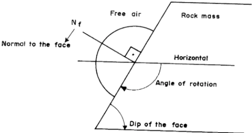
The conditions above are shown in Fig. 1 for a non-overhanging face like a slope. The axis of rota-tion corresponds to the strike of the face. The angle and the sense of rotation are established in a way to place the reference hemisphere on the same side of free air, as it can be seen inFig. 1. If a mistake is made in this procedure of constructing the inclined projec-tion, the block will not exist, as the planes will not converge to a point within the rock mass.
During the construction of the inclined projection, by rotating the excavation face and the discontinuity planes in the correct way, it is necessary to find out the position of the resultant force on the projection. The resultant depends on the various forces that act upon the block, like the weight of the block, the forces due to water pressures, etc. Methods for determining the resultant force have been explained byPriest (1985). The resultant force must be plotted on the inclined projection because failure mechanism depends on its orientation, sense and magnitude. The potential
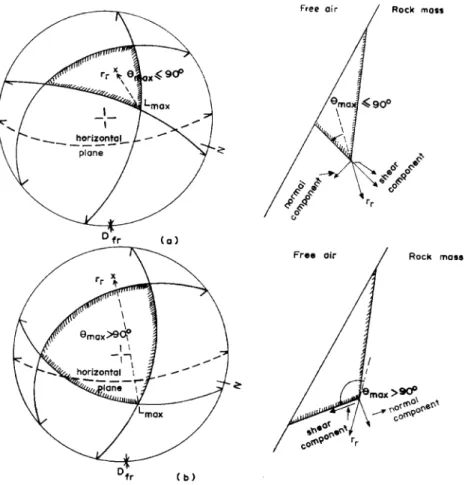
ing direction is given by a line located in one of the discontinuity planes where the shear component of the resultant force reaches its maximum value. It is represented inFig. 2bfor a block delimited by three discontinuities in a non-overhanging face. The poten-tial sliding direction is given by the line of intersection of two planes that delimit the block, a case of double-plane sliding. It can be seen fromFig. 2that this line makes the largest possible angle, measured internally on the projection, with the resultant force.
In a non-overhanging face, when the angle between the resultant force and the possible sliding direction is less than 90j, the block is stable, as it can be seen inFig. 2a. This block cannot move because the shear component of the resultant force is directed inwards towards the rock mass.
4. Problems associated with the use of horizontal projections
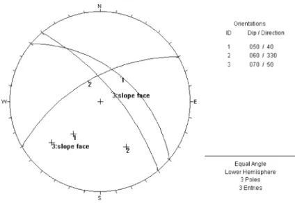
Many authors have been discussing procedures for defining the failure mechanism using horizontal pro-jections, especially in limiting cases, where single- or double-plane sliding can occur (Panet, 1969; Hock-ing, 1976; Goodman, 1976; Hoek and Bray, 1981; O¨ cal and O¨zgenoglu, 1997). One common approach is to consider that slide will take place on a single plane when the dip direction of the plane lies between the trend of the line of intersection of the planes and the dip direction of the slope face. This condition is shown in Fig. 3.
O¨ cal and O¨zgenoglu (1997) have also presented a procedure for distinguishing between double and
plane sliding adding one more condition to the approach represented in Fig. 3. These authors have considered that if the two dip directions of the planes involved lie between the trend of the line of inter-section and the dip direction of the slope face, sliding will occur on the plane that has a dip direction closer to the dip direction of the slope face. This plane itself exposes with its greater dip as well.
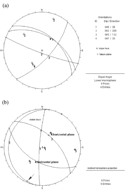
In limiting cases, the results of kinematic analysis can be different when using horizontal or inclined hemisphere projections, even though the block is subjected to simple gravitational loading, which is the situation usually considered when horizontal pro-jections are used. An example of such a situation is presented in Fig. 4. Three discontinuities have been identified through the zone of interest of a slope: plane 1, 039/45; plane 2, 200/82; plane 3, 132/65. The orientation of the slope face is 030/47.
In Fig. 4a, the horizontal projection of the lower hemisphere is shown. The discontinuities and the slope face are represented on the projection. The failure mechanism is single-plane sliding on plane 1 because the dip direction of this plane lies between the dip direction of the slope face and the trend of the line of intersection of planes 1 and 3.
In Fig. 4b, the inclined hemisphere projection on the slope face is shown, with the discontinuities plotted. The horizontal plane rotated to the slope face is also represented. It is important to notice that in
case of simple gravitational loading, the rotated pole of the horizontal plane is in the same position of the resultant force, the weight of the block. The block delimited by the three discontinuities is stable. The angle between the resultant force and any line in the boundary of the block is less than 90j, which means that the block is above the horizontal plane. Sliding on plane 1 is impossible because the block is stable. Moreover, the rotated line of maximum dip of plane 1, indicated by an arrow inFig. 4b, is outside the block made by the three discontinuities.
5. Application of inclined hemisphere projections for analyzing failure mechanisms in a slope
Lana (2000) studied the failure mechanisms in a large mine slope. Timbopeba Mine, an iron open pit mine, is situated in Minas Gerais, Brazil. The slope is very high (about 150 m at the time of its mapping). It has been excavated in a quartzite rock mass of complex geology. Failure mechanisms are controlled by discontinuity orientations and the orientation of the slope face in small domains, which were defined during the mapping phase. InLana et al. (1998), these mechanisms have been discussed. They have been defined for each domain referred to above.
A common situation in this slope was the presence of potentially unstable blocks delimited by three non-parallel discontinuities. In these cases, inclined hemi-sphere projections were used. During the analysis, it was considered that rock blocks were subjected to only gravitational loading.
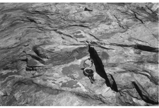
Limiting cases are very common. One of them is presented inFigs. 5 and 6. Three discontinuities have been identified through a small domain of the slope.
The most frequent discontinuity, which has been always found delimiting potentially unstable blocks in the slope, is the primary foliation. It has been identified in a large area in Minas Gerais known as Quadrila´tero Ferrı´fero. It has been called S1 by the geologists in Brazil. The other discontinuities were called F1and F2by the author of this study.
measured in the slide presented inFig. 5: S1, 029/35; F2, 180/77; F1, 308/75. The orientation of the slope face is 030/49.
S1is parallel to the slope face. It is in the plane where the compass lies inFig. 5. F1is on the right side of the slide inFig. 5and F2is on the left side.
Both double- and single-plane slidings are possible inFig. 6. The line of intersection of planes S1and F1 is almost in the same position of the line of maximum dip of S1. The inclined projection ofFig. 6allows the
visualization of the geometry of the potentially unsta-ble block on the slope face because it represents the view looking out towards free air along the normal to the rock face. So the positions of F1, F2and S1inFig.
Fig. 7. Horizontal projection of the slide inFig. 5 (DIPS 5.05, 2000).
6correspond to the reverse of the positions shown in Fig. 5as an image reflected by a mirror.
The horizontal projection of these discontinuities, which is presented in Fig. 7, also shows that it is a limiting case, as the line of maximum dip of S1 is almost coincident with the line of intersection of S1 and F1. Nevertheless, it is not possible to visualize the
correct position of the block in the slope face through this projection. Moreover, only the inclined projection is able to confirm that both double and plane sliding are possible, as it is more reliable than the horizontal projection.
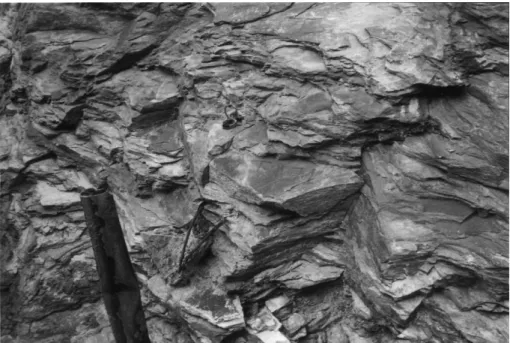
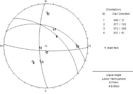
Another limiting case is presented inFigs. 8 and 9. Again, three discontinuities have been identified
Fig. 10. Horizontal projection of discontinuities ofFig. 9 (DIPS 5.05, 2000).
through the domain: S1, 021/40; F2, 182/77; F3, 268/ 72. The orientation of the slope face is 041/51.
S1lies on the plane of the slope face. F2is on the left side of the slides in the domain and F3is on the right side of the slides inFig. 8.
Again, both double- and single-plane slidings are possible in Fig. 9. The angle between the resultant force and the line of maximum dip of S1is equal to 129j, which is very close to the angle between the resultant force and the line of intersection of planes S1 and F3(125j). Another block might be formed, as it can be seen in Fig. 9, on the right side of the projection. In this case, double sliding on the line of intersection of planes S1and F2is the failure mech-anism. Plane sliding on plane S1 would not be possible because the rotated line of maximum dip of this plane is outside the potentially unstable block.
The geometry of the potentially unstable blocks in the domain can be visualized fromFigs. 8 and 9.
The horizontal projection of these discontinuities is presented inFig. 10. According to this projection, the failure mechanism is single-plane sliding on plane S1 as the line of maximum dip of S1lies between the line of maximum dip of the slope face and the line of intersection of planes S1and F3. It is not possible to see that this situation is a limiting case, as it is a typical case of plane sliding in the horizontal projection. Moreover, this projection does not show the two potentially unstable blocks that were identified inFig. 9.
Double-plane sliding is a common failure mecha-nism in this domain and it is a definitive argument for using inclined hemisphere projections in limiting cases.
6. Conclusions
Kinematic analysis of rock blocks in discontinu-ous rock masses is a very important step in the analysis of the stability of blocks in excavations. A mistake in this step influences the subsequent stabil-ity analysis. Inclined hemisphere projections warrant the accuracy of the kinematic analysis, as there is no need to assume any arbitrary rules to establish failure mechanism.
Limiting cases can be analyzed undoubtedly with the aid of inclined projections, as it has been clear from the discussion presented in this paper.
Inclined hemisphere projection methods are com-pletely general, independently of the type and the geometry of excavations and the kind of problem being analyzed. Overhanging and non-overhanging excavation faces, planar or not, can be considered. General polyhedral blocks can be analyzed.
Moreover, different types of failure mechanisms can be considered, such as falling of blocks, for example. General loading conditions are also easily introduced in the analysis.
References
DIPS 5.05, 2000. Plotting, analysis and presentation of structural data using spherical projection techniques, Rocscience. Goodman, R.E., 1976. Methods of Geological Engineering in
Dis-continuous Rocks. West, St. Paul.
Grossmann, N.F., 1990. Joint statistics—state of art and practical applications. International Workshop on Survey and Testing Methods for Discontinuous Rock Masses, Special Lecture, Japan.
Hocking, G., 1976. A method for distinguishing between single and double plane sliding of tetrahedral wedges. Int. J. Rock Mech. Min. Sci. Geomech. Abstr. 13, 225 – 226.
Hoek, E., Bray, J.W., 1981. Rock Slope Engineering. The Institu-tion of Mining and Metallurgy, London.
Hudson, A., Harrison, J.P., 1997. Engineering Rock Mechanics— An Introduction to the Principles. Pergamon, London. Lana, M.S., 2000. Estudo dos mecanismos de ruptura em taludes de
grande altura num macicßo rochoso de geologia estrutural com-plexa, PhD thesis, UFMG.
Lana, M.S., Gripp, M.F., Destro, E., Abib, M.M., Amaral, U., 1998. Failure mechanisms in mine rock slopes. Proceedings of the Fifth South American Conference in Rock Mechanics and Sec-ond Brazilian Conference in Rock Mechanics—SAROCKS’98, Brazil, pp. 365 – 370.
Matheson, G.D., 1983. Rock stability assessment in preliminary site investigations—graphical methods. TRRL report 1039. O¨ cal, A., O¨zgenoglu, A., 1997. Determination of sliding mode of
tetrahedral wedges in jointed rock slopes. Rock Mech. Rock Eng. 30 (3), 161 – 165.
Panet, M., 1969. Discussion on ‘‘Graphical stability analysis of slopes in jointed rock’’, by K.W. John. J. Soil Mech. Found. Div. Proc. ASCE 95 (SM2), 685 – 686.
Priest, S.D., 1980. The use of inclined hemisphere projection meth-ods for the determination of kinematic feasibility, slide direction and volume of rock blocks. Int. J. Rock Mech. Min. Sci. Geo-mech. Abstr. 12, 1 – 23.