2019
UNIVERSIDADE DE LISBOA
FACULDADE DE CIÊNCIAS
DEPARTAMENTO DE INFORMÁTICA
CAN FD: a communication network for future avionic systems
João de Sousa Alves
Mestrado em Engenharia Informática
Especialização em Arquitetura, Sistemas e Redes de Computadores
Dissertação orientada por:
Professor Doutor António Casimiro
Agradecimentos
Em homenagem ao Professor Doutor José Rufino, sem o qual a realização deste trabalho não teria sido possível.
Um agradecimento especial ao Professor Doutor António Casimiro que aceitou o desafio de me acompanhar e orientar rumo à conclusão desta dissertação.
i
Resumo
A presente dissertação incide sobre o protocolo de tempo real apelidado Controller Area Network with Flexible Data Rate, comumente designado como CAN FD, que opera ao nível da camada de Ligação de Dados do modelo OSI. Este protocolo é uma versão revista e melhorada (essencialmente em aspetos que envolvem a sua eficiência) do protocolo Controller Area Network (CAN), lançado em 1986 por uma equipa de engenheiros da Robert Bosch GmbH.
O desenvolvimento do protocolo CAN FD tem por base dois grandes objetivos: Em primeiro lugar, aumentar a velocidade de transmissão de dados na rede (de 1 para 15 Mbps); em segundo, permitir o envio de mensagens com um campo de dados superior ao do seu antecessor (de 8 para 64 bytes). No entanto, para conseguir implementar estas melhorias foi necessário introduzir alterações significativas à estrutura e funcionamento do protocolo original. Estas alterações tiveram vários tipos de impacto no protocolo, desde o tempo de transmissão de mensagens à forma como identifica e lida com erros. Isto faz com que a vasta literatura científica que atualmente acompanha o CAN (e que contribuiu grandemente para a confiança que existe em torno deste protocolo) não tenha necessariamente aplicabilidade direta ao CAN FD. Sobre esta perspetiva, a questão central passa por entender o impacto não óbvio que as alterações efetuadas têm, e o caminho para o conseguir determinar envolve, numa primeira instância, a reprodução de alguns dos estudos efetuados sobre o CAN.
O Controller Area Network, enquanto rede de tempo real, conheceu diversas aplicações, desde a indústria automóvel, para a qual foi inicialmente desenhado, até à engenharia aeroespacial e ao controlo industrial. Se tivermos de escolher um fator comum a muitos dos sistemas onde usualmente o CAN é implementado, poderíamos escolher a sua criticidade. Se um dos sistemas de suporte ao voo de um avião falhar, este pode afetar negativamente o piloto ou outros sistemas, induzindo-os em erro ou limitando as suas capacidades. Da mesma forma, uma falha numa linha de montagem industrial pode ter consequências desastrosas para todos os envolvidos. Neste sentido, é importante saber como os sistemas detetam e tratam erros e deve-se estudar o seu comportamento na presença e ausência destes erros. Se o máximo delay é o pior cenário de transmissão na ausência de erros para um protocolo como o CAN, o máximo delay somado ao tempo de identificação e recuperação de um erro dá-nos o pior cenário de transmissão na presença de um erro. Em sistemas críticos é esta última abordagem que devemos utilizar e acautelar. O conceito de inacessibilidade representa o tempo que uma rede de transmissão de dados está inoperacional (a recuperar de um erro) e mede-se desde o início da transmissão de uma
ii
mensagem, onde é identificado um erro, até ao retorno do protocolo ao normal funcionamento. No CAN, foi efetuado um estudo sobre os diversos tempos de inacessibilidade em função do tipo de erro que o protocolo poderia experienciar. No CAN FD, esse estudo está ainda por realizar e é esse o primeiro objetivo deste trabalho.
Como foi referido, as melhorias introduzidas pelo CAN FD obrigaram a certas readaptações no formato das tramas e em alguns mecanismos nativos do protocolo. Após um levantamento exaustivo destas modificações, conseguimos determinar qual o impacto direto que elas tiveram no tempo de transmissão de uma mensagem. Consequentemente, e tendo especial atenção a pequenas alterações introduzidas nos mecanismos de deteção e sinalização de erros do CAN FD, foi possível observar como este protocolo responde perante a existência de erros durante a transmissão de uma mensagem, derivando fórmulas matemáticas simples que permitem descrever o seu comportamento. Por sua vez, estas fórmulas matemáticas possibilitou-nos colocar um valor real sobre o tempo de inacessibilidade da rede quando esta é afetada por cada um dos tipos de erro definidos na especificação do protocolo. O resultado final deste estudo permitiu-nos fazer uma análise comparativa com os resultados de um outro, efetuado sobre o CAN original, uma vez que ambos partem dos mesmos pressupostos iniciais.
A simplicidade e “elegância” do CAN original sempre foram um fator de distinção relativamente a outros protocolos. Contudo, o processo de desenvolvimento do CAN FD trouxe consigo uma camada de complexidade adicional. Em alguns casos, as opções tomadas pela equipa de engenheiros responsável pelo desenho do CAN FD poderão ser vistas como polémicas ou discutíveis, muito devido à escassez de argumentos apresentados ou à ausência de estudos que as sustentem. Atentos a este facto, tomámos a decisão de mergulhar na cronologia de acontecimentos que levaram a cada uma das modificações observadas no CAN FD, com o intuito de nos pronunciarmos sobre se os meios utilizados realmente justificam os fins a que se propõe. A análise crítica e detalhada das modificações impostas pelo CAN FD é o segundo objetivo deste trabalho.
A pesquisa exaustiva das razões que antecederam algumas das alterações adotadas aquando do desenvolvimento do CAN FD levou-nos ao encontro de casos de escape em que a possibilidade de ocorrência de determinados erros mina toda a robustez anunciada do protocolo. Neste documento fica latente que a correção deste tipo de situações foi uma das prioridades da equipa por detrás do CAN FD, não tivesse a sua correção o impacto que teve no protocolo. Curiosamente, durante este processo de indagação acabámos por tropeçar num novo tipo de erro que afeta todas as versões do protocolo (CAN e CAN FD). As condições necessárias para a sua emergência e a forma como este afeta as transmissões de dados envolvem a conjugação de vários fatores, o que, hipoteticamente, diminui a probabilidade de observarmos a sua ocorrência num cenário de implementação real. Não obstante, existe validade teórica que suporta a sua existência e, como tal, deve ser identificado e comunicado. A explicação de como este erro ocorre e de quais as consequências que pode encerrar é o último tema abordado nesta dissertação.
iii
v
Abstract
The present dissertation focuses on the real-time protocol Controller Area Network with Flexible Data Rate, commonly referred to as CAN FD, which operates at the level of the Data Link layer of the OSI model. This protocol is a revised and improved version (essentially in terms of efficiency) of the Controller Area Network (CAN) protocol, launched in 1986 by a team of engineers at Robert Bosch GmbH.
The development of the CAN FD protocol is based on two main objectives: First, to increase the speed of data transmission in the network (from 1 to 15 Mbps); second, to allow messages to be sent with a data field higher than its predecessor (from 8 to 64 bytes). However, in order to implement these improvements it was necessary to introduce significant changes to the structure and operation of the original protocol. These changes had several types of impact on the protocol, from the time of message transmission to the way it identifies and handles errors. This makes the vast scientific literature that currently accompanies CAN (and which contributed greatly to the confidence that exists around this protocol) does not necessarily have direct applicability to the CAN FD. On this perspective, the central issue is to understand the non-obvious impact that the modifications have, and the way to determine it involves, in a first instance, the reproduction of some of the studies carried out on CAN.
The Controller Area Network, as a real-time network, has seen a variety of applications, from the automotive industry to which it was initially designed, to aerospace engineering and industrial control. If we have to choose a factor common to many of the systems where CAN is usually implemented, we could choose its criticality. If one of the flight support systems of an airplane fails, it may adversely affect the pilot or other systems, misleading them or limiting their capabilities. Likewise, a failure in an industrial assembly line can have disastrous consequences to everyone involved. In this sense, it is important to know how systems detect and treat errors and to study their behavior in the presence and absence of these errors. If the maximum delay is the worst transmission scenario in the absence of errors for a protocol like CAN, the maximum delay added to the time for identification and recovery of an error gives us the worse transmission scenario in the presence of an error. In critical systems is this last approach that we must use and caution. The concept of inaccessibility represents the time that a data transmission network is inoperative (to recover from an error) and is measured from the beginning of the transmission of a message, where an error is identified, until the return of the protocol to normal operation. In the CAN, a study was performed on the various inaccessibility times due to the type of error that the
vi
protocol could experience. In CAN FD, this study is still to be carried out and is the first objective of this work.
As mentioned, the improvements introduced by CAN FD have forced some adaptations in the format of the frames and in some native mechanisms of the protocol. After an exhaustive survey of these changes, we were able to determine the direct impact they had on the transmission time of a message. Consequently, and with special attention to small changes introduced in the detection and signaling mechanisms of the CAN FD protocol, it was possible to observe how it responds to the existence of errors during the transmission of a message, deriving simple mathematical formulas that allow the description of its behavior. In turn, these mathematical formulas permitted to place a real value on the network inaccessibility time when it is affected by each one of the error types defined in the protocol specification. The final result of this study allowed us to make a comparative analysis with the results of another one, carried out on the original CAN, since both start from the same initial assumptions.
The simplicity and "elegance" of the original CAN protocol has always been a distinguishing factor compared to others. However, the CAN FD development process has brought with it a layer of additional complexity. In some cases, the options taken by the team of engineers responsible for the design of the CAN FD may be seen as controversial or debatable due to the lack of arguments presented or to the lack of studies that support them. With this in mind, we decided to investigate the events that led to each of the modifications observed in CAN FD, in order to decide whether the means really justify the purposes. The critical and detailed analysis of the modifications imposed by the CAN FD protocol is the second objective of this work.
The exhaustive research of the reasons that preceded some of the changes adopted during the development of the CAN FD led us to find escape cases in which the possibility of occurrence of certain errors undermines all the announced robustness of the protocol. In this document it becomes clear that the correction of this type of situations was one of the priorities of the team behind CAN FD. Curiously, during this examination process we ended up stumbling over a new type of error that affects all versions of the protocol (CAN and CAN FD). The conditions required for its emergence and the way it affects data transmissions involve the combination of several factors, which, hypothetically, decreases the probability of observing its occurrence in a real implementation scenario. Nevertheless, there is theoretical validity that supports its existence and, as such, it must be identified and communicated. The explanation of how this error occurs and of what consequences it may contain is the last topic addressed in this work.
viii
Index
1.
Introduction ... 1
2.
State of the Art: the CAN Protocol ... 5
3.
CAN FD Protocol Description and Behavior ... 11
3.1.1
Message transmission and codification ... 11
3.1.2
Message prioritization ... 13
3.1.3
Message validation ... 14
3.1.4
Fault confinement and node state ... 15
3.1.5
ISO CAN FD protocol... 15
3.2.1
CAN - Data and remote frames ... 16
3.2.2
CAN FD - Data frames... 17
3.2.3
CAN and CAN FD evaluation ... 18
4.
CAN FD Inaccessibility Characteristics ... 21
4.1.1
Bit Errors ... 22
4.1.2
Bit Stuffing Errors ... 22
ix
4.1.4
Form Errors ... 24
4.1.5
Acknowledge Errors ... 25
4.1.6
Consecutive and Successive Errors ... 25
5.
CAN FD Development Analysis ... 32
5.1.1
Control Bits ... 33
5.1.2
Dual CRC polynomial ... 33
5.1.3
Dynamic and Fixed Stuff Bits ... 34
5.1.4
Fixed Stuff Bits error categorization ... 35
5.1.5
Dynamic Stuff Bits into CRC... 36
5.2.1
Missing evidencies ... 38
5.2.2
Article overview ... 41
5.2.3
Adopted solution – Yet another modification ... 43
5.2.4
Related concerns ... 44
5.2.5
New fault type – Combination of the previous cases ... 46
6.
Further Work ... 50
x
List of Figures
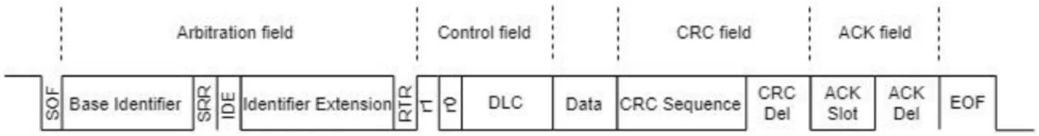
Figure 2.1 – CAN Data Frame (Extended Format) ... 6
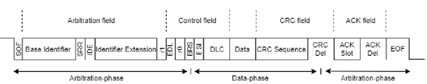
Figure 3.1 – CAN FD Data Frame (Extended Format) ... 12
Figure 3.2 – CAN FD Data Frame (Extended Format) with transmission phases ... 16
Figure 3.3 – CAN, CAN FD and ISO CAN FD frame duration ... 20
Figure 4.1 – CAN, CAN FD and ISO CAN FD base format inaccessibility duration ... 29
Figure 4.2 – CAN, CAN FD and ISO CAN FD extended format inaccessibility duration 29 Figure 5.1 – Undetectable synchronization fault due to the dual data rate ... 38
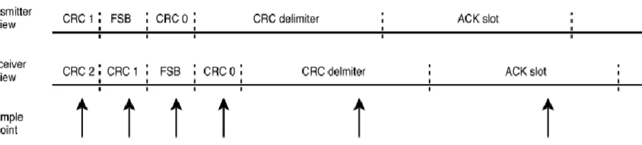
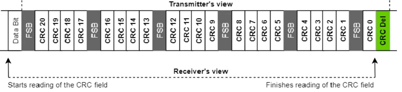
Figure 5.2 – Misaligned receiver view over the CAN FD 21-bit CRC field ... 42
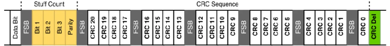
Figure 5.3 – ISO CAN FD 21-bit CRC field ... 43
Figure 5.4 – Hardware approach to CAN CRC vulnerability ... 46
Figure 5.5 – Software approach to CAN CRC vulnerability ... 46
xii
List of Tables
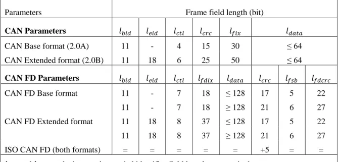
Table 3.1 – CAN, CAN FD and ISO CAN FD frame field length ... 19 Table 3.2 – CAN, CAN FD and ISO CAN FD frame duration ... 19 Table 4.1 – CAN, CAN FD and ISO CAN FD inaccessibility duration ... 28
1
1. Introduction
Context
The present thesis presents, studies and evaluates the real-time network protocol – Controller Area Network with Flexible Data-Rate [2], commonly known as CAN FD, by critically analyzing some of its structural characteristics and its behavior under normal and abnormal operation conditions, focusing on determinant real-time networks properties like reliability and robustness, and others like performance. This work is motivated by the CAN FD release and attempts to shed light on yet uncovered aspects of this new protocol.
CAN FD was developed to improve some of the features in the original Controller Area Network [1] – a protocol developed in the year of 1986 by Bosch engineers and first implemented in 1988. Classical CAN was specifically designed to be used in the automotive industry. Its main function was to enable reliable real-time communication between car components. Later, it was found to be useful in many other domains, such as industrial control and aerospace engineering, due to its strong reliability and robustness properties, low implementation costs and relatively small implementation complexity. All this upsides contributed to a wide dissemination, which gave notoriety to the CAN protocol during many years. However, the same characteristics that seemed reasonable in 1980’s – data rates up to 1 Mbps and data payload up to 8 bytes - are hardly sufficient to face the current market needs, where information volume and system performance are increasingly determining factors. Even though performance is not what defines a real-time system (but timeliness and predictability are), neglecting it may call into question its overall acceptance. For this reason, Bosch put together a team in 2011 with the task of creating a new protocol that enables the transmission of larger data payload messages, at a higher rate, while maintaining the advantages that made CAN a successful network protocol in the first place. In 2012, the specification of the new Controller Area Network with Flexible Data rate was released to the public [2]. This publication uncovered a protocol which can be 15 times faster than CAN, supports an 8 times larger payload while, allegedly, maintaining the same reliability and robustness. This work addresses, in part, the mechanisms utilized by CAN FD designers to guarantee the above properties, in order to test their efficiency and applicability.
2
Motivation
The Controller Area Network protocol has been the subject of a profound study over time. Since its foundation, various aspects of the protocol have been addressed and evaluated in a way that it has gained the overall acceptance and appreciation of the scientific community. All this work contributed for a vast understanding and knowledge of CAN network. Nowadays, with the development and release of CAN FD and considering the profound changes in fundamental operation characteristics to which the protocol was subject, the same issues that arose over the original protocol become once more relevant and must be addressed, in order to determine if the existent scientific research is valid and applicable to the new protocol or, on the contrary, must be revised.
In addition to this discovery process, there are pertinent questions that are worth answering, concerning the transformation process that culminated in the deployment of CAN FD and later in the ISO CAN FD:
Is there a pertinent reason behind the changes made during the passage from CAN to CAN FD and do they all serve the intended purpose?
Has the overall network performance improved substantially? What are the costs of this enhancement?
Does CAN FD deliver the same reliability and robustness properties of its predecessor?
Objectives
A CAN FD network is exposed to a series of events that can lead to a malfunction in its normal operation. The origin of such errors may range from electromagnetic interference (EMI) to a failure in network components. These errors can have a permanent effect, effectively disabling all network communication (i.e. damaged media bus), or a transient one. In the second case, the network is only unable to operate during the time frame in which the error occurs, is treated and gets recovered from. This type of incident is common and can happen several times during network operation, depending on internal factors like the chosen physical media or external ones, such as the environment in which it is deployed. Even though some networks can operate under frequent and long communication glitches, in CAN FD real-time behavior is expected. This often means high predictability and timeliness and gets increasingly important if we aim at hard real-time implementations. As such, the periods in which the network is inoperative must be analytically studied and measured in a way that they can be accounted for when designing this type of systems. This type of study was done over the original CAN protocol. However, the new features introduced by CAN FD make the revision of this topic mandatory.
Additionally, a major concern of the Bosch CAN FD development team was to endow the new protocol with at least the same error detection capabilities than its predecessor, since the
3
enhancements made to the new version forced the redefinition of some of its core mechanisms and the alteration of the frame structure itself. A specific study on these changes and on their impact over the mechanisms that guarantee the frame’s integrity is also under the scope of this work.
Given the above, the objectives of the work presented in this thesis are defined as follows:
Determine the changes made to the CAN protocol, with special emphasis in the error detection and error handling mechanisms;
Understand and modulate the behavior of CAN FD in the absence and presence of errors;
Derive the CAN FD transmission times in the absence and presence of errors and analyze the differences with respect to CAN;
Review and critically assess the groundwork that support each of the changes made to the CAN protocol.
Contribution
This thesis contributes to a better understanding of the CAN FD protocol in two distinct ways. First and foremost, the frame transmission times of CAN and CAN FD, in the absence of errors, are derived and calculated. This study, which focuses purely on efficiency, provides the bases for a more profound examination of the protocol behavior in the presence of errors, which is also part of this work. A subset of equations, one for each error type, supports the calculation of the time taken by a node in a CAN FD network to recover from an erroneous transmission and proceed with network operation. In sum, the first part of this thesis concentrates on the frame transmission time and on the error detection and recover mechanisms, comparing and evaluating the results against the same aspects of the previous protocol.
Secondly, the curtain that covers the reasons behind every transformation (made upon the passage from CAN to CAN FD and to its standardization) is raised and the fundaments that support them revealed. Here, a balancing exercise is made considering the benefits that these changes bring and the problems they carry. During this analysis we also encountered some inconsistencies in the work developed by Bosch engineers and the ISO task force that are here reported. Furthermore, the result of this second line of work is the discovery of a new fault type, which affects all versions of the protocol and was not, to this day, accounted for in related work.
Structure
The first part of this work presents CAN state of the art. Chapter 3 provides an overview over CAN FD structure and operation (determining its transmissions times) and identifies the differences between the two protocols. In chapter 4 we extend a study made over the original
4
CAN protocol to CAN FD, which considers network behavior in the presence of errors and, analytically, derive equations that measured the time periods in which the network is unable to operate (inaccessibility periods). In chapter 5 we make a detailed analysis of the changes to which the protocol was submitted to, giving a straightforward answer to how and why they were made and objectively identifying advantages, disadvantages and how they could be made differently. Finally, chapter 6 points out some challenges to be addressed as further work.
5
2. State of the Art: the CAN Protocol
The evaluation of CAN FD operation, in a more general sense, and of its new functionalities in relation to CAN is one of the purposes of this work. To accomplish this objective, it is essential to accurately describe the original protocol so that we can fully understand it before extending our analysis to the new version.
The Controller Area Network is a multicast, multi-master serial bus, with a deterministic collision resolution scheme. The transmission medium is composed by a twisted pair of wires. A node is a station that sends and receives messages through the bus. A message is composed by data and sent as a sequence of bits. Each bit is sequentially transmitted by setting the bus level (voltage on the wires) to one of two possible values: Dominant (logical 0) and Recessive (logical 1), which is also the state of an idle bus. Dominant values always overwrite recessive ones. This means that if a node sends a dominant bit to the bus and, at the same time, another node sends a recessive one, only the dominant state will be visible on the network. This characteristic is exploited during prioritization of messages – arbitration in CAN – to allow a non-destructive collision resolving scheme.
Bosch published several CAN specifications, being the last one CAN 2.0, which came out in 1991 [1]. It is composed by two parts: A and B, which respectively define a base frame format and an extended one, latter created to expand the upper limit of active nodes in a network at a certain point. For the sake of simplicity, the analysis of the CAN protocol will be divided into the following sections:
Message transmission and codification;
Message prioritization;
Message validation;
Fault confinement and node state.
Message transmission and codification
Application data is encapsulated in a CAN frame. We refer to CAN frames as messages. CAN frames respect a well-defined format, with several frame fields that allow receiving nodes to interpret the encapsulated application data and check the integrity of the received frame. A data frame can be transmitted in different formats. The latest specification of the CAN protocol [1], defines two distinct frame formats:
CAN base format;
6
The structural difference between the two consists of an augment in the arbitration field, from the base format to the extended one. Functionally, there is an important distinction, because it determines an augment in the available frame identifiers which, in turn, are uniquely used to identify every data frame in the network.
In addition to the transmission of application data, a node may also need to send CAN frames, for instance to signal an error condition such as the reception of a corrupted frame. Therefore, the following 4 types of CAN frames are defined:
Data frames – to transfer data between nodes;
Remote frames – to request the transmission of data by other nodes;
Overload frames – to delay the transmission of a frame;
Error frames – to signal the detection of an error.
A data frame is the message that carries the actual information. It encompasses the following fields in sequence:
Start of Frame (1 bit) – It is the first bit to be transmitted and marks the start of a new frame.
Arbitration Field (12 bits in base format and 32 in extended format) – It is composed by
the Identifier, which is unique for every data frame and determines its priority in the network, and by the RTR (remote transmission request) bit, which differentiates a data frame from a remote frame. If the RTR bit is transmitted dominant, the receiver will interpret it as a data frame. Otherwise, it will be considered a remote frame. Furthermore, the extended frame format comprises a longer Identifier field (29 bits instead of 11) and two additional bits – The SRR (substitute remote request) and the IDE (identifier extension) bits – which, respectively, substitute the RTR bit in the base format and indicate the format in which the frame is being transmitted. The values are dominant for standard format and recessive for the extended one.
Control Field (6 bits) – The control field contains the DLC (data length code) and two
independent bits. The DLC is 4 bits long and indicates the total length of the frame’s data field. The meaning of the two other bits differs from one format to the other. In the extended format both bits are reserved for further expansion and, as such, not used by the protocol. However, in the base format one bit is a reserved bit while the other one is the IDE bit. Notice that this is the same bit than the one presented above (in the arbitration field) for the extended format.
7
Data Field (up to 64 bits) – It is the actual data to be transferred. That is, the information
that the application wants to transmit.
CRC Field (16 bits) – The CRC (cyclic redundancy check) field contains a 15 bit CRC
sequence, used to check frame integrity, and a 1 bit CRC delimiter. The CRC sequence is the result of multiple XOR operations between a predetermined polynomial and the SOF, arbitration, control and data fields. Receivers also calculate the sequence themselves to check if the frame is error free. As to the CRC delimiter, it is always transmitted with recessive value.
ACK Field (2 bits) – The acknowledgement field is made of an ACK slot and an ACK
delimiter. A receiving node signals a successful message reception by means of a dominant bit during the ACK slot. Otherwise, it sends a recessive bit to the bus. During this time, the transmitter listens to the transmission channel. Alike in the CRC field, the ACK delimiter ends the ACK field and is transmitted with recessive value.
End of Frame Sequence (7 bits) – Made of seven consecutive recessive bits that end every
data frame.
The remaining three frames types are characterized as following:
Structurally, a remote frame is almost identical to a data frame. The difference between the two is that a remote frame does not transport any information (there is no data field).
Overload frames are composed of two fields: an overload flag with 6 dominant bits and an overload delimiter with 8 recessive bits. They are transmitted between data and remote frames to extend the intermission field.
An error frame also consists of two fields: an error flag with 6 bits of the same level (all recessive or all dominant) and an error delimiter with 8 recessive bits. It is triggered every time a node detects an error condition in the network. Once an error frame is issued by a node it eventually becomes visible to all other nodes in the network. Consequently, they abort their current transmission and emit themselves other error frames. This frame type serves the purpose of keeping the network consistent by forcing all nodes to accept or discard a message.
Messages in CAN are coded by the non-return-to-zero binary mechanism. This means that the bus is always in one of two possible states: recessive (when transmitting a ‘1’ bit) or dominant (when transmitting a ‘0’ bit). Given that, nodes are only able to synchronize themselves with others when they see a change in the bus level. If a transmitter sends a continuous sequence of bits of the same value, there is no opportunity for synchronization. If this sequence is long enough, clocks in two different nodes may drift from one another, causing distinct readings of the same bit stream (missing or doubling a bit). To overcome this problem and guarantee synchronization within the network, additional measures are considered in the CAN protocol.
8
The bit stuffing technique is one of those measures. In data frames and until the end of the CRC sequence, after every five consecutive bits of identical value an additional one, of opposite polarity, is inserted into the bit stream (stuff bit). From the receiver side, the bit following those five bits is interpreted as a stuff bit and consequently discarded. This is a way for the protocol to provide sufficient synchronization points between transmitter and receivers, while adding a small overhead to the network.
In a CAN network there is a 1Mbps data rate limit, introduced into the protocol by design. This bound applies to every frame type and can take a lower value depending on the length of the network (larger networks imply a lower data rate).
Message prioritization
At the beginning of every frame there is an identifier field, which determines its priority on the network. All nodes with messages waiting for transmission start a transmission by sequentially sending the first bits of their frames into the bus. At this point two different scenarios are possible: 1. A node sends a dominant bit and reads a dominant bit from the bus (as it will always do in the absence of errors). In this case it carries on with the transmission and sends the next bit.
2. A node sends a recessive bit and reads a dominant value from the bus. This means that another node is attempting to send a message with a higher priority and consequently it aborts.
By the end of this process, the node sending a frame with the lowest valued identifiers, wins arbitration, as it becomes the only transmitter, and simply carries on with the message diffusion. All other nodes turn into receivers, which are synchronized with the transmitter. Furthermore, messages that have lost the arbitration process are scheduled to be tentatively retransmitted after the full reception of the current message in the bus. Nondestructive arbitration is one of CAN’s fundamental characteristics for it allows the protocol to resolve collisions without wasting network bandwidth.
Two frames can have the same identifier if, and only if, one is a data frame and another is a remote frame. In such cases the RTR bit, which is part of the arbitration field, will force the nodes sending the remote frame to abort its transmission, since it goes with recessive value in remote frames and with dominant value in data ones. This guarantees that data frames have precedence over remote ones.
Message validation
Usually, CAN networks operate in environments with a high degree of electromagnetic interference which can cause the corruption of bits in the bit stream, by altering the bus level.
9
These kinds of errors have a determining effect on message integrity and, thereby, must be controlled. Moreover, faulty components may also undermine network operation by invalidating correct messages or transmitting erroneous ones. To impede such events from causing a malfunction or even disabling the network, a set of message validation mechanisms were introduced in CAN.
Different error detection mechanisms are put in place depending on whether a node is sending or receiving a message. These errors are then categorized according to its origin, enabling a better overall comprehension of network behavior in the presence of faults.
Error detection
When a transmitting node is sending a frame through the bus, it monitors its state after every transmitted bit. Should a transmitting node detect a deviation between the sent and observed value (e.g. sends a recessive bit and reads a dominant one from the bus) it will interpret it as a bit error. There are, however, two exceptions to this rule:
1. During the arbitration phase, when nodes compete for bus access. In this case, if a node sends a recessive value and reads a dominant one it aborts transmission.
2. During the ACK slot, where receivers have to tell the transmitter if the message was correctly received (by means of a dominant bit) or not (by a recessive bit).
Additionally, a recessive level during the ACK slot means that no receiving node correctly perceived the message, meaning that an error has occurred. Such cases are classified by transmitters as ACK errors.
From the receiver’s perspective, there are other conditions that indicate the existence of an error: Certain frame fields respect a pre-determined fixed format and are always transmitted with the same value. As so, a violation of this rule represents an incoherence in the network and is seen by receivers has a format error. Furthermore, the CRC sequence allows receivers to check for frame integrity. Should the result of this mechanism deviate from the expected value, the receiving node will comprehend it as a CRC error. At last, a node is in the presence of a stuff
error whenever there is a violation to the bit stuffing rule, that is, it reads from the bit stream
more than five consecutive bits of equal value (e.g. 6 dominant bits).
Error signaling
Every time a node detects an erroneous message it has to inform the rest of the network by means of an error frame. In most cases this signalization begins at the bit that immediately follows the detection. However, in the case of CRC errors, it only starts after the ACK delimiter.
Furthermore, error frames were projected to violate bit stuffing rules. Thus, every node listening to an error frame transmitted into the bus will also start the transmission of one of their
10
own. This is a way of guaranteeing that error frames are eventually perceived by all nodes in the network.
Fault confinement and node state
The behavior of a CAN node varies according to its internal state which, to some extent, is determined by the actions it has been taking on the network. As such, there are three possible node states:
Error Active: The node takes part in bus communication. When it detects an error it issues an error active flag.
Error Passive: The node takes part in bus communication but, after a transmission, it waits before initiating a new one (thus giving precedence to error active nodes).When the node detects an error issues an error passive flag.
Bus-off: The node is impeded to take part in bus communication.
State assignment is an easy way of limiting the action of a faulty node in the system. Node internal counters keep track of their own number of identified errors. An upper bound is defined (during network configuration) for the maximum number of identified errors before a node categorizes itself as error passive or bus-off. The logic in this mechanism is that if a node is identifying an abnormal number of errors, maybe their source relies in itself and, as so, diminishes its intervention in the network.
No node in the network has global knowledge about the network state because node status is local. As such, every node controls and acts merely upon itself. This is somewhat impeditive in terms of network membership but, on the other hand, helps to keep the protocol simpler.
11
3. CAN FD Protocol Description and Behavior
For better understanding, CAN FD can be seen as an upgrade to CAN instead of an entirely new protocol, mainly because its architecture and most of its “modus operandi” remained untouched or suffered minor changes. Also, CAN FD only defines part of the protocol operation, more specifically what concerns the transmission of actual data (data frames). The rest of its internal processes are supported by the original CAN protocol. As such, the CAN FD protocol, defined in [2], can be explained by addressing the following themes, which are detailed in section 3.1:
Message transmission and codification;
Message prioritization;
Message validation;
Fault confinement and node state.
Summarily, CAN FD protocol as two main features which differentiate it from CAN. On one hand, it enables the transmission of messages with a payload up to 64 bytes instead of the usual 8 bytes in CAN. On the other, it introduces a secondary data rate at which part of the message can be transmitted up to 15 times CAN upper bound (1 Mbps). These changes have a direct impact in frame transmission times as we show latter in this chapter (section 3.2).
CAN FD protocol
3.1.1 Message transmission and codification
Unlike CAN, which specified 4 frame types, each with a different purpose, CAN FD only resorts to one specific frame to communicate: data frame. The changes made to the original protocol, which are in the scope of this work, refer specifically to this frame type.
Therefore, message transmission in CAN FD is based only in data frames. This means that the protocol is intended to improve the transmission of user level information in a CAN network, instead of replacing the entire network infrastructure. Nevertheless, there are a lot of structural changes to data frames, which must and will be addressed next.
As in CAN, CAN FD defines two distinct data frame formats.
CAN FD base format;
12
The two formats are distinguished in the same way as in the CAN protocol. That is, the extended frame format comprehends some additional bits in the starting fields of a frame (arbitration and control fields) in order to enable an augment in the number of active nodes on a CAN FD network
.
A CAN FD data frame is of longer length and higher complexity. First, it not only has a wider payload, but a larger CRC field as well (to compensate for the frame growth). Second, it incorporates some additional control bits that allow for new functionalities. The field names are the same as in CAN:
Start of Frame (1 bit) – It is the first bit to be transmitted and marks the beginning of a new
frame, as in the original CAN.
Arbitration Field (12 bits in base format and 32 in extended format) – It encompasses the
Identifier and the r1 bit (former RTR in CAN), which is always transmitted with dominant value since there are no remote frames in CAN FD format. As in CAN, the extended frame format comprises a longer Identifier field (29 bits instead of 11) and two additional bits – The SRR (substitute remote request) and the IDE (identifier extension) bits – which, respectively, substitute the r1 bit in the base format and indicate the format in which the frame is being transmitted. Again, the values are dominant for the base format and recessive for the extended one.
Control Field (9 bits in base format and 8 in extended format) – The control field contains
part of the changes accomplished by CAN FD. It also comprises the DLC (data length code) but, instead of two independent bits, it has five in the base format and four in the extended one. These bits are: The IDE (only in the base format, since in extended it passes to the arbitration field); The EDL (extended data length) which is always transmitted with recessive value to distinguish from CAN frames; The r0 that represents a reserved bit for further expansion; The BRS bit (bit rate switch) is used to determine if the current bit rate should be switched to a secondary bit rate; The ESI bit (error state indicator) that has the mission of informing the receiving node about the transmitter internal state (see 2.2.4 - fault confinement and node state).
Data Field (up to 512 bits) – As in CAN, it is where is located the actual information to be
transmitted.
13
CRC Field (18 or 21 bits) – In CAN FD the CRC field contains a CRC sequence of variable
length, which is used to check frame integrity, and a 1 bit CRC delimiter. Just like in the former protocol, the CRC sequence is the result of multiple XOR operations between a predetermined polynomial and the SOF, arbitration, control and data fields. The main difference introduced by CAN FD is that the payload size determines the polynomial to be used in the CRC sequence calculation (bigger payloads means a larger polynomial). Receivers calculate the CRC sequence upon frame reception to check if it is error free. The CRC delimiter is always transmitted with recessive value.
ACK Field (2 bits) – The acknowledgement field is characterized in the same way as in
CAN. It is made of an ACK slot and an ACK delimiter. A receiving node signals a successful message reception by means of a dominant bit during the ACK slot. Otherwise, it sends a recessive bit to the bus. During this time, the transmitter listens to the transmission channel. Alike in the CRC field, the ACK delimiter ends the ACK field and is transmitted with recessive value.
End of Frame Sequence (7 bits) – Made of seven consecutive recessive bits that end every
CAN and CAN FD data frame.
Data frames in CAN FD experience the same codification than in CAN. That is, every message is coded by the non-return-to-zero mechanism and a stuffing technique is applied to ensure the existence of sufficient points for synchronization, during message transmission. Nevertheless, CAN FD introduces a slight change in the stuffing mechanism. In CAN the bit stuffing technique was applied in every data frame and until the end of the CRC sequence. However, in the new protocol, the bit stuffing method is different within the CRC sequence. Here, the stuff bits are inserted at pre-determined positions, starting with a stuff bit at the beginning of the CRC sequence and subsequent stuff bits after every sequence of four “normal” bits. These fixed stuff bits shall have the opposite polarity of the immediately preceding bit. The number of fixed stuff bits in CAN FD is equal to the maximum number of stuff bits that would result from applying the traditional CAN method to the CRC sequence.
CAN FD nodes make use of a dual data rate during frame transmission. After the BRS bit, and if its value is recessive, all nodes switch to a secondary bit rate which is maintained until the end of the CRC field. At this point, transmitter and receivers return to the primary bit rate to conclude the frame’s transmission. These two phases are known as arbitration-phase and
data-phase, respectively. In the arbitration-phase CAN limits of 1 Mbps have to be respected.
However, within the data-phase the data rate can take values up to 15 Mbps.
3.1.2 Message prioritization
CAN FD inherits the deterministic, non-destructive arbitration scheme implemented by the CAN protocol (already described in Chapter 2). Nonetheless, one should keep in mind that a network infrastructure supported by both CAN and CAN FD protocols is not only possible but
14
necessary (since CAN FD only defines part of the protocol operation). As a result, there can be messages with two distinct formats transiting the network. If CAN and CAN FD frames, with equal identifiers, are transmitted to the network at the same time the CAN frame always takes precedence. This is guaranteed by the EDL bit, which is always sent as recessive, in place of the dominants r0 or r1 bits (depending on the base or extended format) in CAN.
3.1.3 Message validation
CAN FD networks are susceptible to the same events that disrupt the normal functioning of a CAN network, such as electromagnetic interference or erroneous components. Therefore, maintaining the same error detection capabilities was a concern for protocol developers, which decided to keep the original mechanisms while introducing some minor corrections, to adapt them to the structural changes carried out by CAN FD.
Error detection
In CAN, every violation to the stuffing rule caused a stuff error. In CAN FD, however, there are two different types of stuff bits – dynamic stuff bits, which follow the traditional pattern of the stuffing mechanism, and fixed stuff bits, which are part of the CRC field codification. This differentiation resulted in a dual error categorization:
A stuff error is triggered every time a dynamic stuff bit infringes the stuff rule (6 bits of the same level are read from the transmission media).
A format error is detected if the value of a fixed stuff bit is the same as the immediately preceding bit.
The other adjustment made to the error detection mechanisms is a direct consequence of the dual bit rate introduced by CAN FD. As said before, at the CRC delimiter, every node in a network returns to the lower bit rate, enabling receivers to communicate the ACK bit to transmitters. At this point, it is possible to have synchronization failures between nodes in the system, originated by the high transmission rates evidenced during the frame data-phase. As a result, the ACK bit may arrive to transmitters at different points in time. To overcome this problem, CAN FD transmitters tolerate a double bit during the ACK slot, which means that even if a receiver is delayed or advanced one bit time (the ACK arrives during the ACK delimiter, for example) its acknowledgement will be taken into account.
Error signaling
Since CAN FD does not define error frames, every node must resort to the original CAN protocol specification to signal the detected errors. Normally, this is done by simply applying CAN mechanisms. However, if the node that wishes to signal the error is changing information
15
at a higher data rate than CAN bounds (during the data-phase) it must return to the low data rate before it can issue an error frame. If the node that detects the error is the transmitter, all other nodes will sample multiple times each of its error frame bits (since their bit time is smaller) and eventually detect an error themselves (normal protocol operation). On the other hand, if the node that identifies the error is a receiver, its error frame bits can get consecutively overwritten by the transmitter until one of them gets sampled and fulfills an error condition on the rest of the nodes in the network.
3.1.4 Fault confinement and node state
CAN FD inherits from the original protocol its fault confinement techniques and node states. There is however, a difference that can positively impact the overall knowledge of network condition. Every data frame carries a flag named Error State Indicator (ESI) inside the control field. This bit is intended to provide knowledge to the rest of the network about the current internal state of the transmitting node (error active or error passive).
3.1.5 ISO CAN FD protocol
Upon standardization, the ISO team decided to introduce some additional safeguards into the protocol, to solve a specific corner case which decreased the overall coverage of the CRC field, thus improving its failure detection capability. This adjustment, which was materialized in ISO 11898-1:2015, made the ISO CAN FD non compatible with the original CAN FD, designed and published by Bosch.
The ISO task force announced a modification in the data frames format. They included an additional field, immediately before the CRC sequence, called stuff bit counter, which holds the total number of dynamic stuff bits inserted into a frame. The receiving node can then compare the total number of read stuff bits with this value and signal an error if any divergence is detected. Any error detect during the reading of the stuff bit counter will be interpreted as a CRC error and signaled accordingly (after the ACK delimiter).
Frame Duration in the Absence of Errors
To achieve the objective of transmitting data faster, CAN FD as to make use of a dual data rate. CAN FD switches between these data rates at pre-determined bits of a frame. In order to facilitate differentiation between the data rates, two distinct names are assigned:
16
Data-phase - Can use a “higher” data rate (CAN FD bounds - 15 Mbps).
The lower data rate allows a bit to reach the entire network before another one is forwarded, giving all sender nodes the opportunity to listen to others who may also be transmitting. This characteristic is critical during prioritization and validation of messages, and it is used at the beginning and end of the frame. On the contrary, during the data-phase there is only one sender and all other nodes are synchronized with it, making possible the data rate increase to higher values. This new feature, however, makes mandatory the review of how the duration of the frames is calculated, because now different bits inside the same frame have distinct propagation times. Moreover, the frame length, which must also be accounted for, is not the same in CAN and CAN FD.
3.2.1 CAN - Data and remote frames
The main parameters that define the normalized duration of a frame are the frame format specification (base or extended) and the size of the payload field. With exception of the end-of-frame sequence, all the fields in a CAN end-of-frame are subject to dynamic bit-stuffing coding. To establish a lower bound (lb) for the duration of a data frame, we assume no bits are stuffed in the outgoing stream:
𝑡𝑑𝑎𝑡𝑎𝑙𝑏 = (𝑙𝑓𝑖𝑥+ 𝑙𝑑𝑙𝑐+ 𝑙𝑑𝑎𝑡𝑎+ 𝑙𝑒𝑓𝑠) . 𝑡𝑏𝑖𝑡
where the meaning of the different length parameters in equation (1) is:
𝑙𝑓𝑖𝑥 is the length (in bits) of the fixed size fields subject to dynamic bitstuffing. It includes
the dominant one-bit start-of-frame (SOF) delimiter, the frame identifier and control bits, as well as the CRC sequence. The exact value depends on the CAN frame format specification (base or extended). However, it does not include 𝑙𝑑𝑙𝑐, the 4-bit DLC field;
𝑙𝑑𝑎𝑡𝑎 is the length (in bits) of the payload field. It varies between 0 and 64, in 8 bit
increments, being also subject to dynamic bit-stuffing;
Figure 3.2 – CAN FD Data Frame (Extended Format) with transmission phases
17
𝑙𝑒𝑓𝑠 is the length (in bits) of the fixed form sequence, not subject to bit stuffing, that ends
every data or remote frame. It includes the CRC delimiter, the 2-bit acknowledgement field and the 7-bit end-of-frame delimiter.
To establish an upper bound (ub) for the duration of a data frame, we assume that all the fields subject to dynamic bit-stuffing exhibit a pattern that leads to the maximum insertion of stuffed bits. Therefore:
𝑡𝑑𝑎𝑡𝑎𝑢𝑏 = (𝑙𝑓𝑖𝑥+ 𝑙𝑑𝑙𝑐+ 𝑙𝑑𝑎𝑡𝑎+ (1 + ⌊
𝑙𝑓𝑖𝑥 − 𝑙𝑠𝑡𝑢𝑓𝑓+ 𝑙𝑑𝑙𝑐+ 𝑙𝑑𝑎𝑡𝑎
𝑙𝑠𝑡𝑢𝑓𝑓− 1
⌋ + 𝑙𝑒𝑓𝑠) . 𝑡𝑏𝑖𝑡
where ⌊ ⌋ represents the floor function1 ; 𝑙𝑠𝑡𝑢𝑓𝑓 represents the bit-stuffing width, i.e. the maximum
number of consecutive bits of identical value that can be found in the outgoing stream, stuffed bits included. In the worst case, the first (recessive) stuffed bit is inserted in the outgoing stream immediately after the transmission of 𝑙𝑠𝑡𝑢𝑓𝑓 initial dominant bits, starting with the SOF delimiter.
The minimum and maximum durations of a data frame can be derived by setting 𝑙𝑑𝑎𝑡𝑎 to zero in
equation (1) and 𝑙𝑑𝑎𝑡𝑎 to the maximum value (64 bits) in equation (2), respectively. To obtain the
minimum and maximum durations of a remote frame, 𝑙𝑑𝑎𝑡𝑎 must be set to zero in both equations.
3.2.2 CAN FD - Data frames
The changes introduced by the CAN FD protocol in the format of data frames, lead to the following updates to equations (1) and (2):
𝑡𝐹𝐷𝑑𝑎𝑡𝑎𝑙𝑏 = (𝑙𝑓𝑖𝑥− 1) . 𝑡𝑏𝑖𝑡+ (1 + 𝑙𝑑𝑙𝑐+ 𝑙𝑑𝑎𝑡𝑎+ 𝑙𝑓𝑑𝑐𝑟𝑐) . 𝑡𝑏𝑖𝑡 𝜎 + 𝑙𝑒𝑓𝑠 . 𝑡𝑏𝑖𝑡 𝑡𝐹𝐷𝑑𝑎𝑡𝑎𝑢𝑏 = (𝑙𝑓𝑑𝑖𝑥+ ⌊ (𝑙𝑓𝑑𝑖𝑥− 1) − 𝑙𝑠𝑡𝑢𝑓𝑓 𝑙𝑠𝑡𝑢𝑓𝑓− 1 ⌋) . 𝑡𝑏𝑖𝑡 + (1 + 𝑙𝑑𝑙𝑐+ 𝑙𝑑𝑎𝑡𝑎+ 𝑙𝑓𝑑𝑐𝑟𝑐+ ⌊ (1 + 𝑙𝑑𝑙𝑐+ 𝑙𝑑𝑎𝑡𝑎) 𝑙𝑠𝑡𝑢𝑓𝑓− 1 ⌋) .𝑡𝑏𝑖𝑡 𝜎 + 𝑙𝑒𝑓𝑠. 𝑡𝑏𝑖𝑡 where σ = 𝑏𝑎𝑢𝑑_ℎ𝑖𝑔ℎ
𝑏𝑎𝑢𝑑_𝑛𝑜𝑟𝑚𝑎𝑙, is defined as the ratio between the higher and the normal data rates. The
meaning of the new length parameters is as follows:
1 The floor function ⌊𝑥⌋ is defined as the greatest integer not greater than 𝑥.
(2)
(3)
18
𝑙𝑓𝑑𝑖𝑥 is the length (in bits) of the fixed size fields subject to dynamic bit-stuffing
transmitted at the lower data rate, which in CAN FD excludes the 4-bit DLC field and the full CRC sequence;
𝑙𝑓𝑑𝑐𝑟𝑐 is the length (in bits) of the CRC sequence, which varies according to the size of
the payload: 17 bit for payloads up to 16 bytes, 21 bit for payloads longer than 16 bytes. This parameter also includes the statically inserted fixed stuffed bits (FSB) and the stuff counter in the ISO version.
The mandatory values taken by a relevant set of control bits, such as SRR, IDE, r1, and EDL, in the CAN FD frame format (Figure 3.2), are not considered in the definition of equation (4), which thus slightly overestimates the maximum number of bits that may be dynamically stuffed in the outgoing stream. Table 3.1 summarizes the fundamental parameters required for the assessment of data frames durations and their periods of inaccessibility.
3.2.3 CAN and CAN FD evaluation
To determine the frames transmission time, it was taken into account a maximum and minimum size data, remote, error and overload frames, which represent the best and worst case scenarios. Then, it was adopted a network transmission rate of 1 Mbps for CAN frames and of 1 Mbps in arbitration-phase and 8 Mbps in data-phase, for CAN FD frames. The bit time was measured as the time a node takes to send a bit into the bus. Knowing that the transmission time is inversely proportional to the data rate, the following values were determined: 𝑡𝑏𝑖𝑡 = 1
micro-second in CAN and CAN FD arbitration-phase and 𝑡𝑏𝑖𝑡= 0,125 micro-seconds in CAN FD
data-phase. The results are summarized in Table 3.2. Figure 3.3 shows the transmission time of a data frame in all three versions of the protocol.
19
Parameters Frame field length (bit)
CAN Parameters 𝑙𝑏𝑖𝑑 𝑙𝑒𝑖𝑑 𝑙𝑐𝑡𝑙 𝑙𝑐𝑟𝑐 𝑙𝑓𝑖𝑥 𝑙𝑑𝑎𝑡𝑎
CAN Base format (2.0A) 11 - 4 15 30 ≤ 64
CAN Extended format (2.0B) 11 18 6 25 50 ≤ 64
CAN FD Parameters 𝑙𝑏𝑖𝑑 𝑙𝑒𝑖𝑑 𝑙𝑐𝑡𝑙 𝑙𝑓𝑑𝑖𝑥 𝑙𝑑𝑎𝑡𝑎 𝑙𝑐𝑟𝑐 𝑙𝑓𝑠𝑏 𝑙𝑓𝑑𝑐𝑟𝑐
CAN FD Base format 11 - 7 18 ≤ 128 17 5 22
11 - 7 18 ≥ 128 21 6 27
CAN FD Extended format 11 18 8 37 ≤ 128 17 5 22
11 18 8 37 ≥ 128 21 6 27
ISO CAN FD (both formats) = = = = = +5 = =
𝑙𝑏𝑖𝑑 and 𝑙𝑒𝑖𝑑 are the base and extended identifier field lengths, respectively;
𝑙𝑐𝑡𝑙 – number of control bits, including the 1-bit SOF but excluding the 4-bit DLC field;
𝑙𝑐𝑟𝑐 – CRC field length;
𝑙𝑓𝑠𝑏 – number of static stuffed bits, in CAN FD.
Table 3.1 – CAN, CAN FD and ISO CAN FD frame field length
Data Rate: 1 Mbps / 8 Mbps
Protocol
Frame
Symbol
Duration base
(μs)
Duration extended (μs)
best
worst
best
worst
ISO CAN FD
Data frame
t
ISOFDdata31.0
112.9
50.0
136.9
CAN FD
Data frame
t
FDdata30.4
112.3
49.9
136.3
CAN
Data frame
t
data44.0
132.0
64.0
157.0
CAN
Remote frame
t
rdata44.0
52.0
64.0
77.0
CAN
Error frame
t
error14.0
20.0
14.0
20.0
CAN
Overload frame
t
oload14.0
20.0
14.0
20.0
20
Figure 3.3 demonstrates that for the same data frame format, the transmission time is always smaller in CAN FD, even in a zero payload frame. When the payload is 8 bytes long (maximum size in CAN) the transmission time practically reduces to half in CAN FD. The improvement is still existent when comparing a CAN - 8 byte payload - data frame with a CAN FD - 64 byte payload - data frame (several times the size of a complete CAN data frame). Both statements are also true for ISO CAN FD, even taking into account its minor increase in terms of frame size (5 more bits to be transferred during data-phase). These results have a direct impact on the inaccessibility scenarios derived in the next chapter.
0 20 40 60 80 100 120 140 160 0 1 2 3 4 5 6 7 8 12 16 24 32 48 64 Fr ame d u rat io n ( µ s)
Data frame payload (bytes)
CAN 2.0 A CAN 2.0 B CAN FD Base
CAN FD Extended ISO CAN FD Base ISO CAN FD Extended
21
4. CAN FD Inaccessibility Characteristics
Real-time networks must guarantee response within specified deadlines. For this purpose, controlling time becomes crucial. On the other hand, data throughput is increasingly a determining factor in current computational systems. However, in networks of this nature, the search for efficiency must not bypass properties like timeliness, reliability or availability.
In a real environment, and in addition to network delay, there are other types of events, like interferences and failed components, which may prevent normal communication during a certain time period generating what is commonly known as partitions and possibly leading to inconsistent states of distributed nodes. To this time period, in which the network is unable to operate, we call inaccessibility period. These intervals must also be accounted for and added to normal transmission delay when considering worst case transmission scenarios in the presence of errors.
In this chapter we aim to provide a comparative analysis of CAN and CAN FD, by carefully analyzing the protocols in terms of: transmission time in the presence of errors, error signaling and error handling. To accomplish these objectives the transmission time of a maximum and minimum size data frame is used, as derived in Chapter 3. Then, based on our understanding of the protocol behavior upon the occurrence of errors, we present, in section 4.1, mathematical equations to determine the time required for the protocol to return to normal operation (this time period represents an inaccessibility period). For a matter of completeness, both releases of the CAN FD protocol (non-ISO and ISO versions) are addressed in this chapter. Furthermore, section 4.2 provides a comparison regarding the same inaccessibility aspects of the original CAN protocol [4] and in section 4.3 we present our conclusions on the subject in question.
Inaccessibility Scenarios
CAN and CAN FD fault models obeys to a set of rules, in terms of error categorization, that are determined in both protocols specifications, to appropriately manage error detection and signaling mechanisms. In turn, these rules are established based on: the current role of the node which identified the error; the bit at which it occurred. Thus, the most logical approach to follow is to define each error type as a premise, and from there reproduce, observe and measure the events that succeed until the protocol returns to a normal operation state.
The spectrum of the evaluation is derived from the error cases referred to in the protocol specification. The best and worst case scenarios will be referred to as bc and wc superscripts, respectively.
22
4.1.1 Bit Errors
Corruption of a single bit within a bit-stream can be detected early on by the transmitter error detection mechanism. This technique requires bus verification upon every successful bit transmission. If the monitored bit value differs from the one sent, it will be considered an error. There are, however, two exceptions to this rule:
1. The transmitter sends a recessive bit and samples a dominant one inside the arbitration field.
2. The transmitter sends a recessive bit and samples a dominant one during the acknowledgment slot (ACK).
In case a bit error is detected the node signals it by starting the transmission of an error frame at the next bit slot. Should this error take place in CAN FD data-phase, the node has to return to the arbitration-phase data rate before emitting the error indicator.
The best case scenario for this network inaccessibility period is given by the sum of the earliest possible detection - at the first bit of a data frame, with the minimum time elapsed when signaling the error and with the fixed Interframe Spacing time (IFS). The corresponding formulas for CAN and CAN FD are given by (5) and (6).
𝑡
𝑖𝑛𝑎←𝑏𝑒𝑟𝑟𝑏𝑐= 𝑡
𝑏𝑖𝑡+ 𝑡
𝑒𝑟𝑟𝑜𝑟𝑏𝑐+ 𝑡
𝐼𝐹𝑆𝑡
𝐹𝐷𝑖𝑛𝑎←𝑏𝑒𝑟𝑟𝑏𝑐= 𝑡
𝑏𝑖𝑡+ 𝑡
𝑒𝑟𝑟𝑜𝑟𝑏𝑐+ 𝑡
𝐼𝐹𝑆Unlike the preceding, the worst case scenario comprises a late detection allied with the utmost error signaling time. This late detection can be no longer than end-of-frame delimiter in a maximum size data frame.
𝑡
𝑖𝑛𝑎←𝑏𝑒𝑟𝑟𝑤𝑐= 𝑡
𝑑𝑎𝑡𝑎𝑤𝑐+ 𝑡
𝑒𝑟𝑟𝑜𝑟𝑤𝑐+ 𝑡
𝐼𝐹𝑆𝑡
𝐹𝐷𝑖𝑛𝑎←𝑏𝑒𝑟𝑟𝑤𝑐= 𝑡
𝑑𝑎𝑡𝑎𝑤𝑐+ 𝑡
𝑒𝑟𝑟𝑜𝑟𝑤𝑐+ 𝑡
𝐼𝐹𝑆The inaccessibility formulas for this error type are consistent with those in CAN. Even so, the corresponding times will eventually be different since tdata values are not the same in CAN,
CAN FD and ISO CAN FD, as shown in Table 3.1.
4.1.2 Bit Stuffing Errors
In CAN FD, as well as in CAN, additional bits are incorporated into data frames (until the end of the CRC sequence) by the bit stuffing method, to provide enough synchronization points between nodes. After transmission, these dynamic stuff bits are discarded by receivers in order to
(5)
(6)
(7)
(8)
23
correctly reconstruct the original message. During this process these bits are also analyzed according to the bit stuffing rules - no more than 5 bits of identical polarity can be consecutively transmitted - to detect deviations from the expected behavior. Under normal operation, the deleted bit should be of opposite polarity of the preceding ones. If not, the node will interpret it as an error and start the transmission of an error frame.
The first position at which there can be a dynamic stuff bit (the sixth bit of a frame) represents the best error detection case for this error type. Thus, the respective inaccessibility formula goes as following, where 𝑙𝑠𝑡𝑢𝑓𝑓represents the bit stuffing width (5 bits).
𝑡
𝑖𝑛𝑎←𝑠𝑡𝑢𝑓𝑓𝑏𝑐= (𝑙
𝑠𝑡𝑢𝑓𝑓+ 1). 𝑡
𝑏𝑖𝑡+ 𝑡
𝑒𝑟𝑟𝑜𝑟𝑏𝑐+ 𝑡
𝐼𝐹𝑆𝑡
𝐹𝐷𝑖𝑛𝑎←𝑠𝑡𝑢𝑓𝑓𝑏𝑐= (𝑙
𝑠𝑡𝑢𝑓𝑓+ 1). 𝑡
𝑏𝑖𝑡+ 𝑡
𝑒𝑟𝑟𝑜𝑟𝑏𝑐+ 𝑡
𝐼𝐹𝑆The worst case scenario, however, is calculated differently for CAN and CAN FD. CAN bit stuffing mechanism only ends at the CRC delimiter, while in the new protocol the stuff bits inside the CRC field are inserted at fixed positions and thus, do not follow the same pattern and the same error categorization scheme. This way, the traditional technique of stuff bits insertion ends at the last bit of the data field. As such, the point at which the error is detected, in the worst case scenario, is given by the following expression with 𝑡𝐶𝑅𝐶 being the CRC field duration and 𝑡𝐸𝐹𝑆 the duration
of the fields that follow it, until the end of the frame.
𝑡
𝑖𝑛𝑎←𝑠𝑡𝑢𝑓𝑓𝑤𝑐= 𝑡
𝑑𝑎𝑡𝑎𝑤𝑐− 𝑡
𝐸𝐹𝑆+ 𝑡
𝑒𝑟𝑟𝑜𝑟𝑤𝑐+ 𝑡
𝐼𝐹𝑆𝑡
𝐹𝐷𝑖𝑛𝑎←𝑠𝑡𝑢𝑓𝑓𝑤𝑐= 𝑡
𝑑𝑎𝑡𝑎𝑤𝑐− 𝑡
𝐶𝑅𝐶− 𝑡
𝐸𝐹𝑆+ 𝑡
𝑒𝑟𝑟𝑜𝑟𝑤𝑐+ 𝑡
𝐼𝐹𝑆4.1.3 CRC Errors
In the CAN protocol, the CRC field is intended to check frame correctness and is made of a 15 bit CRC sequence plus a 1 bit CRC delimiter. While this is sufficient to guarantee a reasonable coverage in CAN 2.0 version A, the same does not apply to version B (its extension), due to the inclusion of more bits into data and remote frames. In order to correct this flaw, CAN FD increased the size of the CRC field sufficiently enough to restore its original error detection capability. The CRC mechanism and the changes described above can be found with more detail in the protocol specification [2] and in [6].
Furthermore, in ISO CAN FD, additional safeguards were included to enforce frame’s integrity. As so, the new data frame CRC field is made of a stuff count, a 17 or 21 bit CRC sequence - according to the frame’s length, a 1 bit CRC delimiter and Fixed Stuff Bits. The stuff