Experimental Study of Fatigue Crack Behavior of Rib-To-Rib Butt
Welded Connections in Orthotropic Steel Decks
Abstract
Rib-to-rib (RR) butt welded connections are one of the most sensitive locations for encountering fatigue failure in orthotropic steel decks (OSDs), and numerous fatigue cracks arising from these areas have been identified in existing OSD bridges. Due to dynamic factors in their service life bridges with an orthotropic steel deck (OSD) are prone to fatigue cracking and failure. Studies concerning the cases which use (RR) butt-welded connections are limited in the literature. In this study a cyclic loading experiment is carried out for the investigation of the fatigue life and crack propagation characteristics of butt-welded connections. A static numerical simulation was performed, and the experimental setup was verified with strain gage measurements at the beginning of the tests. Failure modes and stiffness curves were obtained. Crack growth characteristics are observed as provided by dye-penetrant and dynamic stiffness crack detection methods. Crack lengths against the number of cycles were obtained and failure cycles were recorded for construction of the fatigue strength (S-N) Curves as given in AASHTO (2007). Cracked specimens performed in E’ category while the control specimen showed infinite fatigue life. Also it is seen that dye-penetrant method is more efficient than the dynamic stiffness detection method.
Keywords
Rib-to-rib connection; Fatigue life; Fatigue crack behavior; Butt welds; Full-scale tests; Finite element method.
1 INTRODUCTION AND BACKGROUND
Orthotropic steel decks (OSD) are formed with deck plates that are orthotopically stiffened by longitudinal ribs and transverse diaphragms. Such items are extensively employed in various steel bridges due to their benefits such as lightweight, high load-bearing capacity and practical construction. Engineering practices have seen a great number of improvements during the last several decades and engineers have achieved all manner of improvement regarding design, fabrication, inspection, and maintenance of such bridge decks. Moreover, structural performance has consequently been enhanced to a great degree. Nevertheless the nature of the fatigue resistance continuing to be quite a conspicuous issue especially for OSDs, as these are directly and repeatedly loaded by the tires of motor vehicles and are under the effect of ever-changing dynamic loading regimes.
Another negative effect of OSD fatigue performance is that numerous welds between steel plates causes local stresses near the weld toes and roots, including residual stresses that result from the welding and stress ranges induced by live loads that accumulate to high levels because of the structural discontinuities. This is generally viewed as a major cause of material fractures after many load cycles. Subsequent to the initial report of OSD fatigue cracks in the Severn Bridge (Great Britain) in 1971, it was found that a great amount of fatigue cracking damage had been occurring in OSD structures around the world.
In China, fatigue cracks were found in several OSD bridges. In total, over 1,000 cracks were discovered on the Hu Meng Bridge in Guangdong Province (1997) since their first appearance in 2003, and rehabilitation technologies utilizing highly ductile performance concrete and sandwich plate systems have been applied. During a regular inspection of the Jiang Yin Bridge in Jiangsu Province in 1997, more than 100 fatigue cracks were discovered and identified. The Jiang Yin Bridge is a steel box girder suspension bridge with its first crack having been found in 2011.
Saifaldien-Shakira*
Fatih Alemdara
a Yıldız Technical University, Faculty of Civil
Engineering, Department of Civil Engineering, Structural Division, Davutpaşa Campus, 34210 Esenler, Istanbul, Turkey. Email: [email protected],
*Corresponding author
http://dx.doi.org/10.1590/1679-78255259
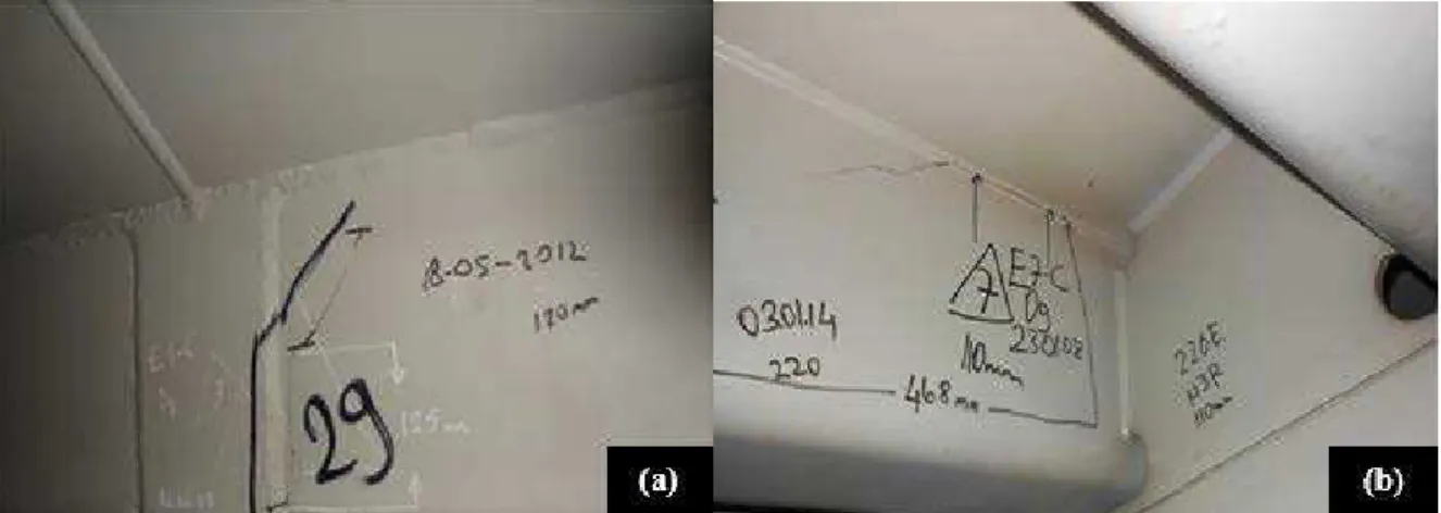
Furthermore, as illustrated in Figure 1, several fatigue cracks were found in the Fatih Sultan Mehmet Bridge in Istanbul, Turkey, the main goal of this research coming out of this finding. Fatigue cracks have been discovered and identified, and have gradually increased in OSDs, generally originating from and occur due to repeated out-of-plane bending owing to repeated wheel loads. These fatigue cracks generally initiate at welded joints that exist between connection plate and trough rib and subsequently propagate to the rib wall. Such fatigue damage may cause a sudden decrease in the longitudinal rib stiffness. Out-of-plane bending results in high local flexural stresses in the welded joints between the connection plate and trough rib, because the plate and trough rib thicknesses are relatively small.
Figure 1: Fatigue cracks in trapezoidal longitudinal rib: (a) initiated at the welded joint, and (b) propagating to the rib wall.
The topic of fatigue resistance of OSDs, ever since the phenomenon of fatigue resistance first appeared in bridges(de Freitas, Kolstein and Bijlaard, 2011; Ju and Tateishi, 2014; Liu, Wang and Liu, 2015), has been deeply and rigorously investigated. In OSDs, the most widely-used rib-to-deck welded connections are also most fatigue- sensitive locations due to direct wheel loading, and many researchers have focused on this topic.
Sim, Uang and Sikorsky (2009) studied how weld melt-through process and measures taken to control distortion affected the fatigue resistance of the rib-to-deck plate welded joints, through the use of six orthotropic deck specimens that were full-sized. They determined that, where the weld roots were fully penetrated, no crack could be identified, while pre cambering appeared to be an advantage for fatigue resistance.
(Sim and Uang, 2012), in their ongoing work, continued in their effective notch stress approach to carry out finite-element analyses of the test specimens. The results demonstrated that an increase in deck plate thickness helped in the reduction of stresses. However, there was little to no effect when reducing rib wall thickness.
(Xiao et al. 2008), using finite element (FE) software, performed local stress analyses and fatigue evaluation of rib-to-deck joints in OSDs while wheel loads were being applied. It was shown that the surface stress in the deck plate far exceeded the stress in the rib wall which had a weld penetration of 75% into the wall of the rib.
Ya, Yamada and Ishikawa (2011) showed that when fatigue tests were performed on rib-to-deck specimens for fatigue, particularly on specimens with partial joint penetration (PJP) and weld melt-through (WMT) together, as well as 80% PJP and WMT separately, the WMT specimens seemed to show a smaller amount of reduction of fatigue strengths than the 80% PJP specimens. However, this discrepancy may have been due to a normal scattering of test data such that there were comparable fatigue strengths in both details.
Liu et al. (2014) created refined FE models by taking a multi-sub-model approach in order to analyze the structural hotspot stresses in rib-deck welded joints. Also, the researchers explored the effects of the radius of the weld toe, the mesh size, and the weld profile.
affect stress endemic to rib-to-diaphragm welded joins, and more advanced geometry inspired by an FE parametric study was proposed.
By employing a full-scale laboratory test, (Connor and Fisher, 2006) put forward a procedure to determine the values of the stresses found in rib-to-diaphragm connections, which is consistent with the fatigue resistance provided by the bridge design specifications of AASHTO (2012).
In addition to the efficacy of repairing cracks using stop-holes in an orthotropic steel bridge, (Choi and Kim, 2008) determined the stress properties and behavior of the fatigue crack of longitudinal rib-to-crossbeam joints.(Oh et al. 2011), in their analytical and experimental research, proposed optimal height, thickness, and cross-beam shear area parameters as well as the efficiency and shapes of bulkhead plates with the aim of countering fatigue cracks. Xiao et al. (2006) studied the reasons of fatigue cracks that had been identified in longitudinal ribs of the Kinuura Bridge in Japan. The researchers determined as a result of their experimentally and theoretically study that a lack of penetration zones, low fatigue strength of the butt-welded joints would occur.
Yokozeki and Miki (2016) carried out experimental and analytical work to determine the fatigue performance of connections between longitudinal U-ribs and transverse ribs both containing and not containing a slit on the transverse rib web. Fatigue test results for the slit connections evaluated by SHSS show agreement with previous fatigue data of similar connection details. No fatigue crack was initiated on the connection without the slit after 4.6 million cycles compared to fatigue failure of the slit connection at 0.7 million cycles.
Liu et al. (2016) established the fatigue crack propagation numerical simulation method for U-rib butt weld of orthotropic steel bridge deck based on the theory of probabilistic fracture mechanics. The results show that by the established numerical simulation method, a relatively accurate crack propagation process can be simulated, which provides a theoretical tool for its fatigue life estimation.
Cheng et al. (2017) investigated experimentally the fatigue tests of rib-to-deck welded connections in orthotropic steel bridge decks by obtaining structural hot spot stresses at weld toes. Research includes fatigue cracking process with S-N curves. They also proposed a simplified formulae of crack growth rate to estimate the fatigue resistance of such rib-to-deck welded connections composed of 16 mm thick deck plates and 80% PJP welds.
(Kainuma et al. 2017), in their experimental study, investigated the fatigue behaviors of rib-to-deck welded joints in orthotropic steel decks for different structural parameter. The results demonstrated that fatigue cracks did not occur where the stresses were purely compressive and increasing the penetration rate had the beneficial effect of preventing root cracking. Increasing the deck plate thickness from 12 mm to 16 mm showed a significant improvement in the fatigue durability. Finally, they came up with some important conclusions in welded joints such as grinding the weld toe could avoid crack at toe but might lead to a deeper root crack, and the press straighten could be an effective treatment for preventing root cracks which are propagating in depth.
Wei and Jiang (2017) carried out fatigue life evaluations using finite element method (FEM) in order to explore the fatigue performance of U-shaped rib-to-deck welded joints of orthotropic steel bridge decks under cyclic loading, based on linear elastic fracture mechanics (LEFM). Results show that fatigue life calculated with LEFM is greater than the value in Eurocode 3, and fatigue life of the welded joint will be considerably longer when the deck plate thickness is 16-18 mm and initial crack length is less than 0.1 mm.
Zhang, Liu, et al. (2017) based on finite element numerical analysis, explained the fatigue performance improvements of composite bridge deck with large longitudinal rib which is under the effect of typical fatigue prone stress range. The results indicate that the stress levels of rib-to-deck plate joints and longitudinal-to-diaphragm welding joints can be significantly reduced with composite bridge decks. Also the opening of diaphragm is an important structural detail for the control of the fatigue performance of steel bridge deck.
Zhang, Zhang, et al. (2017) utilized a new type of steel and ultra-high performance concrete (UHPC) orthotropic composite bridge deck with the large longitudinal U ribs to understand the improvement on the mechanical behavior over the traditional orthotropic steel bridge deck. The results indicate that the composite bridge deck has good applicability to the continuous girder bridges of medium spans and the fatigue behavior of the composite bridge deck is significantly superior to the traditional one. Also the increase of the opening width of the U ribs can cause an increase in the stress levels of the welded joints connecting the U ribs and the top plates.
the bulkhead shape affects the stress levels of the weld toe of the rib-to-floor beam connection weld significantly.
(Fu et al. 2018), studied the fatigue performance of a roof-U rib weld on orthotropic steel bridge decks by fatigue experiments on 40 specimens. They considered the influences of amplitude, penetration rate, loading position, and steel strength. The study shows that the increase of penetration rate can decrease the crack propagation rate and extend failure fatigue life. A larger steel strength can increase the fatigue strength with respect to crack initiation. They also concluded that under the same loading conditions, the fatigue life up to crack initiation is about half of the ultimate failure life.
Ming Li; Yasuo Suzuki; Kunitaro Hashimoto; and Kunitomo Sugiura (2018) studied the fatigue tests resistance of rib-to-deck joint in orthotropic steel bridge deck for two groups of RD joint specimens with weld-penetration ratios of 15 and 75% to assess the influence of the weld-penetration ratio on the fatigue-crack type and its fatigue resistance. Fatigue-test results suggest that the fatigue resistance of the RD joint specimens with 75 and 15% penetration ratios were approximately Class B and between Class C and Class D, respectively, per Japanese standards. Furthermore, results show that increasing the weld-penetration ratio can prevent root-to-throat fatigue cracks and enhance the fatigue resistance of RD joints.
Cui et al. (2018) presented a strain energy-based method to evaluate the service life of welded joints in the OSD considering the combined effects of stochastic traffic load on the deck-to-rib welded joints and associated residual weld stresses. The results show that there is a better coincidence between the predicted fatigue life using the presented approach and the inspected fatigue life in contrast with the conventional approach of neglecting the effects of residual stresses
Yang, Kainuma and Jeong (2018) investigated the effect of rib fractures on the structural response by carrying out the field tests at an actual bridge with artificial cracks by gas-cut and the results showed that once the fatigue cracks occurred at butt weld of ribs, the longitudinal stress is carried by the stiffener would be transferred to the localized deck plate and adjacent ribs.
From the literature it is understood that investigations of the characteristic fatigue life, propagation of fatigue cracking, and the mechanics of the failure under cyclic loading are severely limited for (RR) butt-welded connections. This study aims to address these issues experimentally for trapezoidal longitudinal ribs on orthotropic bridge decks in a controlled fashion for (RR) butt-welded connections. A static finite element model was carried out in order to assess the validity of the experimental setup. At the beginning of the tests, strain values under static loading were compared and checked with the numerical results for each specimen. Experiments were performed on six trapezoidal rib specimens, including five specimens with initial cracks which were created at the transverse butt-welded connections located at the bottom of the existing ribs. Last specimen was considered as a control specimen. A centric load was considered as the simulation of tire loading on the deck. Crack propagation characteristics were observed for the cracked specimens and S-N diagrams for each case were produced which are potentially useful for the evaluation of fatigue life of cracked members. Based on the results, conclusions regarding the fatigue life and failure mechanism of cracked (RR) butt-welded connections were drawn.
2 EXPERIMENTAL SET UP WITH NUMERICAL VERIFICATION
2.1 Details of Longitudinal Ribs
Figure 2: Trapezoidal longitudinal rib details (dimensions in mm).
According to the drawing in Figure 2, in the experiment, six full-scale (RR) butt-welded connections were manufactured. Each specimen is formed with a deck plate, two trapezoidal ribs, and a connecting rib as details were given. The legs of the ribs were welded to the deck plate using PJP, while complete joint penetration (CJP) was applied at the RR connection edges. This was carried out using carbon dioxide gas arc welding, in strict accordance with the American National Standard Welding Code (2011). The details of a typical specimen are illustrated in Figure 3.
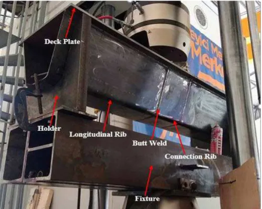
Figure 3: Experimental specimen details.
2.2 Test Rig
2.3 Set up Verification
2.3.1 Strain Gage Measurements
Five strain gages were attached to the control specimen from the rib bottom side in the longitudinal direction in order to measure the strains near the (RR) butt-welded connections, as illustrated in Figure 4. The first step (considered to be the most important step in strain gage installation) was surface preparation, which was necessary to produce a chemically clean surface with appropriate roughness, alkalinity, and layout lines. The surface preparation was performed in accordance with the Vishay (2009) Micro-Measurements Application Note B-129-8. A static load was successively applied to the specimen. While the static test was being performed, specimens were loaded within the elastic range and the monotonic load was gradually raised to its maximum value in several equal-sized load increments/steps. A load of 100,000 N was applied at the center of the specimen and strain values were obtained at each gage locations.
Figure 4: Gage installation in field.
2.3.2 Material Properties and FE Modeling of Ribs
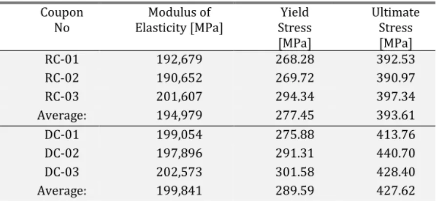
All of the plates used to manufacture the specimens were S235 steel material. Following static calibration and dynamic fatigue tests, tensile testing coupons were cut from the web (rib steel plates) and flange (deck steel plates) of specimen 2. The rib coupons (RC1 through RC3) had a 6 mm test thickness, while the deck coupons (DC1 through DC3) had a 12 mm test thickness, and the tests performed in accordance with ASTM E8/E8M (2009). The measured material properties are shown in Table 1, which indicates the modulus of elasticity (E), yield stress (Fy), and ultimate stress (Fu). The test was conducted using an Instron machine, as illustrated in Figure 5.
Table 1: Tensile Coupon Test Results.
Coupon No
Modulus of Elasticity [MPa]
Yield Stress [MPa]
Ultimate Stress [MPa]
RC-01 192,679 268.28 392.53
RC-02 190,652 269.72 390.97
RC-03 201,607 294.34 397.34
Average: 194,979 277.45 393.61
DC-01 199,054 275.88 413.76
DC-02 197,896 291.31 440.70
DC-03 202,573 301.58 428.40
Average: 199,841 289.59 427.62
Figure 5: (a) Coupons while testing, and (b) coupons geometry following test.
In order to verify the experimental set up before commencing to execute cyclic test, the rig was modeled via the finite element analysis program ABAQUS (Simulia, 2018). The longitudinal ribs, deck plate welds, and connection rib were defined using S235 steel material with the elastic-plastic material model (metal plasticity). The Young’s modulus is taken as 195 GPa and 200 GPa for ribs and deck plates respectively. A Poisson’s ratio of 0.3 is used for whole model. A bilinear curve is used for fit of the elasto-plastic material model to the experimental yield stress and ultimate stress. The average values for the yield and ultimate stresses are used from Table 1. The load is applied with a rigid cylindrical rod since loading apparatus of the machine is assumed to relatively rigid with respect to the other structural members. All of the materials in the FE model were defined using a solid homogeneous material type. The boundary conditions of the longitudinal rib and deck plate at each end location were constrained with respect to rigid body displacements but are allowed to rotate freely.
The connections between the longitudinal rib and deck plate were modeled using a tie constraint in the analysis. Also the interaction among the connection rib, weld, and longitudinal rib were selected as tie constraint to provide the full connection. Hard contact interaction and friction were defined between the loading rod and the deck plate. The holders and the support assembly are assumed to be rigid and only the holder parts are modeled with discrete rigid elements as can be seen in Figure 6.
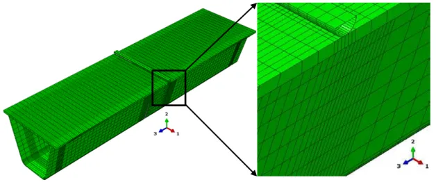
Metal plasticity is used in the analysis despite the load level was not over the elastic range. Thus yielding and other nonlinear effects were of no interest (Håkansson, 2015). Except for the target connections which include the connections rib, welds and a small part of the longitudinal ribs in the middle of the model, the mesh size for the entire model was approximately 25 mm. The mesh size in connection regions were selected at 5 mm. Eight-node linear brick element (C3D8R) defined for the whole mesh element type, as illustrated in Figure 7. An axial load of 100,000 N of concentrated force was applied to the center of the deck plate. This is considered the maximum load of one wheel when a truck is fully loaded with a dynamic amplification factor.
Figure 7: Finite element assembly mesh with target connections.
2.3.3 Numerical Results and Discussion
Figure 8: Vertical deflection (U2 - mm), Longitudinal strain (LE33 - mm/mm), Maximum principal stress (MPa) contours.
The main point of the numerical approach in this study was to determine the strain values in the same strain gage positions that were fixed on the specimen in the experimental static loading test so that set up can be verified. The three different longitudinal paths that were examined numerically are illustrated in Figure 9. These paths were taken along the bottom of the model, which considered the most critical locations and would be exposed to the greatest deformations. Path 1 passed through Strain Gages 1 and 3, Path 2 passed through Strain Gage 2, and Path 3 passed through Strain Gages 4 and 5. The details for these gages are displayed in Table 2.
Table 2: Strain Gage Locations in the Model.
Gage No Approximate Position
Gage 1 5 mm from weld joints
Gage 2 300 mm from weld joints
Gage 3 Center of model 750 mm from beginning of model edge Gage 4 Center of model 750 mm from beginning of model edge
Figure 9: Location of strain gages.
As can be seen from Figure 10 strain data correlates well with the numerical model and all assumptions made for rigid parts can be considered realistic. This also shows that the holder fixture does not have any effects on the experiment. Thus cyclic test indeed will reveal true fatigue characteristics of the RR butt connection.
Figure 10: Comparison of strain gage values of numerical and experimental approaches along longitudinal paths.
1 3
4 5
2
path 1
path 2
3 EXPERIMENTAL FATIQUE INVESTIGATION
3.1 Fatigue Data Measurement
Following completion of the static calibration load tests, all data were analyzed, and it was decided to conduct dynamic fatigue with test parameters. The experimental fatigue loading formed a sinusoidal shape with only a compression part. Cyclic fatigue loads were applied for all specimens, so that the minimum load was one tenth of the maximum
(
R
=
P
min/
P
max=
0.1
)
and the maximum applied load was 100,000 N. Cyclic loading was appliedusing a sinusoidal function with a constant frequency of 2 Hz and load control. As soon as the specified criteria for failure of vertical rigidity were achieved, the fatigue tests were terminated. The specimens were tested using these parameters until failure occurred. Crack length measurements were made by eye and recorded approximately at every 5,000 cycles for each specimen, and the test was run continuously. The important aspect of the fatigue analysis was to determine the extent to which the crack grew under each cycle of applied loading and counting the number of cycles that would lead to failure that could be carried out (Liao, 2011).
3.2 Observations of Fatigue Failure
3.2.1 Identification of Crack Propagation Phases
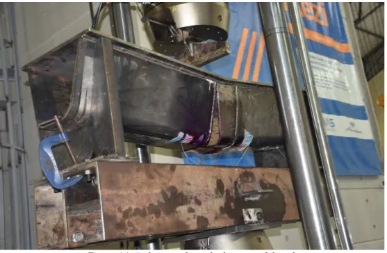
Fatigue cracks at the (RR) butt-welded connections were mainly caused by out-of-plane bending, which is the mode I loading. The failure modes of the five trapezoidal rib specimens with initial cracks were similar, represented by an opening mode at the bottom of the ribs and indicated by local displacements that are symmetric with respect to the x-y and x-z planes, and the two fracture surfaces were displaced perpendicular to one another in opposite directions (Barsom and Rolfe, 1999). Figure 11 illustrates the typical failure modes of the five specimens with initial cracks, where fatigue cracks were all observed on the butt-welded connections, generally near to the center of the rib arc.
Figure 11: Failure mode at the bottom of the rib.
The beginning of the crack and the process of its growth will occur in three phases:
Because the study focused on the areas around the initial crack tips, these were manually adjusted according to the crack growth during the entire test process, by using either the dye-penetrant or dynamic stiffness crack detection method, both of which were implemented in this study. The crack initiation locations are consistent with the highest stress concentration that were identified from the static calibration test and computer simulations.
Figure 12: Initial crack at transverse butt-welded connections.
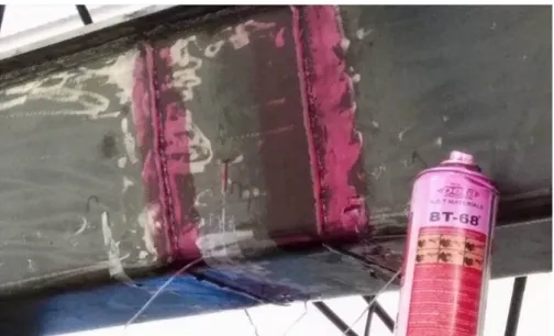
Phase II: As the cyclic loading continued, the crack steadily propagated away from its two tips, up to the outer tip proximal to the terminating point of the rib wall, and finally reached the rib edge. The paths of the crack growth at all times continued along the toes of the butt weld on the rib. Relative to other states, the rate of the crack growth during this phase was low, and the inner tip propagated faster than the outer tip because of the direct effect of cyclic loading. During this propagation phase, as their opening widths gradually enlarged, the cracks had become increasingly visible to the naked eye when using dye-penetrant crack detection, as illustrated in Figure 13. The test was monitored and the specimen was inspected for possible fatigue cracking at regular intervals. In the dye penetrant method, the procedure recommendations were firstly achieved by spraying BT68 spray onto the specimen on the parts where cracks were expected to occur, the function of which is to penetrate inside the cracks rapidly. Repeated spraying BT69 served to clean only the surface part that was sprayed with BT68, following which it was wiped dry with a cotton cloth. The use of these two sprays made the cracks visible to the naked eye, and the method was applied without stopping the test. This phase concluded upon the onset of cracks appearing on the top surface of the butt-welded connections, and the displacements of the maximal crack openings on the butt-welded connection of the rib bottom surface were found to be up to 1mm.
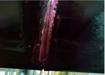
Phase III: The outer tip of the crack had to propagate along the thickness of the butt weld, and finally ran through it. The crack depth measured at this location increased rapidly as the cyclic loading was repeated, and the inner tip of the crack continued to extend forward at a high speed. The outer tip of the crack, which ran through the thickness of the weld, was extended in the vertical direction perpendicular to the loading axis (towards the inner tip) step by step and increasing crack parts ran through the weld. Consequently, parallel to the weld joints, a visible longitudinal crack formed on the wall and bottom surface of the rib plate, and the measured opening widths were up to 5 mm, as seen in Figure 14.
Figure 14: Extended fatigue crack thickness along butt-welded connections.
Furthermore, the inner tip of the crack continued its propagation along its initial path to the un-cracked edge of the rib plate. The rate of the growth of the crack during this phase was noticeably higher than previous instances, as the tips of the crack were less constrained than previously. This final phase finished upon the specimen having completely cracked and all the connections failed owing to tearing of the rib plates.
3.2.2 Fatigue Crack Growth with Dye-Penetrant Method
Figure 15: Crack length versus number of cycles (R = 0.1).
Figure 16: Dynamic stiffness versus cycles for cracked specimens
Table 3: Propagation Crack Length versus Number of Cycles to Failure.
No. of Specimen No. of Cycles
to Failure
Propagation Crack Length to Failure
[mm]
Specimen 1 284,555 420
Specimen 2 217,260 360
Specimen 3 63,288 260
Specimen 4 209,529 330
Specimen 5 143,467 300
Control Specimen Runout No crack
Figure 17: Dynamic stiffness versus cycles for the control specimen
3.2.3 Determination of Crack Propagation with Dynamic Stiffness Data
The instantaneous or dynamic stiffness of the specimens was a parameter inferred from direct test measurements. Herein, the dynamic stiffness is defined as the change in the applied load divided by the change in deflection of the specimen for each recorded fatigue cycle, thus:
𝐾𝐾𝑑𝑑𝑑𝑑𝑑𝑑=∆𝑝𝑝/∆𝑑𝑑 (1)
A decrease in dynamic stiffness was demonstrated to be a direct indication of fatigue crack growth. The fatigue crack propagation could be predicted by recording and monitoring changes in the dynamic stiffness of a specimen throughout the fatigue test duration of a fatigue test. Moreover, Figure 16 presents the stiffness values versus every cycle during cycling load until fatigue. It was observed throughout the cycling load that the change in the stiffness value was small and almost a straight line, but the value suddenly changed downwards, which means that the specimens with initial cracks failed (Kaan et al. 2012). However, as seen in Figure 17, the stiffness line for the control specimen still does not exhibit any slope change, indicating that no noticeable cracks appeared during the test.
3.2.4 Fatigue Life
As failure was predicted to occur at the weld connections, all specimens were tested at a nominal stress range of 60.772 MPa, taken at the center of the butt-welded connections from the rib bottom side with 100,000 N of applied loading. Where the stress range was too small, the maximum stress state was taken from the actual state and not selected as being higher. Each of the specimens with initial cracks exhibited markedly shorter fatigue lives than the control specimen that was tested within the same stress range. Figure 18 presents this effect and shows how it indicates the number of cycles accumulated for each specimen in the form of an S–N diagram with the AASHTO (2007) fatigue design curves. The S–N curve is a relation between the stress range under constant amplitude loading and the number of cycles until fracture (Alemdar et al. 2012). Specimens with initial cracks underperformed the AASHTO Category E' fatigue curve by a significant margin, which may be explained by the lowest fatigue strength quality of the welds alone at the bottom of the ribs.
4 Conclusions Experimental Work
The conclusions below were established based on experimental tests.
The principal stresses on the bottom side of the trapezoidal rib, particularly at the connecting region, were higher than in other parts of the structural component; thus, fatigue cracks appeared from the bottom of the ribs.
The maximum deformations on the trapezoidal rib cross-section occurred closer to the bottom side of the rib. This demonstrates that the rib wall exhibits out-of-plane bending through the transverse directions. Following the crack appearance, they easily propagate as a result of out-of-plane bending.
All specimens with initial cracks developed fatigue cracks at the center of the transverse butt-welded connections where the initial crack developed. In these specimens, the cracks propagated at either the center or one end of the initial transverse weld toe and extended into the web in an orthogonal direction to the longitudinal axis of the specimens. Once a crack had propagated in these specimens, the crack growth rate increased exponentially, until yielding of the reduced web section resulted in failure.
During fatigue testing, it was concluded that the most effective method of detecting the onset of fatigue crack propagation was the modified dye-penetrant method. Another less effective method that was employed to detect the onset of fatigue crack propagation was the dynamic stiffness method.
By comparing the lives of fatigue specimens, it was concluded that specimens tested at the center of the transverse butt-welded connections from the bottom side of the trapezoidal rib provided an effective means of predicting the fatigue life. The fatigue life of specimens with initial cracks tested at a nominal weld toe stress range of 60.772 MPa achieved a level at or below the AASHTO Category E' detail, while the control specimen exhibited behavior at or above the curve expected for the AASHTO Category E detail.
The numerical analysis and experimental test data exhibited very strong agreement. Furthermore, although the stress range was low, the fatigue cracks propagated easily.
One apparent difference between actual situations and the experimental results is that the fatigue cracks that propagated following the weld direction reached the deck plate, while in actual situations, fatigue cracks originating from the weld direction may be one-third of the weld height. The reason for this may be that in real situations, the rib continues, whereas in the experimental specimens, it is only 1500 mm in length.
Two methods of crack detection revealed quite similar characteristics in their own terms. For example crack size- number of cycles graph of Dye-Penetrant method in Figure 15 shows a sudden jump in crack growth rate around 105 cycles whereas crack stiffness-number of cycles graph of dynamic crack stiffness detection method in Figure 16 shows a sudden loss of stiffness at the same number of cycles (105).
ACKNOWLEDGEMENTS
All of the tests were performed using an Instron machine, which was provided by project number TR10/15/YNK/0034 from the Istanbul Development Agency under the project name “Sönümleyici Mesnet Test Merkezi.”
References
AASHTO (2012) ‘AASHTO LRFD Bridge Design Specifications, 6th Edition’, American Association of State Highway and Transportation Officials (AASHTO), Washington D.C.
AASHTO (2007) ‘AASHTO LRFD Bridge Design Specifications, 4th Edition’, American Association of State Highway and Transportation Officials (AASHTO), Washington D.C.
Alemdar, F. et al. (2012) ‘Use of CFRP Overlays to Strengthen Welded Connections under Fatigue Loading’, Journal of Bridge Engineering, 17(3). doi: 10.1061/(ASCE)BE.1943-5592.0000230.
American, A. and Standard, N. (2011) ‘Structural Welding Code — Steel’.
ASTM E8/E8M (2009) ‘Standard Test Methods for Tension Testing of Metallic Materials’, American Society for Testing and Materials, West Conshohocken, PA: 194.
Brownjohn, J., Dumanoglu, A. and Severn, R. (1992) ‘Seismic analysis of the Fatih Sultan Mehmet (second Bosporus) suspension bridge’, Earthquake Engineering & Structural Dynamics. doi: 10.1002/eqe.4290211005.
Cheng, B. et al. (2017) ‘Experimental study on fatigue failure of rib-to-deck welded connections in orthotropic steel bridge decks’, International Journal of Fatigue, 103, pp. 157–167. doi: 10.1016/j.ijfatigue.2017.05.021.
Choi, J. and Kim, D. (2008) ‘Stress Characteristics and Fatigue Crack Behaviour of the Longitudinal Rib-to-Cross Beam Joints in an Orthotropic Steel Deck’, Advances in Structural Engineering, 11(2), pp. 189–198. doi: 10.1260/136943308784466224.
Connor, R. (2004) ‘Influence of Cutout Geometry on Stresses at Welded Rib-to-Diaphragm Connections in Steel Orthotropic Bridge Decks’, Transportation Research Record: Journal of the Transportation Research Board, 1892, pp. 78–87. doi: 10.3141/1892-09.
Connor, R. J. and Fisher, J. W. (2006) ‘Consistent Approach to Calculating Stresses for Fatigue Design of Welded Rib-to-Web Connections in Steel Orthotropic Bridge Decks’, Journal of Bridge Engineering, 11(5), pp. 517–525. doi: 10.1061/(ASCE)1084-0702(2006)11:5(517).
Cui, C. et al. (2018) ‘Strain Energy-Based Fatigue Life Evaluation of Deck-to-Rib Welded Joints in OSD Considering Combined Effects of Stochastic Traffic Load and Welded Residual Stress’, Journal of Bridge Engineering, 23(2). doi: 10.1061/(ASCE)BE.1943-5592.0001181.
de Freitas, S. T., Kolstein, H. and Bijlaard, F. (2011) ‘Sandwich system for renovation of orthotropic steel bridge decks’, Journal of Sandwich Structures and Materials, 13(3), pp. 279–301. doi: 10.1177/1099636210386848.
Fu, Z. et al. (2017) ‘Fatigue evaluation of cable-stayed bridge steel deck based on predicted traffic flow growth’,
KSCE Journal of Civil Engineering, 21(4), pp. 1400–1409. doi: 10.1007/s12205-016-1033-0.
Fu, Z. et al. (2018) ‘Experimental study on the fatigue performance of roof and U-rib welds of orthotropic steel bridge decks’, KSCE Journal of Civil Engineering, 22(1), pp. 270–278. doi: 10.1007/s12205-017-1725-0.
Håkansson, J. and H. W. (2015) Finite Element Design of Orthotropic Steel Bridge Decks. Chalmers University of Technology. Master’s thesis.
Ju, X. and Tateishi, K. (2014) ‘Fatigue Crack Behavior at Rib-To-Deck Weld Bead in Orthotropic Steel Deck’,
Advances in Structural Engineering, 17(10), pp. 1459–1468. doi: 10.1260/1369-4332.17.10.1459.
Kaan, B. N. et al. (2012) ‘Fatigue Enhancement of Welded Details in Steel Bridges Using CFRP Overlay Elements’,
Journal of Composites for Construction, 16(2). doi: 10.1061/(ASCE)CC.1943-5614.0000249.
Kainuma, S. et al. (2017) ‘Experimental investigation for structural parameter effects on fatigue behavior of rib-to-deck welded joints in orthotropic steel rib-to-decks’, Engineering Failure Analysis, 79, pp. 520–537. doi: 10.1016/j.engfailanal.2017.04.028.
Liao, J. (2011) Fatigue Damage in the Orthotropic Steel Deck with respect to the Trough-to-Deck Plate Joint in between the Crossbeams. Delft University of Technology. Master’s thesis.
Liu, R. et al. (2014) ‘Hot spot stress analysis on rib-deck welded joint in orthotropic steel decks’, Journal of Constructional Steel Research, 97, pp. 1–9. doi: 10.1016/j.jcsr.2014.01.012.
Liu, Y.-M. et al. (2016) ‘Study on fatigue life of U-rib butt weld in orthotropic steel bridge deck of Hong Kong-Zhuhai-Macao Bridge’, Zhongguo Gonglu Xuebao/China Journal of Highway and Transport, 29(12), pp. 25–33.
Ming Li; Yasuo Suzuki; Kunitaro Hashimoto; and Kunitomo Sugiura (2018) ‘Experimental Study on Fatigue Resistance of Rib-to-Deck Joint in Orthotropic Steel Bridge Deck’, Journal of Bridge Engineering, 23(2). doi: 10.1016/j.ijfatigue.2017.05.021.
Oh, C. K. et al. (2011) ‘Analytical and experimental studies on optimal details of orthotropic steel decks for long span bridges’, International Journal of Steel Structures, 11(2), pp. 227–234. doi: 10.1007/s13296-011-2010-6.
Pfeil, M. S., Battista, R. C. and Mergulhão, A. J. R. (2005) ‘Stress concentration in steel bridge orthotropic decks’,
Journal of Constructional Steel Research, 61(8), pp. 1172–1184. doi: 10.1016/j.jcsr.2005.02.006.
Sim, H.-B. and Uang, C.-M. (2012) ‘Stress Analyses and Parametric Study on Full-Scale Fatigue Tests of Rib-to-Deck Welded Joints in Steel Orthotropic Decks’, Journal of Bridge Engineering, 17(5), pp. 765–773. doi: 10.1061/(ASCE)BE.1943-5592.0000307.
Sim, H.-B., Uang, C.-M. and Sikorsky, C. (2009) ‘Effects of Fabrication Procedures on Fatigue Resistance of Welded Joints in Steel Orthotropic Decks’, Journal of Bridge Engineering, 14(5), pp. 366–373. doi: 10.1061/(ASCE)1084-0702(2009)14:5(366).
Simulia. (2018). ABAQUS FEA Version 6.14-5. Providence, RI. http://www.simulia.com.
Vishay (2009) ‘Surface preparation for strain gauge bonding’.
Wei, X. and Jiang, S. (2017) ‘Fatigue Life Prediction on Rib-to-Deck Welded Joints of Steel Bridge Deck Based on LEFM’, Xinan Jiaotong Daxue Xuebao/Journal of Southwest Jiaotong University, 52(1), pp. 16–22. doi: 10.3969/j.issn.0258-2724.2017.01.003.
Xiao, Z. G. et al. (2006) ‘Fatigue cracks in longitudinal ribs of steel orthotropic deck’, International Journal of Fatigue, 28(4), pp. 409–416. doi: 10.1016/j.ijfatigue.2005.07.017.
Xiao, Z. G. et al. (2008) ‘Stress analyses and fatigue evaluation of rib-to-deck joints in steel orthotropic decks’,
International Journal of Fatigue, 30(8), pp. 1387–1397. doi: 10.1016/j.ijfatigue.2007.10.008.
Ya, S., Yamada, K. and Ishikawa, T. (2011) ‘Fatigue Evaluation of Rib-to-Deck Welded Joints of Orthotropic Steel Bridge Deck’, Journal of Bridge Engineering, 16(4), pp. 492–499. doi: 10.1061/(ASCE)BE.1943-5592.0000181.
Yang, M., Kainuma, S. and Jeong, Y. S. (2018) ‘Structural behavior of orthotropic steel decks with artificial cracks in longitudinal ribs’, Journal of Constructional Steel Research, 141, pp. 132–144. doi: 10.1016/j.jcsr.2017.11.007.
Yokozeki, K. and Miki, C. (2016) ‘Fatigue evaluation for longitudinal-to-transverse rib connection of orthotropic steel deck by using structural hot spot stress’, Welding in the World, 60(1), pp. 83–92. doi: 10.1007/s40194-015-0272-x.
Zhang, Q.-H. et al. (2017) ‘Study of Mechanical Behavior of New Type of Orthotropic Composite Bridge Deck with Large Longitudinal U Ribs’, Bridge Construction.
Zhang, Q.-H. et al. (2017) ‘Study on Fatigue Performance of Orthotropic Composite Bridge Deck with Large Longitudinal Ribs’, Zhongguo Gonglu Xuebao/China Journal of Highway and Transport, 30(3), pp. 226–235.