Prototyping Small Robots for Junior
Competitions: MicroFactory Case study
D. Neves∗ M. Silva∗∗ J. Gon¸calves∗∗∗ P. Costa∗∗∗∗ ∗University of Porto, Portugal.
Email: [email protected]
∗∗Polytechnic Institute of Porto, Portugal.
Email: [email protected]
∗∗∗Polytechnic Institute of Bragan¸ca and INESC-TEC, Portugal.
Email: [email protected]
∗∗∗∗University of Porto and INESC-TEC, Portugal.
Email: [email protected]
Abstract:
In this paper it is discussed the proposal of a small robot prototype to be applied in the MicroFactory competition, a downsized version of the Robot@Factory competition. The MicroFactory is intended to help junior competitors to make the transition from the Junior Leagues to the senior competition Robot@Factory. The Robot@Factory competition takes place in an emulated factory plant, where Automatic Guided Vehicles (AGVs) must cooperate to perform tasks. To accomplish their goals the AGVs must deal with localization, navigation, scheduling and cooperation problems, that must be solved autonomously.
Keywords:
Mobile robot competitions, AGVs, Prototyping
1. INTRODUCTION
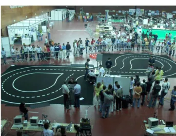
Robotic competitions are an excellent way to foster re-search and to attract students to technological areas (1). The robotic competitions present standard problems that can be used as a benchmark, in order to evaluate and to compare the performance of different approaches. Al-though there are many robotic competitions (2) (3) (4) (5), there is the need to create new ones, in order to solve new challenges. The factory environment is a prime candidate to use robots in a variety of tasks. A competition where mobile robots are tackling transportation problems in the shop floor is a challenge that can foster new ad-vances in service robots and manufacturing (6)(7)(8). The Robot@Factory is an official competition of the Robotics Portuguese Open, presenting problems that occur when using mobile robots to perform transportation tasks. The robots must be able to navigate, cooperate and to self-localize in an emulated factory plant, to transport and handle materials in an efficient way. The introduction of a downsized version of the Robot@Factory is intended to help junior competitors to make the transition from the Junior Leagues to the senior competition Robot@Factory. The downsized version of the Robot@Factory competition, the MicroFactory, reduces significantly costs for competi-tors and also for the organization, when compared with the standard competition. A picture of the 2006 edition of Robotics Portuguese open can be seen in Figure 1.
The paper is organized as follows: After a brief introduc-tion the Robot@Factory competiintroduc-tion is described, then a proposal of its downsized version is described, where it are discussed its benefits, when compared with the standard
Fig. 1. Robotics Portuguese Open
competition. Then it is detailed a proposal of a Micro-Factory robot prototype and finally some conclusions and future work are pointed out.
2. ROBOT@FACTORY COMPETITION
In this section it is presented the Robot@Factory compe-tition description and the rules that teams must follow in order to qualify for participation. This competition is an official competition of Robotica, the Main Robotics Por-tuguese Competition, since 2011. The official competition arena is shown in Figure 2.
Preprints of the 11th IFAC Symposium on Advances in Control Education, Bratislava, Slovakia, June 1-3, 2016
Fig. 2. Competition arena.
2.1 Robot dimensions
Each robot must fit within a cuboid of 45 x 40 x 35 cm. The robot must be completely autonomous and cannot establish any kind of communication with external systems that are not explicitly provided by the organization.
2.2 Competition arena
The competition arena, shown in Figure 2, emulates a fac-tory shop floor where there are warehouses and machinery. The dimensions of this area is 3.5 x 2.5 m. There are eight
machines available and two warehouses. One of them is used as a raw material storage and the other one is used as a destination.
2.3 Machinery and warehouses description
Each machine provides an area where the pieces should be placed in order to be processed by the machine. The robot must pick and place the part materials from the machine. While the part is placed in the machine it is processed and should not be removed. An RGB LED indicates that the machine is able to accept parts (light green), the machine is processing a part (yellow light), the part in this machine is already processed (white light) or that the machine is broken (blink red light).
2.4 The part materials
The materials to be transported by the robots should re-spect standard dimensions, width and length correspond-ing to an Europallete 80 x 120 mm (1:10 scale), the height should have a value between 30 mm and 50 mm. Each piece has an LED showing an RGB color that identifies the type of material. When a part arrives to a machine, it can be processed and its color is changed in order to illustrate a different type of part.
2.5 Solving problems in the competition
Team responsible can access the robot up to four times, if one of the robots is not expected to be able to recover. While robot comes out from the arena the time scheduling continues unchangeable.
2.6 Competition starting
The robots must be placed in the closed park one hour before the start of each competition. Teams should not to have access to the robot until about 10 minutes before the start of their competition. There, the referees indicate the teams that should prepare the robot to start their competition.
2.7 Competition rounds
Since this is a competition that can accept participants with different background, it must be differentiated in three rounds. Event organization can provide, for some rounds, an external localization system for robots. This system will identify the robots using a pattern that must be placed on top of each robot and can provide the position and orientation of the robot.
First round The main purpose of the first round is to collect the pieces of the raw material warehouse and transport them to the end warehouse. The robot should transport the most parts it can from the warehouses.
Second round The main purpose of the second round is to process some parts of the raw material. The raw material should be transported from the initial warehouse to the machinery, in order to be processed. When the processing task is ended, the parts should be transported to the final warehouse.
Third round The main purpose of the third round is to sequentially distribute the parts through several machinery. Some parts collected from the raw material warehouse should be placed sequentially in more than one machine to process. Only after the completion of this operation the parts should be transported to the final warehouse. There will be three types of parts in operation. During this round some tracks may be partially or totally blocked. In this round teams are authorized to use two robot at the same time, the used robots must cooperate to perform its tasks.
3. MICROFACTORY COMPETITION
The introduction of a downsized version of the stan-dard Robot@Factory competition is intended to help ju-nior competitors to make the transition from the Juju-nior Leagues to the senior competition Robot@Factory. The downsized version of the Robot@Factory competition, the MicroFactory, reduces significantly costs for the competi-tors and also for the organization, when compared with the standard competition. The main differences from the Robot@Factory competition, when compared to its down-size proposal, are essentially the following items:
• The dimensions reduce (both in the Arena as well as in robot).
• In order to reduce complexity, for the organizers and competitors, the machines and part materials do not have leds to provide the robots information about their status.
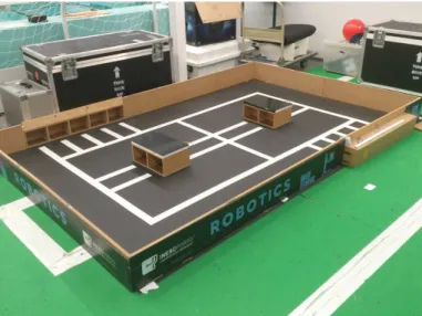
Fig. 3. Downsized robot arena with dimensions in mm
3.1 Competition Arena
The arena dimensions are shown in Figure 3, the lines on the floor can be used by the robot to navigate in the arena.
3.2 The part material
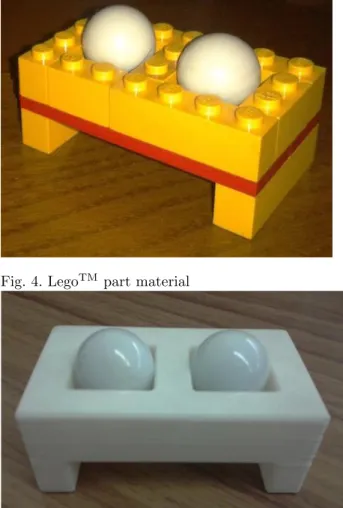
The part materials and the machines do not have informa-tion provided by leds, being the state of the part material identified by the number of marbles in the part material. Examples of part materials are shown in Figures 5 and 6, where two alternatives are shown, being possible the use of 3D print technology as well as the use of LegoTM
.
3.3 Machinery and warehouses description
The two, previously presented, prototyping alternatives (LegoTM
and 3D print) are also possible to be used in the development of machines, raw material and final destination warehouses. An example of the LegoTM
usage in a Machine prototyping is shown in Figure 6. The competition machine will be prototyped using 3D print technology, being provided with a system that drops marbles into the material parts when their status has to be changed.
4. MICROFACTORY ROBOT PROTOTYPE
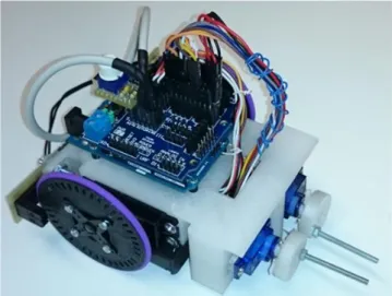
In the MicroFactory competition each team is free to prototype their own robot, as long as its fits within a cuboid of 20 x 20 x 20 cm, as alternative they can use an official robot provided by the organization. The official robot prototype was developed using an open source hardware and software arquitecture, being all its details provided to the teams by the organization. The prototyped mobile robot consists in small prototype, being presented in Figure 7, that uses inexpensive hardware, such as servo motors, an Arduino Uno platform, an infra-red detector array and For the sensor and actuator interface it was used an Arduino Servo and Sensor Shield. The robot was prototyped using 3D print technology, as an example the robot chassis 3D printer models is presented in Figure 8.
In the next subsections the prototype sensors and actua-tors are described.
Fig. 4. LegoTM
part material
Fig. 5. 3D printed part material
Fig. 6. Machine
4.1 Sensors
Zumo reflectance sensor The robot is equipped with the Zumo (9) reflectance sensor, providing an easy way to add line sensing or edge detection. It features six separate reflectance sensors, each consisting of an IR emitter coupled with a phototransistor that responds based on how much emitter light is reflected back to it. The purpose of using the referred sensor is to sense and follow a line. A Zumo reflectance sensor array is shown in Figure 9. More information about this sensor can be found in (9).
Fig. 7. Robot prototype.
Fig. 8. Robot prototype 3D Chassis printer model.
Fig. 9. Zumo reflectance sensor (9).
the cost of the robot prototype. It is based on IR emitters coupled with phototransistors, applied to obtain two sig-nals in quadrature. The robot with encoders is shown in Figure 10.
Fig. 10. Robot with encoders.
The use of incremental encoders it is only necessary to obtain the actuator model, prototypes with and without encoders are available. A compact wheel for the robot without encoders is shown in Figure 11 and a wheel prepared for the robot with encoders is shown in Figure 12.
Fig. 11. Robot compact wheel.
4.2 Actuators
Fig. 12. Robot wheel prepared for encoders use.
Locomotion actuator The robot locomotion actuator is the Futaba S3003 Servo. The Futaba S3003 servo motor has three inputs: PWM (white), power (red), and ground (black). Based on the PWM signal the servo will turn its shaft to a position within a range of approximately 200◦. When a PWM command is given to the circuitry an
error signal is produced. This error signal turns the motor in the appropriate direction. The motor gearing turns a position potentiometer, which gives a feedback signal to the position control circuitry. When the correct position is indicated by the potentiometer, the error signal becomes small enough, so the motor stops turning. For the proposed robot, continuous rotation is necessary, so the locomotions servo motors must be modified. This modification consists in disconnecting the position potentiometer from the gear train, setting the potentiometer for a known PWM signal and removing the angle stops from the motor shaft. Some offset developed by software is necessary to get the two motors to turn at the same speed. More detailed information of the Futaba S3003 servo motor and its modification can be found in (10). In order to obtain the actuator model it was necessary to know for each control signal the output velocity of each modified servo-motor, incremental encoders were used for that purpose, the actuator was powered with 6 Volt.
The control signal is the same as for a standard servo, only this time the length of the on time pulse will affect the speed and directions. For a certain pulse width the servo will stop. Values above or below will make the servo rotate faster in either direction. The signal (d), depicted
in Figure 13, is the difference for the stopping pulse width. This value must be divided by 40000, in order to obtain the time in seconds. As there is a gearbox with an high ratio, the dynamic response is very fast. The most important aspect of the model is the non linearity introduced by the modified controller. This non linearity can be seen in Figure 13 where the steady state speed for a certain pulse width has a small dead zone and a non linear behavior as it approaches the maximum speed. In order to model these non linearities, equation 1, saturated for values inferior to zero, was estimated. Using the experimental speed measures the best fit was found by optimizing the values
of a2..a0, b2..b0. The total error, being the sum of the absolute differences, was used as the target function (11). The estimated parameters can be seen in Table 1.
ω(d) =a2.d
2
+a1.d+a0
b2.d2+b1.d+b0
(1)
Parameters Value
a0 -34.760E-6
a1 -69.581E-3
a2 488.777E-3
b0 -29.663E-6
b1 2.278E-3
b2 -1.964
Table 1. Estimated parameters.
Fig. 13. Futaba S3003 Model.
In order to invert equation 1, equation 2 can be obtained. The solution for equation 2, corresponds to equation 3, resulting in a function with its domain from 0 to 5.955
Rad/s, that has as input a velocity and as output the servo control signal.
(ωb2−a2)d 2
+ (ωb1−a1)d+ωb0−a0= 0 (2)
d= −b±
√
b2 −4ac
2a (3)
where:
•a=ωb2−a2 •b=ωb1−a1 •c=ωb0−a0
For an input inside the referred function’s domain, equa-tion 3 returns two values, the chosen value must be equal or greater than 7 and less or equal than 293. Values from 0 to 6 are inside the dead zone and values superior to 293 correspond to the saturation zone.
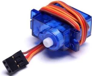
Fig. 14. T-Pro Mini Servo SG-90 9G.
5. CONCLUSIONS AND FUTURE WORK
The introduction of a downsized version of the Robot-@Factory is intended to help junior competitors to make the transition from the Junior Leagues to the senior com-petition Robot@Factory. The Robot@Factory comcom-petition takes place in an emulated factory plant, where Automatic Guided Vehicles (AGVs) must cooperate to perform tasks. To accomplish their goals the AGVs must deal with local-ization, navigation, scheduling and cooperation problems, that must be solved autonomously.
The downsized version of the Robot@Factory competition, the MicroFactory, reduces significantly costs for competi-tors and also for the organization, when compared with the standard competition. The introduction of passive ele-ments in the Robot competition arena reduces complexity in competition setup implementation. The fact that the teams that do not implement hardware have access to a robot prototype provided by the organization is very important to promote the competition to a wider audience.
The robot locomotion actuator is the Futaba S3003 Servo. For the proposed robot, continuous rotation is necessary, so the locomotion servo motors must be modified. This modification consists in disconnecting the position poten-tiometer from the gear train, setting the potenpoten-tiometer for a known PWM signal and removing the angle stops from the motor shaft. Some offset developed by software is necessary to get the two motors to turn at the same speed.
The presented sensor and actuator prototype description and accurate models provides the participating teams valuable knowledge, that can be very helpful in order to develop higher performance robot control software.
As future work the authors intend to provide the official competition robot prototype with a sensor that gives the robot information concerning the part status, identifying the number marbles in each part and also to evaluate the effectiveness of the introduction of the new robot competition.
ACKNOWLEDGEMENTS
This work is financed by the ERDF European Regional Development Fund through the Operational Programme for Competitiveness and Internationalisation - COMPETE 2020 Programme, and by National Funds through the FCT Funda¸c˜ao para a Ciˆencia e a Tecnologia (Portuguese Foundation for Science and Technology) within project POCI-01-0145-FEDER-006961.
REFERENCES
[1] Almeida, L., Azevedo, J., Cardeira, C., Costa, P., Fonseca,P., Lima, P., Ribeiro, F., and Santos, V., Fostering advances in research, development and ed-ucation in robotics.Proceedings of the 4th Portuguese conference in Automatic Control, 2000
[2] Browning, B., Bruce, J., Bowling, M., and Veloso, M., Ustp: Skills, tactics and plays for multi-robot control in adversarial environments.IEEE Journal of Control and Systems Engineering, 2005
[3] Lund, H. and Pagliarinis, L., Robocup jr. with lego mindstorms, International Conference on Robotics and Automation, San Francisco, CA, IEEE, 2000 [4] Nakanishi, R., Bruce, J., Murakami, K., Naruse, T.,
and Veloso, M., Cooperative 3-robot passing and shooting in the robocup small size league.Proceedings of the RoboCup Symposium, Bremen, Germany, 2006 [5] Ribeiro, F., Moutinho, I., Silva, P., Fraga, C., and Pereira, N., Controlling omni-directional wheels of a robocup msl autonomous mobile robot. In Scientific Meeting of the Portuguese Robotics Open, 2004 [6] Yuta, S., Asama, H., Thrun, S., Prassler, E., and
Tsubouchi, T., Field and Service Robotics, Recent Advances in research and Applications. volume 24 of Springer Tracts in Advanced Robotics, Lake Ya-manaka, Japan, 14-16 July 2003
[7] Arun N. Nambiar, Challenges in Sustainable Manu-facturing.Proceedings of the 2010 International Con-ference on Industrial Engineering and Operations Management, Dhaka, Bangladesh, January 9-10, 2010 [8] Gon¸calves, J., Lima, J.,Costa, P.,Moreira, A (June 2012). Manufacturing Education and Training resort-ing to a new mobile robot competition. Flexible Au-tomation Intelligent Manufacturing 2012 (Faim 12) Ferry Cruise Conference Helsinki-Stockholm-Helsinki
doi:10.1109/ICNN.1993.298623
[9] Pololu http://www.pololu.com/product/1419 2014
[10] Montana State University, Futaba
S3003 modification for continuous run-ning, http://www.coe.montana.edu/ee/-ecerover/servomod.html 2004
[11] Concei¸c˜ao, A., Moreira, A., Costa, P., Dynamic Pa-rameters Identification of an Omni-directional Mobile Robot, Proceedings of the International Conference on Informatics in Control Automation and Robotics, 2006.
[12] TowerPro SG90 Servo description and reviews