Experimental evaluation of coupler behavior for
mechanical rebar splices in reinforced concrete structures
Avaliação experimental de luvas para emendas
mecânicas de barras de aço em estruturas de
concreto armado
a University of Campinas, Civil Engineering Department, Campinas, SP, Brazil; b LENTON Company, São Paulo, SP, Brazil.
Received: 21 Dec 2017 • Accepted: 27 Jul 2018 • Available Online: 23 Nov 2018
V. G. CHIARI a, b
A. L. MORENO JUNIOR a
Abstract
Resumo
The use of mechanical splices to connect steel bars is an important solution in many infrastructure projects worldwide. In Brazil, this system is rarely used. The Brazilian standards regarding this subject are old and out of date; particularly with regard to the performance evaluation test methods for these splices in the laboratory. This paper presents and discusses the test procedure proposed in the international standard ISO
15835 [1] in light of the current procedure defined by Brazilian Standard ABNT NBR 8548 [2], applied to types of mechanical splices commonly
used in Brazil: taper threaded and bolted couplers. Performance parameters for these mechanical splicing systems related to structural integrity in reinforced concrete structures are evaluated on the basis of the results obtained in these tests. In the end, it is intended that this paper provide support for discussion of design procedures and laboratory performance evaluation of couplers for mechanical splices of steel bars in reinforced concrete structures in future reviews of Brazilian standard ABNT NBR 8548 [2].
Keywords: coupler, reinforced concrete, mechanical splice, rebar.
A utilização de emendas mecânicas para unir barras de aço é uma importante solução em muitas obras de infraestrutura no mundo todo. No Brasil este sistema ainda é pouco difundido. Além disso, a normalização Brasileira sobre o assunto é antiga, está defasada e carece de atualização; principalmente no que diz respeito aos métodos de ensaio para avaliação de desempenho destas emendas em laboratório. Este trabalho apresenta e discute o procedimento de ensaio proposto na norma internacional ISO 15835 [1] à luz do procedimento atual da norma Brasileira ABNT NBR 8548 [2], aplicado aos tipos de emendas mecânicas usualmente empregadas no Brasil: luvas rosqueadas tipo cônica e parafusadas. Parâmetros de desempenho destes sistemas mecânicos de emenda de barras de aço, relacionados à integridade estrutural em construções de concreto armado são avaliados com base nos resultados obtidos nestes ensaios. Pretende-se, assim, que este trabalho ofereça subsídios para discussão de procedimentos de avaliação de desempenho de luvas para emendas mecânicas de barras de aço em estruturas de concreto armado, nas futuras revisões da norma Brasileira ABNT NBR 8548 [2].
1. Introduction
The steel bar splicing region is always treated with special attention in guidelines, codes of practice, and norms that specify parameters for the dimensioning of structural elements in reinforced concrete. As an example, it must be ensured that these splices are implemented in a way that does not interfere with the originally planned behavior of the structural element in the region where they are located. Tensions in the structural element arising
from inefficient splices should be avoided, because of the risk of
the consequent undesired redistribution of force throughout the element and even the structure as a whole. It must therefore be assumed that the performance of a structural element, or even of a reinforced concrete structure, is directly related to the successful use of best practices in the event of splicing of its steel bars. Steel bars are generally spliced by lapping, by welding, or through mechanical systems using steel couplers. The lap splice is a
solution already consolidated in the world market, being the most
used system in reinforced concrete structures, mainly because it is the least expensive method. However, there are situations where this type of splice cannot be used, such as in the case of execution errors in the length of pillar starters, or “waits”, and especially in cases of structural restoration or reinforcement interventions, or even when it is desired to splice steel bars with diameters greater than the limit established for the lap splicing system. In such cases, designers may employ welded steel bars seams or steel couplers. In weld splicing, the steel bars are spliced by top-welding, by heating or electricity; or through copper-joints, with pressure-type autogenous solder being preferable. This type of splice has fallen into disuse in recent years, mainly due to the need for specialized labor and the time required for execution and strict quality control. Although it is, in many situations, the most expensive of the three
systems presented, the recognized effectiveness of the coupler
splicing system must be emphasized (Figure 1). According to Singhr et al. [3], the main advantages of using couplers for mechanical splicing are:
n Reduced steel frame congestion problems;
n Control of concrete crack propagation;
n Improvement in the structural continuity between bars, generating greater security;
n Reduction of labor and consequently the overall cost of the structure;
n Possibility of joining bars of any length and diameter.
Mechanical splices have been used in Brazil since the 1970s and
have been utilized in very significant projects in the Brazilian and
international scenario (the Angra I and II nuclear power plants and the Itaipu hydroelectric dam). However, the mechanical splicing of steel bars is still underused as a method when compared to the conventional lap splice.
Currently, it is possible to find a great variety of couplers in the Brazilian market. Among the most commonly used models are the
taper-threaded, shear bolted, cold-swaged, straight-threaded, and
steel-filled, whose technical characteristics are presented in Table 1.
There are few national publications currently evaluating couplers for the splicing of steel bars, which are mainly tested in isolation, i.e. without being inserted into a reinforced concrete structure. Even internationally, the subject is quite new and it is only in the
last 20 years that mechanical splices have been studied more frequently, due to the worldwide demand for this type of solution in major infrastructure projects.
Nouredine [4], Hillis & Saiidi [5], Rowell et al. [6], Alam et al. [7],
and Huaco & Jirsa [8] presented the first international results on
the performance of couplers as mechanical splice for steel bars. In a more complete study, Lloyd [9] evaluated the behavior of steel bars spliced with shear bolted couplers, 20 and 25 mm in diameter, under static and dynamic loads, according to the standard established by ASTM 1034 [10]. The results obtained proved the
efficiency of this type of splice.
The effectiveness of the instrumentation used to evaluate the
performance of these mechanical splices was approached in the research carried out by Alam et al. [7], Connah [11], Taskin [12],
Klimenov et al. [13], Ling et al. [14], and Seo et al. [15]. In this case, the proposed instrumentation had the objective of collecting deformation and/or displacement data, both on the part of the steel bar and splice coupler, in order to evaluate any possible relative slip between these two elements.
More recently, Haber et al. [16] evaluated the performance of two
types of steel coupler: taper-threaded and grout-filled (filled with a
cementitious mortar and applied only to precast structures) with a
diameter of 20 mm, according to the method specified in CALTRANS
670 [17], very similar to the method proposed by ISO 15835 [1].
The results of these tests proved the efficiency of the proposed
method, mainly with respect to the instrumentation used, where electrical extensometers were installed on the steel bars and on the couplers and displacement transducers were positioned on the bars to determine the relative displacement between bar and coupler. In the study by Nguyen & Mutusuyoshi [18], the performance of
grout-filled couplers in the mechanical splicing of steel bars was
evaluated. The test method was basically the same as that employed by Haber et al. [16] with subtle differences but proven effective
Figure 1
in its instrumentation. In this study, the displacement transducers
were not fixed to the bars, but to a hexagonal steel base specially made by the authors. Such instrumentation proved to be efficient in
evaluating the relative slip between steel bar and coupler.
Finally, it is important to highlight the importance of this type of splice in the connection of prefabricated concrete elements. This
type of linking has been studied in Brazil over the past 25 years, with some recent highlighted works being Ferreira [19], Ballarin
[20], Ferreira [21], Jeremias Junior [22], Souza [23], and Catoia
[24]. These studies are taken as references in the Brazilian
technical literature and supported the recently published revision of ABNT NBR 9062 [25]. With regard to international references, this type of study was conducted by Ordoñez et al. [26], Cheok and
Lew [27], Haber et al. [28] and Yu et al. [29].
When the various studies on the behavior of steel coupler mechanical splices in reinforced concrete structures are put into
context, a lack of national publications on the subject is noted,
both with regard to the individual performance evaluation of these mechanical splices and the evaluation of these splices together with reinforced concrete structural elements.
Therefore, the current article has the aim of presenting to the national technical environment a necessary performance evaluation of some types of mechanical splices utilized by the national construction industry, and also to present support for discussion of procedures (design and laboratory performance evaluation) in the future revision of ABNT NBR 8548 [2], when these procedures are compared to those established by international standard ISO 15835 [1].
2. Mechanical splice
performance parameters
It is assumed in the design that the potential presence of a mechanical splice between two reinforcing bars will not result in a
reduction of the structural strength, or of the stiffness or ductility of
the spliced bar. The current set of standards for concrete structure projects is based on this principle, specifying details of the
configuration of these splices that are more linked to how the steel and concrete work together than to guaranteeing the adequate
structural behavior of the mechanical splice in question. Hence the importance of guaranteeing the performance of these splices,
linked to the evaluation of specific parameters of interest through
standardized laboratory tests.
The performance evaluation of the mechanical steel splicing system in Brazil should follow the standard established by ABNT NBR 8548 [2], which, it is important to mention, requires revision
to insert parameters and performance-specific test methodologies
for the various types of couplers currently in use in the national construction industry.
Internationally, the ISO 15835 [1] standard is much more
complete than its national equivalent, however it is still lacking in
improvements in the model instrumentation standard for obtaining desired performance parameters. In this sense, it is important to note the adaptation to this instrumentation standard proposed by Haber et al. [16] and Nguyen & Mutusuyoshi [18].
Two performance parameters are essential in evaluating
Table 1
Mechanical splice couplers available on the brazilian market
Mechanical splice coupler Advantages Disadvantages
Taper-threaded
• Similar cost to lap splice • Easy to execute
• Uniform distribution of stress along the entire connected section • Excellent productivity • Self-alignment
• Quality control through use of torque wrench • Special equipment for carving threads
• Necessary to prepare the ends of the steel bars
• Not possible to carve threads on bars already installed
• Positioning sleeve necessary to use on deformed bars
Shear bolted
• Steel bar ends do not require preparation • Can be used for emergencies when bar is already installed
• Quick and easy installation • Excellent productivity
• Visual quality control (bolt will shear when it reaches the specified torque)
• High cost
• Difficult to splice deformed bars
Cold-swaged
• Does not require preparation of the steel bar ends
• Can be used on already-installed bars • Similar cost to lap splice
• Swaging press very heavy and difficult to install in tall buildings
• Difficult inspection and quality control • Low productivity
Straight-threaded
• Similar cost to lap splice • Good productivity
• Special equipment for carving threads
• Necessary to prepare the ends of the steel bars
• Not possible to carve threads on bars already installed
• Visual quality control
• Difficult to properly align bars during installation
Steel-filled
• Does not require preparation of the steel bar ends
• Low cost
• Difficult to install • Low productivity
mechanical steel bar splices: tensile strength (yield stress, fy, and maximum tensile stress, fst) and the relative slip between bar and coupler. Similar to Brazilian standard ABNT NBR 8548 [2], ISO 15835 [1] refers to the necessary similar behavior in terms of yield stress for both spliced and seamless bars.
In Brazil, the minimum required value for the yield stress of a bar connected by mechanical splicing is that prescribed by ABNT NBR 8548 [2], which establishes that the results obtained in the tensile stress tests on steel bars, with or without the couplers, must meet
the minimum requirements defined by ABNT NBR 7480 [30], that
is, for CA 50 type bars, fy must be 500 MPa, while fst should be 540 MPa (1.08 fy). Table 2 presents the main international standards for these same parameters and their respective minimum values for steels of similar classes [31] [32] [33] [34] [35].
Although not specified in the scope of ABNT NBR 8548 [2] and rarely taken into consideration for construction projects in Brazil
(other than nuclear power plants), the relative slip between bar and coupler is equally important to the structural evaluation, since it serves to measure the displacement tendency of the steel bar in relation to the coupler under extreme load conditions and, consequently, the reliability of the structural continuity.
International standard ISO 15835 [1], used as the main reference for this study, recommends a maximum slip limit of 0.1 mm. This
limit is also set out in the internal specifications of Eletrobrás Eletronuclear, known as DS-G-6647-029202 [36], which was
created and has been used in addition to ABNT NBR 11561 [37], which became obsolete in 2002. The slip limit value is also related
to the control of concrete cracking in the region around the splice.
3. Experimental program
The premise of the experimental program of this study was to
evaluate the procedures proposed in ISO 15835 [1] in the light of the national procedures of ABNT NBR 8548 [2], with instrumentation adapted according to Haber et al. [16] and Nguyen & Mutusuyoshi [18], for the mechanical splicing of steel bars with taper-threaded and shear bolted couplers.
The characterization tests of the unspliced steel bars, here called “control bars”, were carried out in the Laboratory of Construction Materials and Concrete at the Military Engineering Institute (IME) in Rio de Janeiro.
The second part of the experimental program, and the main focus of this study, was composed of tensile stress and slip tests on these same mechanically spliced bars, and was carried out in the Structures and Materials Laboratory at the State University of Campinas (UNICAMP).
In light of the objective of this study to comprehensively analyze
and compare the behavior of splice couplers with different tests
and instrumentation (test method) described in the national and
international literature, three different test methods were used to evaluate the spliced bars. Table 3 details the three different methods used (ABNT NBR 8548 [2], ISO 15835 [1] and
DS-G-6647-029202 [36]), the number of loading cycles to obtain slip (1 or 3 cycles) and the arrangement of the transducers to obtain the relative slip between bar and splice (suggested by Haber et al. [16] and Nguyen & Mutusuyoshi [18]).
The two types of mechanical splices to be evaluated were chosen because of their recent use in Brazil and because they
are currently the types most specified in structural designs as a
solution for the mechanical splicing of steel reinforcement bars in concrete structures worldwide. The diameters of the spliced bars, 20 mm and 25 mm, were also chosen because they are commonly used and of a size where the size of lap splices becomes so large the mechanical splicing with couplers becomes a more promising
Table 2
International standard f
yand f
stvalues for steel grade identical to CA 50
Country Standard Steel grade Yield stress fy (MPa) Maximum tensile stress fst
Germany DIN 1045 [31] 500M 500 550 (1.10 fy)
Austria ONORM B4700 [32] 550 550 620 (1.13 fy)
France NF-A-32-020 [33] 500 500 550 (1.10 fy)
Netherlands BRL-0504 [34] 500 500 550 (1.10 fy)
United Kingdom BS 8110 Appendix
TA1-B [35]
B500A B500B B500C
500
525 (1.05 fy) 540 (1.08 fy) 575 (1.10 fy)
Table 3
Test procedures applied to mechanically spliced bars
Method 1 Method 2 Method 3
Stress resistance ABNT NBR 8548 [2] ISO 15835 [1] ISO 15835 [1]
Slip
Adaptation of DS-G-6647-029202 [36] with the application of a single load
cycle
ISO 15835 [1] with the application of three load
cycles
ISO 15835 [1] with the application of three load cycles
Instrumentation
Adaptation of Haber et al.
[16], electrical extensometers and individual transducers
Adaptation of Haber et al.
[16], electrical extensometers and individual transducers
Adaptation of Nguyen & Mutusuyoshi [18], electrical extensometers and transducers
option, according to the consensus in the national technical environment.
3.1 Materials
The materials used in this study were as follows:
n CA 50 type steel bars, with diameters of 20 and 25 mm;
n Shear bolted couplers1 (Figure 2 [38]): composed of torquimetric bolts that allow the full force of the steel bar to be used and improve the structural integrity in both traction and compression;
n Taper-threaded coupler2 (Figure 3 [39]): manufactured with tapered thread at both ends.
3.2 Sample dimensions
In order to verify the physical and mechanical properties of the steel bars used in this study, the requirements described in the national standard ABNT NBR 6152 [40], ABNT NBR 7480 [30], and ISO 15630 [41] were followed, including those dealing with sample size.
The national ABNT standard NBR 8548 [2] specifies that steel bars
should be separated into three distinct segments (l1 and 2l) as shown in Figure 4, and the mechanical performance of isolated bar of length l1, whose minimum length should be 1000 mm should be evaluated, along with that of the spliced bar of length 2l. It should be noted that the lengths of the indicated bar segments depend solely on the diameter of the steel bar (d) to be evaluated, and thus are independent of the type of splice employed.
In a similar manner, the size of the spliced bar samples, as recommended by ISO 15835 [1] (Figure 5) should be calculated as a function of the diameter of the bar, d, to be spliced. However, the length of the coupler (L1) used should be considered when calculating this segment.
3.3 Characterization tests of seamless steel bars
(control bars)
Whether for the control bars (bars without mechanical splices) or for the bars with splice couplers, representative sampling for each
1 This system is being used more and more frequently in Brazil, especially in emergency situations, where conventional couplers cannot be used, because there is no need for any type of
preparation of the steel bar ends (threads). Its installation is performed with an impact wrench and the bolt head shear occurs when the specified torque is reached, allowing for visual quality
control.
2 This connection system is the one most used around the world due to its ease of alignment with the steel bar during installation. This splice is carried out using specially developed equipment. For proper quality control, the use of a torque wrench is indispensable.
Figure 2
Taper-threaded coupler [38]
Figure 3
Shear bolted coupler [39]
Figure 4
Sample for mechanical splice qualification
test, modified from ABNT NBR 8548 [2]
Figure 5
type of coupler, diameter, and test method must be composed of three samples, according to Brazilian standard ABNT NBR 7480 [30] and international standard ISO 15630 [41].
Following the methodology proposed by ABNT NBR 6152 [40], six bars of CA 50 type steel, three being 20 mm in diameter and another three being 25 mm, were tested in an isolated manner in order to characterize them with regard to tension and compression, in addition to verifying if they met the minimum values for yield stress (fy) and maximum tensile stress (fst) imposed by ABNT NBR 7480 [30]. To perform these tests, a universal test machine with a capacity
of 1000 kN and automatic load control was used: Automatic
Progressive Loading.
The tensile stress tests were based on Brazilian standard ABNT NBR 6152 [40]. The instrumentation of the control bars was set up by installing two electric strain gauges exactly at the center of the bars, on opposite sides, in order to measure the deformation of the steel bar at this central point throughout the test. Both extensometers were connected to a Vishay model P3 portable data acquisition unit. Figure 6 shows the steel bar after having ruptured, with detail of the installed electrical extensometers.
3.4 Principal tests: behavior of mechanically
spliced bars to tension
Three tests were performed for each diameter, coupler type, and
instrumentation method, making a total of 36 tests, whose purpose
was to measure the tensile strength and slip of the samples with mechanical splices. Although Brazilian standard ABNT NBR 8548 [2] does not specify the slip parameter in its scope, it was measured in all trials.
The tests of the bars spliced with couplers were carried out in a
universal testing machine with capacity of 1000 kN and automatic
loading control. Figure 7 illustrates the dimensions of the sample
Figure 6
Detail of control bar rupture after tensile stress test
Figure 7
spliced bars, according to ISO 15835 [1], which considers the length of the type of coupler used in the splicing.
As suggested by Haber et al. [16] and Nguyen & Mutusuyoshi [18], four electrical extensometers were installed on each spliced bar, two of them on the steel bar (Figure 8A) at a distance of 2d from the outer edge of the coupler and two in the center of the mechanical splice itself (Figure 8B) in order to measure the deformation of the steel bar and compare it to the deformation of the coupler itself during the test.
As additional measuring instruments to measure the relative slip between bar and coupler, displacement transducers were
also positioned in each test. Figure 9 and Figure 10 illustrate the instrumentation applied to Methods 1 and 2, where the transducers were arranged individually and connected directly to the steel bar and the mechanical splice. Figure 11 and Figure 12 show the transducers mounted in groups of three, coupled to an apparatus specially developed for this study (Method 3). Figure 13 shows details of this apparatus.
In order to measure the relative slip parameter between bar and
splice, the recommendations of ISO 15835 [1], adapted by
DS-G-6647-029202 [36], were adopted in this study, which establishes the maximum slip limit to be 0.1 mm. This parameter was measured at
Figure 8
Detail of electrical extensometers: A - steel bar and B - coupler
Figure 9
Instrumentation scheme with individual
transducers used in test methods 1 and 2
Figure 10
the end of a load cycle (Method 1) or at the end of three load cycles (Methods 2 and 3) on the spliced bar (Figure 14). During each
cycle the sample was loaded to the specified service rated load for
the spliced steel bar (300 MPa in the case of the bars in this study) and then unloaded. After determining the relative slip parameter,
the samples were loaded until breaking in order to determine the
tensile strength parameters and consequent measurement.
Figure 11
Instrumentation scheme of transducers installed
in groups of three used in test method 3
Figure 12
Transducers in groups of three installed on the
fixed triangular steel bases used in test method 3
Figure 13
Three-dimensional detail showing the functions of
the apparatus used in test method 3
Figure 14
maximum tensile stress (fst) of the control bars, while Table 5 and Table 6 show the results for these same parameters from the bars mechanically spliced with couplers, in addition to the relative slip value between steel bar and coupler. All samples evaluated, with and without mechanical splicing, reached a yield stress of at least 500 MPa and a maximum tensile stress of at least 540 MPa, both values established by ABNT NBR 7480 [30].
BC -20mm - 1 555 659
BC-20mm - 2 555 655
BC-20mm - 3 540 671
BC-25mm - 1 545 638
BC-25mm - 2 542 663
BC-25mm - 3 550 716
Table 5
Results of performance tests on steel bars with taper-threaded mechanical splices
Test sample Method Yield stress fy
(MPa)
Maximum tensile stress fst (MPa)
Slip (mm)
RC-20mm-1
Method 1
528 641 0.10
RC-20mm-2 536 648 0.10
RC-20mm-3 535 641 0.02
RC-20mm-4
Method 2
541 646 0.11
RC-20mm-5 541 633 0.02
RC-20mm-6 535 630 0.12
RC-20mm-7
Method 3
541 635 0.03
RC-20mm-8 540 637 0.02
RC-20mm-9 533 637 0.00
RC-25mm-1
Method 1
565 702 0.03
RC-25mm-2 553 688 0.05
RC-25mm-3 570 693 0.01
RC-25mm-4
Method 2
566 682 0.03
RC-25mm-5 567 677 0.28
RC-25mm-6 556 675 0.10
RC-25mm-7
Method 3
565 681 0.02
RC-25mm-8 565 679 0.01
RC-25mm-9 565 674 0.03
Table 6
Results of performance tests on steel bars with shear bolted mechanical splices
Test sample Method Yield stress fy
(MPa)
Maximum tensile stress fst (MPa)
Slip (mm)
PAR-20mm-1
Method 1
532 621 0.02
PAR-20mm-2 535 649 0.07
PAR-20mm-3 532 657 0.01
PAR-20mm-4
Method 2
535 627 0.05
PAR-20mm-5 532 605 0.15
PAR-20mm-6 535 653 0.19
PAR-20mm-7
Method 3
533 654 0.01
PAR-20mm-8 538 641 0.05
PAR-20mm-9 616 710 0.02
PAR-25mm-1
Method 1
559 670 0.10
PAR-25mm-2 560 661 0.10
PAR-25mm-3 559 693 0.07
PAR-25mm-4
Method 2
558 667 0.14
PAR-25mm-5 564 640 0.30
PAR-25mm-6 564 704 0.05
PAR-25mm-7
Method 3
565 672 0.07
PAR-25mm-8 564 642 0.06
Figure 15 shows the typical evolution of specific deformations, as
a function of the tension, in the control bars used in this study. The behavior of the bars of both diameters can be seen to be
analogous up until the point of rupture, as foreseen and specified
by the manufacturer ArcelorMittal [42].
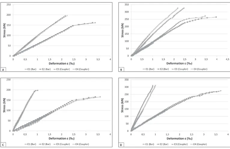
Figure 16 shows the evolution of specific deformations, as a
function of stress, in the spliced bars denominated RC-20mm (Figure 18A), RC-25mm (Figure 18B), PAR-20mm (Figure 18C), and PAR-25mm (Figure 18D), with “RC” corresponding to taper-threaded couplers and “PAR” shear bolted couplers, followed by the diameter of the steel bar tested (20 and 25 mm) and then by the number of the sample tested. Note that behavior is as expected for deformations in bars and couplers.
Regarding the maximum tensile stress, fst, determined in the tests, although it was found to be lower for the spliced bars when compared to the control bars in some tests, it should be emphasized that all the samples are in accordance with the requirements of ABNT NBR 7480 [30]; that is, for the CA 50 type steel bars used in this study, fy should be greater than 500 MPa, while fst should be greater than 540 MPa (1.08 fy).
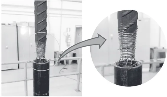
The ruptures of the spliced bars occurred almost entirely in the
region of the splice, without affecting, however, the integrity of
the couplers evaluated. In the case of the threaded couplers, the
bar was pulled out of the coupler after breaking the thread crests
through a combination of bending and shear stress. For the bolted couplers, the bolts ruptured through shearing. Figure 17 and
Figure 15
Stress-strain curves of the test control bars. A - BC-20mm; B - BC-25mm
Figure 16
Figure 18 illustrate, respectively, the typical mode of rupture observed for splices with threaded and bolted couplers.
For the slip parameter, based on the requirements established by international standard ISO 15835 [1], and in Eletrobrás
Eletronuclear’s internal document, DS-G-6647-029202 [36], 83%
of the samples had slip values below the maximum allowed limit of 0.1 mm. Samples that went above this limit were those based on Test Method 2, i.e. they used individual transducers to measure slip, performed at the end of three loading cycles.
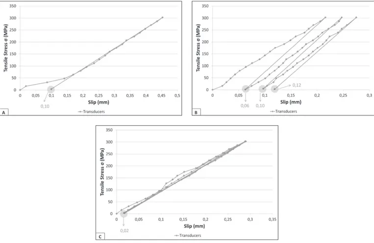
The number of load cycles before measuring the final slip value
and the installation of the transducers for measuring this slip are
shown in Figure 19. The final values, very different, clearly show
problems with the test methods being evaluated.
The bar evaluated by Test Method 1 (Figure 19A) showed 0.10 mm of slip at the end of a loading cycle. By Test Method 2, a similar bar
(Figure 19) showed slips of 0.05 mm at the end of the first loading
cycle, 0.10 mm at the end of the second cycle, and 0.15 mm at the end of the third loading cycle. Because the installation of the transducers, individually connected to the splicing bar, is the same for both methods, it can be concluded that this type of connection
Figure 17
Detailed view post-rupture of spliced bar with taper-threaded coupler
Figure 18
may be subject to possible transducer movements at the end of each load cycle; which, logically, could render both Method 1 and Method 2 unviable.
Figure 19C may be able to clarify some of the doubt expressed in the previous paragraph. Testing the same type of bar by Method 3, employing a special apparatus (Figure 13) for slip measurement, resulted in identical slip values (0.02 mm) at the end of each loading cycle for the spliced bar. This result would only be possible if there was no movement in the transducers at the end of each load cycle;
which demonstrates the efficiency of the proposed Test Method 3.
Regarding the number of load cycles, the consistency in the slip results at the end of each cycle illustrated in Figure 19C (0.02 mm) may
indicate that only one load cycle may be sufficient to obtain the final slip.
However, this fact should be explored more fully in future studies, where other types of mechanical splices and other diameters can be tested.
Although not specified in the instrumentation methodologies
evaluated in this study, the insertion of the electric extensometers in the center of the splice coupler was very useful for measuring the deformation of the material and to verify if there was any
influence on the slip parameter. In both cases, it has been noted
that the splicing coupler does not deform during the course of the test and, consequently, this deformation value can be neglected in the evaluation of the test results.
However, because it is a question of performance testing of the splice and the coupler is an important part of the system, the instrumentation may indicate behavior not suitable for the element during the test and, therefore, should be maintained in any possible proposal for performance evaluation of the mechanical splicing system of steel bars in reinforced concrete structures.
5. Conclusions
1. In accordance with the results of the experimental program developed in this study, it was found that mechanical splicing using taper-threaded and shear bolted couplers is an apt solution to provide continuity and structural integrity to reinforced concrete constructions, as its behavior complied with all pre-established norms and standards. It is important to
note that these findings are limited to the experiment performed
and the materials used in this research. The generalization of the conclusions is possible only with continuity of studies, obviously involving other types of steel couplers available in
Brazil (cold-swaged, straight-threaded, steel-filled, etc.).
2. Although it was not a parameter evaluated in this study, it is
of the utmost importance that the effective test length of the
sample being tested be based on the type of splice to be
Figure 19
evaluated, i.e. in the case of splicing with couplers, the length of the coupler and the diameter of the steel bar should be considered. Therefore, it is proposed that a procedure similar to ISO 15835 [1] be adopted and later implemented in the future revision of ABNT NBR 8548 [2].
3. The use of electric extensometers at various points on the sample was of great importance for recording its deformation and, consequently, for guaranteeing adequate mechanical behavior when evaluating the performance of the mechanical splicing system.
4. The test procedure referred to in this study as “Method 3”, with instrumentation based on Haber et al. [16] and Nguyen
& Mutusuyoshi [18], proved to be very efficient in obtaining the
parameters of interest: tensile stress and slip. With the addition of four electrical extensometers, two on the steel bars and two on the splice couplers, in addition to the group of three displacement transducers connected to a special apparatus, it was possible to monitor deformation and slip in minute detail throughout the test.
5. Regarding the number of load cycles, the consistency in the slip results obtained at the end of each of the three cycles by Test
Method 3 shows that only one load cycle may be sufficient to determine the final slip. However, this fact should be evaluated
further in future studies, where other types of mechanical splices and other diameters should be tested.
6. The ABNT NBR 8548 [2] standard is effectively out of date
and needs to be revised regarding the test procedures and parameters of interest to be obtained. It is therefore recommended to consider in its scope all methods and types of steel bar splice for reinforced concrete structures available in the national scenario, including in a future review, the slip parameter and its respective test method.
In conclusion, this article intends to contribute to the knowledge
of the requirements necessary for the development of new experimental studies involving mechanical splices, as well as
offering support for the discussion of performance evaluation
procedures and instrumentation for these splices in future revisions of the Brazilian ABNT standard NBR 8548 [2].
6. Acknowledgments
The authors would like to thank the LENTON company for supplying
the steel couplers and electric extensometers, as well as for their valuable technical information regarding the test methods applied.
They would also like to thank Arcelor Mittal for donating all of the steel bars and a special thanks to Prof. Dr. Luiz Antonio Carneiro
of the IME and the technicians of the Laboratory of Construction Materials and Concrete of the IME and the Laboratory of Structures and Materials at UNICAMP for their aid and assistance in carrying out the tests.
7. Bibliographic references
[1] INTERNATIONAL ORGANIZATION STANDARIZATION
(ISO). Steels for the reinforcement of concrete — Reinforcement couplers for mechanical splices of bars — Part
2: Test methods. ISO 15835-2. Geneva, Switzerland, 2009.
[2] ASSOCIAÇÃO BRASILEIRA DE NORMAS TÉCNICAS NBR 8548 – Barras de aço destinadas a armaduras de concreto armado com emenda mecânica ou por solda – Determinação da resistência à tração, Rio de Janeiro, 1984.
[3] SINGH R., Himanshu S. K., Bhalla N., Reinforcement
couplers as an alternative to lap splices: A case study. International Journal of Engineering Research & Technology, Vol 2 Issue 2, 2013, 6 p.
[4] NEUREDDINE, I. Plastic Energy Absorption Capacity of #18 Reinforcing Bar Splices under Monotonic Loading. MSc Thesis, California State University, Sacramento, USA, 1996, 108 pp. [5] HILLIS, D., and SAIIDI, M.S. Design, Construction, and
Nonlinear Dynamic. Analysis of Three Bridge Bents Used in a Bridge System Test,” Center for Civil Engineering
Earthquake Research, Department of Civil and Environmental
Engineering, University of Nevada, Reno, Nevada, Report No. CCEER-09-03, 2009, 82 pp.
[6] ROWELL, S.P., GREY, C.E., WOODSON, S.C., and HAGER,
K.P. High Strain-Rate. Testing of Mechanical Couplers,” US Army Corps of Engineers, Engineer Research and Development Center, Report No. ERDC TR-09-8, 2009, 74 pp.
[7] ALAM, M.S., YOUSEFF, M.A., and NEHDI, M.L.. “Exploratory Investigation on Mechanical Anchors for Connecting SMA Bars to Steel or FRP bars,” Materials and Structures, 2010, Vol. 43, pp. 91-107.
[8] HUACO, G. and JIRSA, J. Performance of Damaged Column Retrofitted with Innovative Materials and Devices,” 15th World Conference on Earthquake Engineering, 15WCEE, 2012, 10 pp. [9] LLOYD, W. R. Qualification of the Bar-Lock Rebar Coupler
for Use in Nuclear Safety-Related Applications Mechanical Testing Program and Performance Analysis,” Idaho National Engineering and Environmental Laboratory Materials Department, Report No. INEEL/EXT-02-01387, 2001, 22 pp.
[10] AMERICAN SOCIETY FOR TESTING AND MATERIALS
(ASTM). Standard Test Methods for Testing Mechanical Splices for Steel Reinforcing Bar. ASTM A1034A. Pennsylvania, USA, 2008.
[11] CONNAH, G. Prequalification of Mechanical Splices
for Reinforcing Bars in Seismic Conditions. Australian
Earthquake Engineering Society 2013 Conference,
Tasmania, Australia, 2013, 7p.
[12] TASKIN, H. Determining the Mechanical Properties of
Reinforcement Coupler Systems in Turkey. Special Edition Ejoir Magazine, Turkey. 2015, 10 p.
[13] KLIMENOV, V., OVCHINNIKOV, A. USTINOV, A., DANILSON, A. Stress-Strain State of Mechanical Rebar Couplings. Journal of Physics: Conference Series 671, 2016, 5 p.
[14] LING. J. H., RAHMAN, A. B. A., IBRAHIM, I. S., HAMID, Z.
A. Behavior of grouted pipe splice under incremental tensile load. Construction and Building Materials 33, 2012, 90-98 pp.
[15] SEO, S.Y., NAM, B.R., KIM, S.G. Tensile strength of the grout-filled head-splice-sleeve. Construction and Building
Materials 124, 2016, 155–166 pp.
[16] HABER, Z.B., Saiidi, M.S., Sanders, D.H. Behavior and simplified modeling of mechanical reinforcing bar splices.
[17] CT670 CALIFORNIA DEPARTMENT OF TRANSPORTATION (CALTRANS), Division of Engineering Services. Method of tests for mechanical and welded reinforcing steel splices. Sacramento, USA, 2011.
[18] NGUYEN, D. P., MUTSUYOSHI, H. Influence of Quality of
Mechanical Splices on Behavior of Reinforced Concrete Members. Research Report of Department of Civil and Environmental Engineering, Saitama Univ., Vol.41, 2015, 32-43 pp.
[19] FERREIRA, M. A. Estudo de deformabilidades de ligações para análise libnear em pórticos planos de elementos pré-moldados de concreto, São Carlos, 1993, Dissertação (mestrado) - Escola de Engenharia da Universidade de São Paulo, 183 p.
[20] BALLARIN, A.W. Desempenho das ligações de elementos estruturais pré-moldados de concreto, São Carlos, 1993, Tese (doutorado) - Escola de Engenharia da Universidade de São Paulo, 187 p.
[21] FERREIRA, M. A. Deformabilidade de ligações viga-pilar de concreto pré-moldado, São Carlos, 1999, Tese (doutorado) - Escola de Engenharia da Universidade de São Paulo, 253 p. [22] JEREMIAS JUNIOR, A. C. Análise da estabilidade de
estruturas pré-moldadas de concreto: influência das ligações
semi-rígidas, São Carlos, 2007, Dissertação (mestrado) - Universidade Federal de São Carlos, 218 p.
[23] SOUZA, A.S. Comportamento de elementos pré-moldados
de concreto com ligações semi-rígidas, São Carlos, 2006, Dissertação (mestrado) - Universidade Federal de São Carlos, 118 p.
[24] CATOIA, B. Comportamento de vigas protendidas pré-moldadas com ligações semi-rígidas, São Carlos, 2007, Dissertação (mestrado) - Universidade Federal de São Carlos, 215 p.
[25] ASSOCIAÇÃO BRASILEIRA DE NORMAS TÉCNICAS (ABNT). Projeto e execução de estruturas de concreto pré-moldado. ABNT NBR 9062. Rio de Janeiro, 2017.
[26] ORDOÑEZ, J.A.F. et al. Prefabrication teoría y prática. V.2.
Barcelona, Spain, 1974.
[27] CHEOK, G.S.; LEW, H.S. Performance of precast concrete
beam-t-column connections subject to cyclic loading. PCI Journal. V.36, n.3, 1991, 56-57 pp.
[28] HABER, Z.B.; SAIIDI, M.S.; SANDERS, D.H. Emulative
column footing connections for seismic designs in a accelerate bridge construction. 4th ECCOMAS Thematic Conference on Computational Methods in Structural
Dynamics and Earthquake Engineering, 2013, 8 p.
[29] YU, C.O.; ALRASYID H.; ZACHARY B. H.; HUNG J.L. Cyclic
Behavior of Precast High-Strength Reinforced Concrete Columns. ACI Structural Journal Novembro/Dezembro, 12 p., 2015, 839-850 pp.
[30] ASSOCIAÇÃO BRASILEIRA DE NORMAS TÉCNICAS NBR 7480 – Aço destinado a armaduras para estruturas de concreto armado - Especificação, Rio de Janeiro, 2007
[31] DEUTSHES INSTITUT FUR BAUTECHNIK DIN 1045 -
Tragwerke aus Beton, Stahlbeton und Spannbeton - Teil 1: Bemessung und Konstruktion, 2008, 15 p.
[32] AUSTRIAN STANDARDS INSTITUTE - ÖNORM B 4700
- Stahlbetontragwerke-EUROCODE-nahe Berechnung, Bemessung und konstruktive Durchbildung, 2000, 20 p.
[33] FRENCH STANDARD - NF A 35-020-2-1:2011, Steel products — Mechanical splices and mechanical anchorages for ribbed or indented reinforcing steel — Part 2-1: Test methods for mechanical splices, 2011, 11 p.
[34] NATIONALE BEOORDELINGSSRICHTLIJIN, BRL-0504 -
Mechanische verbindingen van betonstaal, 2000, 31 p. [35] BRITISH STANDARD – BS 8110 – Appendix TA1-B,
Requirements for mechanical splices, 2011, 16 p.
[36] ELETROBRÁS ELETRONUCLEAR - Documento n°
DS-G-6647-029202 [11], 2000, 25 p.
[37] ASSOCIAÇÃO BRASILEIRA DE NORMAS TÉCNICAS NBR
11561 – Qualificação, execução e controle em emendas
mecânicas de topo com luvas, destinadas a armações de concreto para centrais nucleoelétricas, Rio de Janeiro, 1990 [38] LENTON Taper Threaded Rebar Splicing Systems,
Cleveland, USA, 2011, 20 p.
[39] LENTON LOCK Especificação Técnica Cleveland, USA,
2011, 1 p.
[40] ASSOCIAÇÃO BRASILEIRA DE NORMAS TÉCNICAS NBR 6152 – Materiais metálicos – Ensaio de tração à temperatura ambiente, Rio de Janeiro, 2002.
[41] INTERNATIONAL ORGANIZATION STANDARIZATION
(ISO). Steel for the reinforcement and prestressing of concrete - Test methods - Part 1: Reinforcing bars, wire bar
and wire. ISO 15630-1. Geneva, Switzerland, 2009.