Conception of cable-stayed curved deck:
the effects of unilateral suspension
Concepção de tabuleiros curvos e estaiados:
os efeitos da suspensão unilateral
a University of São Paulo, Department of Structural and Foundation Engineering, Polytechnic School, São Paulo, SP, Brazil.
Received: 04 Aug 2017 • Accepted: 22 Feb 2018 • Available Online:
This is an open-access article distributed under the terms of the Creative Commons Attribution License
G. M. CHUNG a
F. R. STUCCHI a
Abstract
Resumo
In systems of suspended cable bridges, the cable-stayed bridges have been widely used because of its capacity to overcome large spans and
not require large areas of support during their execution, minimizing interference with existing vehicle flow or overcoming large spans in rivers and
channels that require space to the passage of vessels. In addition to this structural advantages, they are aesthetically well accepted by society, valuing the urban space and often making it a landmark.
This paper aims to describe the influence of unilateral suspension of decks on the behavior of cable-stayed bridges with curved decks through
structural models in order to evaluate whether structural gains or losses are relevant to project considerations. Results indicated that stresses
variation in the deck depends not only on the position of the cables and their forces (which depends on the stiffness of the deck), but also on the
cable itself and the central pylon.
Keywords: cable-stayed bridge, footbridge, curved deck, concrete.
Dos sistemas de pontes suspensas por cabos, as estaiadas têm sido largamente utilizadas devido à sua capacidade de vencer grandes vãos e
não demandarem grandes áreas de apoio durante sua execução, minimizando as interferências com o fluxo de veículos já existente ou vencendo
grandes vãos em rios e canais que necessitam de espaço para passagem de embarcações. Além dessas vantagens estruturais, são esteticamente bem aceitas pela sociedade, valorizando o espaço urbano e muitas vezes tornando-o ponto de referência.
Este trabalho visa descrever a influência da suspensão unilateral do tabuleiro no comportamento de pontes estaiadas curvas através de modelos estruturais aplicados a passarelas, a fim de avaliar se os ganhos ou perdas estruturais são relevantes para as considerações de projeto. Os resul -tados indicaram que a variação dos esforços no tabuleiro depende, além do posicionamento dos cabos e suas forças (que por sua vez dependem das rigidezes do tabuleiro), dos próprios cabos e do mastro central.
1. Introduction
The study of conception of cable-stayed bridges with curved decks is still not widespread in Brazil. With the improvement of techniques and Brazilians professionals, studies on these types of structural solutions have been increasingly deepened, lead-ing to the study and design of new solutions in order to optimize the available space and resources and minimize impacts on roadway structure.
The first cable-stayed bridge in Brazil began to be built in the year
2000. It is located in São Paulo and known as Santo Amaro Bridge-Station. It is noted that the use of cable-stayed bridges is still very recent in Brazil due to the fact that technology is not dominated at all levels involved, but mainly because the governors just started to understand that in some special cases it is preferable a higher investment in order to have a more attractive structure.
A highlighted cable-stayed bridge in Brazil is the Octávio Frias de Oliveira Bridge, which was inaugurated in 2008 in the city of São Paulo. The bridge, which is part of the Real Parque Road Complex, is composed of two independent curved decks that cross Pinhei-ros River and is the only cable-stayed bridge in the world with two curved decks connected to the same pylon (Berger [1]).
In situations where a straight way would not be sufficient to over -come an obstacle, curved bridges be-come necessary, and the knowledge of the techniques and theories underlying curved ca-ble-stayed bridges is a requirement for the study of a more
favor-able and/or optimized design, where all the factors influencing its
behavior must be evaluated, such as: curvature, pylon position, cables position and inclination and cross section geometry. Therefore, structural models were applied to footbridges that
al-low evaluating the influence of unilateral suspension of the deck.
When comparing models results with deck’s suspension by the in-ner side and the outer side of the curve, it is possible to evaluate the most favorable performance of the structure for each situation.
The parametric study of these effects and their understanding is
one of the most important purposes of this paper.
2. Methodology and formulation
2.1 Formulation and theories
Structures in general are well described by the Linear Theory of Elasticity, or simply Theory of Elasticity, in which two hypoth-eses are adopted and lead to the linearity of the formulated
problems: Geometric Linearity and Linear Elasticity. In the first, no distinction is made between the deflected and undeflected
shapes when formulating equilibrium equations. In the second, also known as Physical Linearity, it is assumed that stress and deformation components obey a linear relationship through the
elastic stiffness modulus.
The formulations of linear theory lead to satisfactory results in structures with small displacements. In the case of cable-stayed bridges, in which the elements are lighter and slenderer, such hy-potheses are no longer valid, which leads us to extend the analysis
to the Nonlinear Theory of Elasticity, where second-order effects are considered fundamental to stability analysis of more flexible
elements, as is the case of the stay cables that deform accord-ing to a catenary quite sensitive to the tensile force, and also of the central pylon, which is compressed by great axial force trans-mitted through the stay cables. The software chosen for analysis writes the equations of equilibrium in the deformed position taking
into account the effects of 2nd order in both cables and pylon, so
that Newton-Raphson’s method for the solution of non-linear equa-tions is used. Mathematically, the method is based on a gradual
increase (incremental) of the load. These effects also exist in the
deck which is quite compressed, but more rigid.
In curved beams, the calculation is more complex than in straight
beams due to the interaction between flexion and torsion, which
appear interconnected in the equilibrium equations. Moreover, when increasing the curvature, the torsion requests become con-siderable, which, on the other hand, determines an increase in distortion, i.e. deformation in the cross section, which generates transverse and longitudinal stresses that cannot be neglected.
For an infinitesimal curved beam element, according to Figure 1, the equilibrium equations are:
Equilibrium in y direction
(1)
Equilibrium in z direction
(2)
Equilibrium in x direction
(3)
2.2 Methodology
The main characteristic of cable-stayed bridges is the lightness of its structure, which results from the fact of having a series of inter-mediate supports represented by stay cables, which, despite their
greater deformability, are efficient.
For curved cable-stayed bridges, the cables, besides being po-sitioned to replace supports, should be so also to neutralize the
effects of curvature, which is possible by varying their position and
inclinations in the longitudinal and transverse planes.
In this paper, studies were performed for two configurations – inner
and outer suspension – with tri-dimensional models of bars and cables in SCIA Engineer1 software, in which Finite Element Method
Figure 1
IBRACON Structures and Materials Journal • 2018 • vol. 11 • nº 4
is used for non-linear analysis. The bars were used to represent deck and pylon, both of concrete, while the cables with fan
ar-rangement represent the steel stay cables, whose flexural stiff -ness are admitted null. This software presents a tool for cable elements so that it is possible to specify an axial force to be considered early in the processing as an initial tensioning on the element. In addition, due to the catenary that the cable presents
under the effect of its own weight, the cables would have to have
their modulus of elasticity corrected as proposed by the German engineer Franz Dischinger so that the cable could be modeled as a bar. However, this adjust was not necessary because the software already considers the initial geometry of the cable ele-ment as its catenary at the beginning of the processing. Therefore, in order to neutralize the structure initial deforma-tion due to its own weight and to obtain a good distribudeforma-tion of moments in the deck, an initial tensioning in the cables was ap-plied, whose determination is described in detail in Chung and Stucchi [3].
The physical properties of concrete and steel have complied with the recommendations of NBR 6118: 2014 [4].
As the unilateral suspension of the deck influences its behavior
and each cable anchors in a transverse girder, rigid bars were used to simulate the connection of the deck to the cables, since such connection does not occur in the center of gravity of the cross section.
In addition, it is known that torsional forces may occur due to fact that shear center does not coincide with center of gravity of the cross section. However, considering that in box sections these points are close, it is usual to consider the axis of the bar that represents the deck in the center of gravity, as it was done in this paper.
To evaluate the performance of the structure against curvature,
each configuration was compared to a secondary model, where the deck is made straight in order to neutralize the effects of
M/R portion of the equation (3).
Finally, the results were compared to a bilateral suspension model.
2.3 Strutural model
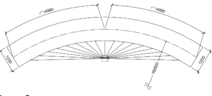
The study was developed for a footbridge with concrete com-pressive strength equal to 45 MPa, 50 cm thick box girder, 100 m length and 85 m radius, symmetrically suspended by stays spaced every 5 m, using 17 stay cables. Figure 2 and 3 illustrate the geometry.
The pylon was designed inclined, forming an angle of mately 80° with the horizontal. It has a total height of approxi-mately 40 m with all degrees of freedom restrained on the base, so that the deck is positioned on the pylon’s half height, and square cross-section of 5 m x 5 m.
The ends of deck are restrained to vertical and tangential dis-placements, conditioning the abutment with anchor block, and restrained to the torsional rotation, so that it simulates the con-nection with the pier cross beam.
Figure 4 to 6 present the isometric views of the structural mod-els with internal, external suspension and bilateral suspension, respectively.
Figure 2
Plan view of the deck: suspension by inner side
(units: cm)
Figure 3
Deck cross section (units: cm)
Figure 4
Model isometric view: suspension by inner side
Figure 5
According to the requirements of standard NBR 7188: 2013 [5], the live load on pedestrian footbridges is a uniformly distributed
load of intensity p = 5 kN/m², not increased by the impact coeffi -cient. The load is applied on section centroid, distant from 0.134 m of the middle axis of the deck, which causes a corresponding torsion of 8,04 kNm/m to be considered.
The internal torsion stresses in deck also result from the fact that the cross section centroid does not coincide with the shear cen-ter, generating torsion for both permanent and accidental loads. Table 1 summarizes the cables installed forces, in which L is the cable length and N the installed force.
3. Results and discussions
3.1 Shear and moments diagrams: suspension
by the inner side
Figure 7 to 14 present shear and moments diagrams of the curved deck suspended by the inner side, in which “P” indicates perma-nent load and “L” live load.
A sharp curve in moment diagram is shown in Figure 13. This is due to the transverse load on the pylon due to its own weight which, by being tilted, causes bending. By decomposing the dis-tributed load of the pylon’s own weight (W = 625 kN/m), inclined by 10° from the vertical, a transverse plot (T) of approximately
Figure 6
Model isometric view: bilateral suspension
Table 1
Cables installed forces
Cable Inner side suspension Outer side suspension Bilateral suspension
L (m) N (kN) L (m) N (kN) N int (kN) N ext (kN)
1 43,21 3278,47 49,20 2654,09 1924,57 2941,34
2 39,31 2656,05 45,23 3314,33 1047,82 2179,69
3 35,52 2940,19 41,46 2950,95 1020,03 2082,07
4 31,94 2792,90 37,96 2708,26 916,99 1905,44
5 28,65 2555,21 34,80 2486,64 822,79 1746,26
6 25,79 2314,96 32,12 2296,39 740,32 1609,97
7 23,53 2114,36 30,05 2148,46 674,67 1504,12
8 22,06 1981,00 28,74 2053,85 631,59 1436,46
9 21,54 1934,13 28,28 2021,19 616,47 1413,10
10 22,06 1981,00 28,74 2053,85 631,59 1436,46
11 23,53 2114,36 30,05 2148,46 674,67 1504,12
12 25,79 2314,96 32,12 2296,39 740,32 1609,97
13 28,65 2555,21 34,80 2486,64 822,79 1746,26
14 31,94 2792,90 37,96 2708,26 916,99 1905,44
15 35,52 2940,19 41,46 2950,95 1020,03 2082,07
16 39,31 2656,05 45,23 3314,33 1047,82 2179,69
17 43,21 3278,47 49,20 2654,09 1924,57 2941,34
Figure 7
IBRACON Structures and Materials Journal • 2018 • vol. 11 • nº 4 105 kNm/m (T = W x sin10° = 625 x 0,167 ≈ 105 kN/m). Assuming, for simplification, that the structural scheme of the pylon is close to a fixed-pinned supported beam, the expected positive moment
would be 9T.L² / 128, that is, 12220 kNm, a value close to the 13315 kNm obtained.
Figure 8
Bending moment on curved deck (P): internal case
Figure 9
Bending moment on curved deck (P+L): internal case
Figure 10
Torsional moment on curved deck (P): internal case
Figure 11
Torsional moment on curved deck (P+L): internal case
Figure 12
Shear force on curved deck (P+L): internal case
Figure 13
Bending moment on pylon (P): internal case
Figure 14
Table 2 summarizes the obtained results.
By developing the stress diagrams for the straight beam model (Figure 15), we have the results shown on Figure 16 and 17.
3.2 Shear and moments diagrams:
suspension by the outer side
Figure 18 to 25 present shear and moments diagrams of the curved deck suspended by the outer side.
Table 2
Moments and shear force summary
in curved deck: suspension by inner side
Forces Results
M DECK (kN m) 34087,4
T DECK (kN m) 130649,8
V DECK (kN) 1798
M PYLON (kN m) 20713,2
Figure 15
Model with straight deck: internal case
Figure 16
Bending moment on straight deck (P+L): internal case
Figure 17
Torsional moment on straight deck (P+L): internal case
Figure 18
Deformed configuration: external case
Figure 19
Bending moment on curved deck (P): external case
Figure 20
Bending moment on curved deck (P+L): external case
Figure 21
IBRACON Structures and Materials Journal • 2018 • vol. 11 • nº 4
Table 3 summarizes the obtained results.
By developing the stress diagrams for the straight beam model (Figure 26), we have the results shown on Figure 27 and 28.
3.3 Shear and moments diagrams:
bilateral suspension
Figure 29 to 36 present shear and moments diagrams of the curved deck suspended bilaterally.
Table 4 summarizes the obtained results.
3.4 Comparisons
A comparative summary of the unilateral systems is presented on Table 5.
When comparing the models with curved deck, it is verified that
when the cables are external the torsion moment is noticeably re-duced by the M/R portion given by equation ( 3 ) for approximately 20%. However, bending moments increase 2,5 times.
On the other hand, in the system with internal cables, comparing the curved deck with the straight deck, the torsion is increased by the unfa-vorable M/R portion and bending moments practically remain the same.
In straight deck configurations, it is observed that bending results obtained in the systems cases are different. This is because each
cable has been previously adjusted in order to neutralize deck’s ini-tial displacements, according to the procedure described in Chung
and Stucchi [3], and therefore tensioned with different values, pro
-viding different deck suspensions.
Besides, it was verified that the rigidity of the central pylon influences the ideal strength of cables for control of displace-ments, which in turn influence in their sustentation. To evalu-ate these effects, the same models were developed
consid-Figure 22
Torsional moment on curved deck (P+L): external case
Figure 23
Shear force on curved deck (P+L): external case
Figure 24
Bending moment on pylon (P): external case
Figure 25
Bending moment on pylon (P+L): external case
Table 3
Moments and shear force summary
in curved deck: suspension by outer side
Forces Results
M DECK (kN m) 86478,3
T DECK (kN m) 27568,6
V DECK (kN) 5076,6
Figure 26
Model with straight deck: external case
Figure 27
Bending moment on straight deck (P+L): external case
Figure 28
Torsional moment on straight deck (P+L): external case
Figure 29
Deformed configuration: bilateral case
Figure 30
Bending moment on curved deck (P): bilateral case
Figure 31
Bending moment on curved deck (P+L): bilateral case
Figure 32
Torsional moment on curved deck (P): bilateral case
Figure 33
IBRACON Structures and Materials Journal • 2018 • vol. 11 • nº 4
ering a reduction in pylon’s section from 5 x 5 m to 4 x 4 m, more flexible.
The results are shown on Table 6.
In this case, bending magnitudes in the deck are larger, as
expect-ed, so that to reduce these efforts would be necessary an increase
in cable tensioning, and possibly an increase in cables section in order to respect admissible tension.
Finally, the model with bilateral suspension indicated magnitude of solicitations in deck similar to the case of inner side suspension, in case of bending, and similar to the case of outer side suspension, in case of torsion.
3.4 Conclusions
The study reveals that in cases of unilateral suspension torsion can be reduced in curved decks when the cables are anchored by the outer side and not by the inner side as might be expected.
Figure 34
Shear force on curved deck (P+L): bilateral case
Figure 35
Bending moment on pylon (P): bilateral case
Figure 36
Bending moment on pylon (P+L): bilateral case
Table 4
Moments and shear force summary
in curved deck: bilateral suspension
Forces Results
M DECK (kN m) 36437,38
T DECK (kN m) 15434,76
V DECK (kN) 2316,35
M PYLON (kN m) 386494,05
Table 5
Comparison of results
Case MMAX (kN m) TMAX (kN m)
Curved deck
Internal susp. 34087,4 130649,8
Curved deck
External susp. 86478,3 27568,6
Straight deck
Internal susp. 37939 110830
Straight deck
External susp. 78461,8 51565,7
Table 6
Comparison of results: pylon with reduced stiffness
Case MMAX (kN m) TMAX (kN m)
Curved deck
Internal susp. 34478 130776
Curved deck
External susp. 98267 21679
Straight deck
Internal susp. 39788 100604
Straight deck
On the other hand, bending moments in the external suspension system are much higher when compared to the internal system. In addition, the general stress and forces in the structure are better
distributed in the internal configuration, especially considering py -lon solicitations. That is, the structure shows better overall perfor-mance when the cables are anchored on the inner side of the deck.
It should also be noted that in configuration with external cables,
the attendance to vertical clearance should be taken into account, as the cables pass over the board, which is why it is more common
to find curved footbridges suspended unilaterally from the inner side than from the outer side. The bilateral suspension configura
-tion, although efficient, presents the same clearance attendance
problem, besides not being as appealing as the internal
suspen-sion configuration.
4. References
[1] BERGER, D.; STUCCHI, F. R.; HERNANDO, C.; RIBEIRO, C. F. Executive control cable-stayed bridge Octávio Frias de Oliveira. In: Fédération Internacionale du Béton (FIB) Sym-posium, 11th, London, 2009, Proceedings of the annual
in-ternational fib symposium. London, 1986.
[2] BARBOSA, R. L. Pontes curvas unicelulares em regime elástico, São Paulo, 1997, Dissertação (mestrado) - Escola Politécnica, Universidade de São Paulo, 167 p.
[3] CHUNG, G.M.; STUCCHI, F. R. Concepção de tabuleiros curvos e estaiados. Revista Concreto & Construções, São Paulo, v.44, n.84, 2016, p.75-82.
[4] ASSOCIAÇÃO BRASILEIRA DE NORMAS TÉCNICAS. Projeto de estruturas de concreto - Procedimento. - NBR 6118, Rio de Janeiro, 2014.
[5] ASSOCIAÇÃO BRASILEIRA DE NORMAS TÉCNICAS. Carga móvel rodoviária e de pedestres em pontes, viadutos, passare-las e outras estruturas. - NBR 7188, Rio de Janeiro, 2013. [6] KEIL, A. Weit und krumm. Stahlbau, Berlin, v. 73, n. 12,
2004, p. 982-989
[7] STUCCHI, F. R. Sobre o comportamento estrutural das pon-tes celulares, São Paulo, 1982, Dissertação (mestrado) – Escola Politécnica, Universidade de São Paulo, 1v.