191
Abstract
The flow of proppant-laden fluid (PLF) in the fracture is a typical problem of solid-liquid two phase flow, and the transportation and deposition of proppants are es-sential to determine the flow conductivity of hydraulic fracturing. The self-suspending proppant with a water soluble surface coating is a newly presented supporting material and has great potential for hydraulic fracturing. The purpose of this paper is to under-stand the physical process, and investigate the effect of the self-suspending proppant on particle placement and transportation in the fracture. Two experiments of the PLF flow were conducted in a fracture, using the common ceramic proppant and self-suspending proppant, respectively. The fracture was formed by two parallel plexiglass planes, and was 4000 mm in length, 10 mm in width and 600 mm in height. It was found that four different zones developed when proppants were injected into the fracture continu-ously, which were the proppant bank zone, tumbling zone, suspending zone, and free zone. Compared with the common proppant, the self-suspending proppant changes the particle distribution in the fracture, and increases the thickness of proppant suspending and bank zone. The motion behavior of self-suspending proppants in the fracture is described. The conclusion is that appropriate reduction in the proppant concentration and density is beneficial to the good distribution and transportation of proppants in the fracture, and the self-suspending proppant favors the effective supporting of fracture.
keywords: two-phase flow; fracture; self-suspending; proppant; proppant-laden fluid. Peng Li
Doctorial candidate
Institute of Mechanics, Chinese Academy of Sciences - Key Laboratory of Mechanics for Fluid Solid Coupling System
School of Engineering, University of Chinese Academy Beijing - Beijing - China
Xuhui Zhang
Associate professor
Institute of Mechanics, Chinese Academy of Sciences - Key Laboratory of Mechanics for Fluid Solid Coupling System
School of Engineering, University of Chinese Academy Beijing - Beijing - China
Xiaobing Lu
Professor
Institute of Mechanics, Chinese Academy of Sciences - Key Laboratory of Mechanics for Fluid Solid Coupling System
School of Engineering, University of Chinese Academy Beijing - Beijing - China
Jianzheng Su
Professor
State Key Laboratory of Shale Oil and Gas Enrichment Mechanisms and Effective Development Beijing – Beijing - China
Zhiwen Huang
Associate professor
State Key Laboratory of Shale Oil and Gas Enrichment Mechanisms and Effective Development Beijing – Beijing - China
Xin Fan
Assistant professor
State Key Laboratory of Shale Oil and Gas Enrichment Mechanisms and Effective Development Beijing – Beijing - China
Experimental study on the
self-suspending proppant-laden
flow in a single fracture
Mechanic and Energy
Mecânica e Energia
1. Introduction
The PLF transportation and the deposition of the proppant determine the flow conductivity of the hydraulic fracture system, and the PLF flow is a typical fluid-solid two-phase flow problem (Woodworth and Miskimins, 2007). The geometrical characteristics of the fractures, the coupling physical effects of flow discontinuity, and variation of the fluid properties during the flow lead to the complexity that is of essence to researchers.
The main factors controlling the PLF flow are the diameter, density, proppant concentration, as well as the viscosity, veloc-ity, density of the fracturing fluid, together with the background pressure difference, and temperature (Eissa et al., 2007; Tsai
et al., 2012). Most of these parameters are varied according to the hydraulic fracture in practice, while the variation may lead to a flow transition. The transition from New-tonian fluid to non-NewNew-tonian fluid occurs with the increase of proppant concentration and fluid viscosity, while the transition of the laminar flow to the turbulent flow occurs with the increase of flow velocity (Eissa et al., 2007). These physical effects lead to great difficulties in the theoretical analysis and numerical simulations. Thus, experimental observation and measurement are essential to capture the basic data and physical characteristics.
In a single fracture, the fluid velocity affected the settlement of the proppant due to the shearing effect. At the bottom of the fracture, a zone with immovable proppant called proppant bank occurred. An equilibrium status with a balance bank
thickness and balance fluid velocity was reached when the whole PLF flow was stable and the proppant distribution in the fracture was unchanged (Kern et al., 1959; Babcock et al., 1967).
Settlement and convection are two main mechanisms of the PLF flow. The re-sistance coefficients of a single spherical and irregular shape solid grain in unbounded flow were obtained based on the Stokes equations (Stokes, 1850; Vanderhoef et al., 2005; Michaelides and Ebrary, 2006). The velocity of the PLF flow was heteroge-neously distributed in the fracture, which led to a difference in the proppant concen-tration. The convection flow occurred and was related to the width of the fracture, mainly while the settlement was affected by the diameter of the grain (Cleary and Fonseca, 1992; Abdulrahman, 1999). When the viscous force was less than the gravity, the convection effect was dominant (Clear, 1991).
Most of the study focused on the common PLF flow in the fracture. Dontsov and Peirce (2014), presented a model of PLF flow based on the assumption of Newto-nian fluid and spherical solid grains. The model could describe the transition of the Poiseuille flow to the Darcy flow due to the increase of the proppant concentration, and the distribution of flow velocity deviated from the parabolic shape. Shiozawa and McClure (2016) simulated the PLF flow based on the 3D hydraulic fracturing Model configuration software CFEAC, consider-ing the processes of proppant settlement, tip screen, and closing up of the fracture
(McClure and Home, 2013; McClure et al., 2016). The sensitivities of fluid viscosity, proppant density, and formation perme-ability were analyzed. The proppant settle-ment and PLF tip screen were harmful to the deposition and support of the fracture.
Common PLF is a mixture of ceramic proppant and jelly gel fracturing fluid with a velocity greater than water. The drawbacks of common PLF are high cost and serious damage to the reservoir. The self-suspend-ing proppant with water soluble surface coating is a newly presented supporting material for hydraulic fracturing, and is anticipated to benefit to the PLF transporta-tion and proppant depositransporta-tion because the volumetric density is less than that of the common proppant, and the dissolving of the surface coating increases the viscosity of the fluid. However, the understanding of the physical mechanism of the flow and particle deposition of the self-suspending proppant in the fracture is insufficient.
This paper aims to investigate the flow and particle deposition behavior of self-suspending in the fracture. Two comparative experiments, using common ceramic proppant and self-suspending proppant respectively, were conducted to investigate the evolution of the flow process of the PLF and the effect of self-suspending proppant on the flow and deposition. In Section 2, the experimental setup and procedures of the PLF flow in the fracture are introduced; in Section 3, the physical processes and results are il-lustrated, and the mechanism of the flow is preliminarily discussed.
2. Experimental setup and procedures
The apparatus system consisted of a mixing tank (100 L), two plexiglass planes, a pump and pipes. The two glass planes were fixed parallel to simulate a fracture with a width of 10 mm. The height and length of the testing section were 600 mm and 4000 mm, respectively (As in Figure 1). The mixing tank and the
fracture were connected through pipes with a diameter of 50 mm. The fluid with certain viscosity and proppant were placed into the mixing tank to obtain the homo-geneous PLF. The inlet of the fracture was in mesh structure (10 meshes with a height of 30 mm, equivalent interval distribution along the height of the fracture inlet). The
pump was used to propel the PLF to flow with a certain velocity and produce a circling flow. The flux was measured by an electromagnetic flowmeter, and the flow process was observed using a digital automatic zoom camera, including the development of the proppant settlement and PLF flow.
Figure 1
193 The fracturing fluids were water and
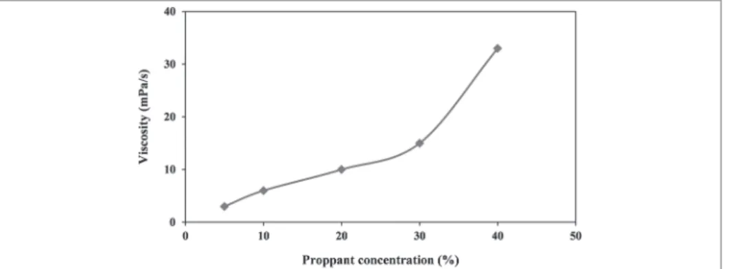
water-based gum fracturing fluid, respec-tively. Ceramsite was used as the common proppant, with an average diameter of 0.6 mm, and a density of 3.29 g/cm3. The self-suspending proppant was prepared with a density of 2.05 g/cm3, and the average diameter of the proppant was 0.6 mm. The viscosity of the fluid increases with the dissolution of the surface coating of the self-suspending proppant, as shown in Figure 2. The viscosity of the PLF ranged from 1 mPa·s to 35 mPa·s as the self-suspending proppant concentration
ranged from 0-40%.
Experimental procedures: The frac-turing fluid was made up in the mixing tank with a certain viscosity, pumped into the pipes and the simulated fracture, and the fluid filled the fracture. The proppant was mixed into the fracturing fluid in the tank to obtain the PLF with a certain proppant concentration. Then the PLF was propelled into the fracture and circled in the system until the flow was stable and no proppant settled. The time and the evolution of the PLF were recorded in videos and images.
Two comparative experiments were conducted, and the initial param-eters were set as follows: Case I: The viscosity of the fracturing fluid was 27 mPa·s, the mass and mass fraction of proppant were 20 kg and 20%, re-spectively. The inlet flow of the PLF was 4.9 m3/h (flow velocity was 22.7 cm/s). Case II: The initial viscosity of the frac-turing fluid (water) was about 1 mPa·s, the mass and mass fraction of proppant were 6.5 kg and 5%, respectively. The inlet flow of the PLF was 8.1 m3/h (flow velocity was 37.5 cm/s).
Figure 2 The viscosity of PLF with proppant concentration.
3. Results and discussion
The basic phenomena of the PLF flow were characterized as follows: Two zones were formed at the inlet once the PLF was propelled into the fracture, denominated: proppant tumbling zone and suspending zone (Figure 3a). In the proppant tumbling zone, the proppant tumbled towards the end of the fracture; the settling and rolling
of particles went into a dynamic equilibri-um progressively. In the proppant suspend-ing zone, the proppant was in suspended state. With the continuous injection of the PLF, two new zones occurred in the frac-ture, denominated: proppant bank zone and free zone (Figure 3b). In the proppant bank zone, the proppant kept immovable,
particles settled down in the fracture due to gravity and a sand bed formed at the bot-tom. While in the free zone, few proppants existed, when the PLF reached the outlet of the fracture, and then a new circle was started and repeated, accompanying the decrease of the proppant concentration in the PLF (Figure 3c).
Figure 3 The evolution of the proppant distribution
in Case II 3a -Proppant distribution after 2s%3B 3b - Proppant distribution after 11 s%3B 3c - Proppant distribution after 22s.
The formation of the four zones can be described in the following mechanical views: In the laminar flow status, three
main forces i.e. gravity, buoyancy and viscous drag, are applied on the proppant grains. Viscous drag exists when there is a
velocity difference between the fluid and solid. The motion equation of a single spherical particle can be expressed as:
(
)
3 p
s l D0
6
d
g
F
π
ρ
−
ρ
=
where CD is the drag coefficient, FD0 is the viscous drag, dp is the diameter of particle, ρS and ρ1 are the particle and
fluid densities, respectively. Because
the density of the proppant is greater than the fluid, the proppant settles in the fluid, and the settling velocity increases until the viscous drag equals
the difference between the gravity and the buoyancy. The settling velocity can be expressed as:
(2) (1)
(
)
12p s l
s D
4
3
d
g
u
C
ρ
ρ
ρ
−
⎡
⎤
= ⎢
⎥
⎣
⎦
Finally, the proppant settles on the bottom of the fracture, and the proppant bank zone forms (Figure 4). Jet effect is predominant at meshes of the inlet, and boundary layers form at the sides of the model; therefore,
turbulence flow occurs close to the inlet and sides of the model. The en-ergy of the vortexes is related to the velocity and viscosity of the PLF flow. Within the affected zone of vortexes, the Saffman force equals even exceeds
the difference between the gravity and buoyancy, and the solid grains suspend or tumble in the fluid, leading to the formation of the proppant suspending zone and tumbling zone, as shown in Figure 5.
Figure 4
Settling process of proppant particles.
Figure 5
The vortexes caused by jet effect near the inlet.
The proppant concentration of the PLF decreases with the flow and settlement of proppant, leading to the expansion of the proppant bank. The flow area decreases due to the growing of the bank, while the velocity of PLF flow increases until the final equilibrium status is reached. As shown in Figure 3,
the thickness of bank zone increases progressively with the increase of time. In Case I, the distribution of the prop-pant in the fracture was distinguishingly discontinuous. The proppant settled more rapidly, after about 10 minutes, the PLF flow was stable, almost all the proppants settled and formed a porous
medium, and the thickness was about 10 cm, being homogenous along the length of the fracture. In Case II, the thickness of the proppant bank was larger than that of Case I, though the mass decreased to 1/3 of that in Case I (As in Figure 6). The results comparison of two cases are listed in Table 1.
Figure 6
The thickness distribution of the proppant bank 6a - Spatial configuration in the simu-lated fracture in Case I%3B 6b - Spatial con-figuration in the simulated fracture in Case II%3B 6c - Thickness distribution alon.
(a) (b)
(c)
195
Case
Viscosity of the fracturing
fluid
Type of
proppant Density proppantMass of
Mass fraction
of proppant
Inlet flow
Mean thickness
of proppant I 27 mPa·s Ceramsite 3.29 g/cm3 20 kg 20% 4.9 m3/h 10 cm
II 1 mPa·s Self-sus-pending 2.05 g/cm3 6.5 kg 5% 8.1 m3/h 16 cm
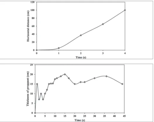
Due to the lower viscosity of water than in Case I, most of the self-suspending proppant settled more rapidly at the inlet of the fracture. An initial proppant bank of about 15 cm in thickness was formed in 1 s (Figure 8). Then the incoming prop-pants were pushed forward and settled, leading to the increase of the proppant bank length at a velocity of about 30 cm/s (as in Figure 7). During the PLF flow, the surface coating of the proppant was dissolving, the diameter of the self-suspending proppant decreased, and the
density increased a little. The proppant bank zone and suspending zone were the two main types of proppant distribution in the fracture. The proppant could be in a suspending status as a thick layer on the bottom of the fracture, similar to a fluidi-zation bed, which favored the supporting of the fracture. The coupling problem of the physical transition of the proppant and PLF flow should be considered to predict the transportation efficiency and effective laying.
The thickness of the proppant bank
(partially belonged to the suspending zone) increased with the expansion and circling of the PLF flow in 15 s, then the thickness decreased a little (As in Figure 8). The main reason is that the water solution of the coating increases the viscosity of the fluid, the volumetric density of the proppant increases 5%-10%, and the diameter of the proppant decreases from 605 μm to 585 μm. The changes in the gravity, buoyancy and viscous drag cause the final loose laying of the self-suspending proppant.
4. Conclusions
The PLF flow in a single fracture is investigated in two comparative experi-ments. The self-suspending proppant is considered to improve the transportation and deposition of the proppant.
Four zones such as the proppant
bank, suspending, tumbling, and free zones are formed during the PLF flow. The size and distribution of the zones change with the diameter and density of the proppant, and the viscosity of the PLF.
The self-suspending proppant
increases the thickness of proppant suspending and bank zone. The self-suspending PLF is effective in support-ing hydraulic fractursupport-ing. The couplsupport-ing processes and mechanism are interesting and worth researching.
Acknowledgement
This research is supported by the Foundation (No. G5800-15-ZS-WX047) of State Key Laboratory of
Shale Oil and Gas Enrichment Mecha-nisms and Effective Development and the National Science and Technology
Major Project of the Ministry of Sci-ence and Technology of China granted No.2016ZX05046-003.
Figure 8 The thickness of the self-suspending proppant bank with time.
Figure 7 The development of length of the self-suspending proppant bank.
Received: 18 September 2016 - Accepted: 15 December 2017.
References
ABDULRAHMAN A. Dimensionless groups for interpreting proppant transport in hydraulic fractures. Management & Production Engineering Review, v. 357, n. 2, p. 324-335, 1999.
BABCOCK, R.E., PROKOP C.L., KEHLE R.O. Distribution of propping agents in vertical fractures. Drilling and Production Practice, New York, 1 January, 1967. CLEAR P., WRIGHT C.A., WRIGHT T.B. Experiment and modeling evidence
for major changes in hydraulic fracturing design and field procedures. 1991. (SPE-21494).
CLEARY M.P., FONSECA, A. Proppant convection and encapsulation in hydraulic fracturing: Practical implications of computer and laboratory simulation. 1992. (SPE, 24825).
DONTSOV E., PEIRCE, A. Slurry flow, gravitational settling and a proppant transport model for hydraulic fractures. Journal of Fluid Mechanics, n.760, p. 567-590, 2014.
EISSA M.E., SHOKIR K.S., ABDULRAHMAN, A. A. Experimental and numerical investigation of proppant placement in hydraulic fractures. 2007. (SPE-107927). KERN, L.R., PERKINS, T. X., WYANT, R.E. The mechanics of sand movement in
fracturing. Journal of Petroleum Technology, v.11, n.7, p.55-57, 1959.
MICHAELIDES. E., EBRARY, I. Particles, bubbles & drops: their motion, heat and mass transfer. Singapore: World Scientific, 2006.
MCCLURE, M., HOME, R. N. Discrete fracture network modeling of hydraulic sti-mulation: coupling flow and geo-mechanics. Switzerland: Springer International Publishing, 2013.
MCCLURE, W.M., BABAZADEH, M., SHIOZAWA, S. et al. Fully coupled hydro-mechanical simulation of hydraulic fracturing in 3D discrete fracture networks.
SPE Journal, 2016. (SPE-173354-PA).
STOKES, G., G. On the effect of the internal friction of fluids on the motion of pendulums. Transactions of the Cambridge Philosophical Society, v.9, n.8, p.46-52, 1850.
SHIOZAWA, S., MCCLURE, M. Simulation of proppant transport with gravitational setting and fracture closure in a three-dimensional hydraulic fracturing simulator.
Journal of Petroleum Science and Engineering, n.138, p.298-314, 2016.
TSAI, K., FONSECA, E., DEGALEESAN, S. Advanced computational modeling of proppant settling in water fractures for shale gas production. 2012. (SPE-151607). VANDERHOEF, M. A., BEETSRA, R., KUIPERS, J. A. M., Lattice-Boltzmann
simulations of low-Reynolds-number flow past mono- and bi-disperse arrays of spheres: results for permeability and drag force. Journal of Fluid Mechanics,
n.528, p.233-254, 2005.