DOI: http://dx.doi.org/10.1590/2446-4740.07716 Volume 33, Number 2, p. 144-155, 2017
Introduction
Spinal cord injury (SCI) is a consequence of damage to axons that pass along the spinal cord, generally caused by automobile accidents, sports activities, gun shots, falls and diseases like tumors (Badran and Moussa, 2005; Masdar et al., 2012).
Functional electrical stimulation (FES) is a technique that aims to minimize health problems after SCI and has been successfully applied to rehabilitation treatment (Hsueh and Chen, 2012). Studies inform that electrical
stimulation can strengthen muscles (Bélanger et al., 2000). In addition to aiding persons with limited neural control (Moreno-Aranda and Seireg, 1981) or nonexistent limb control, FES application promotes beneits to ventilation, intestinal, bowel and sexual functions as well as it avoids muscle atrophy, spasticity, pressure ulcers, thrombosis, contractures and bone demineralization (Cheng et al., 2004).
The fundamentals of a typical FES device are based in turning low voltage/current amplitude stimulatory pulses generated by special circuits into high amplitude signals that can be applied to the neuromuscular tissue of a (partially) paralyzed limb and promote its rehabilitation (Laguna et al., 2011). The responsibility for ampliication and delivery to tissues is ultimately assigned to the “output stage” or “driving stage”. The requirement for such high amplitude signals is due to high human skin impedance that can vary between 500 Ω and 2 kΩ (Xu et al., 2011). Regarding circuit topology, the output stage is the last module in a typical FES device and the only module in which software cannot replace hardware implementation. The output stage has the duty of transferring energy
Power ampliier circuits for functional electrical stimulation systems
Delmar Carvalho de Souza
1, Marcelo do Carmo Gaiotto
2, Guilherme Nunes Nogueira Neto
2,
Maria Claudia Ferrari de Castro
3, Percy Nohama
1,2*
1 Federal Technological University of Paraná, Curitiba, PR, Brazil. 2 Pontiical Catholic University of Paraná, Curitiba, PR, Brazil.
3 University Center of the Educational Foundation “Padre Sabóia de Medeiros”, São Bernardo do Campo, SP, Brazil.
Abstract Introduction: Functional electrical stimulation (FES) is a technique that has been successfully employed in rehabilitation treatment to mitigate problems after spinal cord injury (SCI). One of the most relevant modules in
a typical FES system is the power or output ampliier stage, which is responsible for the application of voltage
or current pulses of proper intensity to the biological tissue, applied noninvasively via electrodes, placed on the
skin surface or inside the muscular tissue, closer to the nervous ibers. The goals of this paper are to describe and
discuss about the main power output designs usually employed in transcutaneous functional electrical stimulators as well as safety precautions taken to protect patients. Methods: A systematic review investigated the circuits of papers published in IEEE Xplore and ScienceDirect databases from 2000 to 2016. The query terms were “((FES or Functional electric stimulator) and (circuit or design))” with 274 papers retrieved from IEEE Xplore and 29 from ScienceDirect. After the application of exclusion criteria the amount of papers decreased to 9 and 2 from IEEE Xplore and ScienceDirect, respectively. One paper was inserted in the results as a technological contribution to
the ield. Therefore, 12 papers presented power stage circuits suitable to stimulate great muscles. Discussion: The retrieved results presented relevant circuits with different electronic strategies and circuit components. Some of them considered patient safety strategies or aimed to preserve muscle homeostasis such as biphasic current application, which prevents charge accumulation in stimulated tissues as well as circuits that dealt with electrical impedance variation to keep the electrode-tissue interface within an electrochemical safe regime. The investigation revealed
a predominance of design strategies using operational ampliiers in power circuits, current outputs, and safety
methods to reduce risks of electrical hazards and discomfort to the individual submitted to FES application.
Keywords Functional electrical stimulator, SCI, Output stage, Power stage, Artiicial gait rehabilitation.
This is an Open Access article distributed under the terms of the Creative Commons Attribution License, which permits unrestricted use, distribution, and reproduction in any medium, provided the original work is properly cited.
How to cite this article: Souza DC, Gaiotto MC, Nogueira GN No, Castro MCF, Nohama P. Power amplifier circuits for functional electrical stimulation systems. Res Biomed Eng. 2017; 33(2):144-155. DOI: 10.1590/2446-4740.07716.
*Corresponding author: Pontiical Catholic University of Paraná,
Rua Imaculada Conceição, 1155, Prado Velho, CEP 80215-901, Curitiba, PR, Brazil. E-mail: [email protected]
to the stimulated tissues safely and without causing distortions to low amplitude pulses generated by the previous stages. The constructive aspects involved in the design of an electrical stimulator often raise questions regarding circuit topology, technology and components. Therefore, this paper aims to present and discuss the state of the art concerning the technologies used on output stages of FES systems in order to control lower limb functional movements that are suitable and safe for treating people with SCI or stroke.
Neuromuscular electrical stimulator
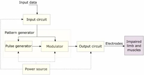
The output stage of an electrical stimulator does not act alone. Indeed, most of the signal generation has to do with other modules that are part of the FES device. Generally, other modules properly format low-level voltage signals before they reach the output stage. Figure 1 presents the main modules of a typical FES device, including:
• Input circuitry: ampliies electrical biosignals acquired from user’s skin and joints that are often very small in amplitude and noisy; therefore, this module also involves iltering signals. The data carried by input signals can come in as external references or from (closed-loop) internal feedback paths. Servomechanisms use feedback in order to control one or more parameters that vary over time (Distefano et al., 2012; Ogata, 1997; Webster, 1989). A FES system may allow its operator to deine a desired joint angle, and the feedback system provides adjustments to stimulus amplitude to follow the reference angle; • Pulse generator: is responsible for producing
a sequence of low amplitude electrical pulses. Generally, it consists of oscillator circuits or microcontroller whose output pulses have
controllable amplitude, width and frequency. Pulses are modiied by the waveform modulator module (Cheng et al., 2004; Webster, 1989; Xu et al., 2011);
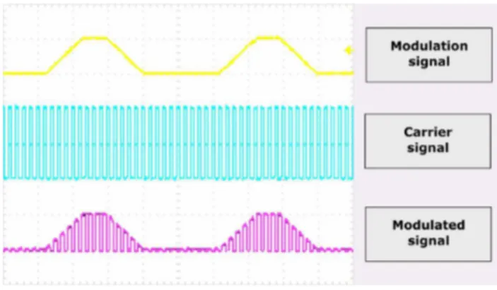
• Waveform modulator: generates a signal that modulates the high frequency carrier signal, produced by the pulse generator. The interaction between “pulse generator” and “modulator” modules allows producing low amplitude waveforms that must be suitable (i.e. with adequate format and amplitude) to stimulate target muscles after their ampliication in the output stage (Figure 2) (Khosravani et al., 2011; Laguna et al., 2011; Wu et al., 2002);
• Power/output stage: ampliies low-level stimulatory signals to high level voltage/current;
• Power supply: provides external energy for proper regulation and operation of the FES electronic system. Generally, either residential/industrial mains or batteries supply power to the system. Rechargeable batteries have the advantage of being portable and relatively safe to use.
The output stage
Generally, the output stage of a typical FES device is right after the modulator and immediately before the electrodes. It consists of a set of electronic components arranged for commuting voltage or current signals that provides adequate energy to stimulate the neuromuscular tissue. As it is the last stage and it is going to be in contact with the skin and tissues via leads and electrodes, this stage involves the implementation of safety precautions. The application of electrical energy to muscles can occur in two modes: constant voltage or constant current. Determining this feature in the circuit implies choosing
a particular topology for the output signal (Mottaghi and Hofmann, 2015).
Current can low in and out of the tissue depending on the signal reference. Therefore, depending on the current direction, the applied signal can be monophasic or biphasic, consequently, requiring a monophasic or biphasic output. Monophasic outputs allow only unidirectional current low, creating charge imbalances in the tissue. A biphasic output allows both applying to and taking out of the tissue electrical charges, preventing charge accumulation that is harmful to the subject, mainly around the application site (Xu et al., 2011).
The FES device can have one or more stimulatory output stages, usually called channels, each one responsible for the stimulation of a different muscle. Multi-channel FES devices are those with more than one channel.
Current versus voltage
The design of a FES device does not depend uniquely on electronic schematics. Human skin impedance is high and variable along the application time. It varies between individuals as a function of temperature, stimulus frequency and application time (Hsueh and Chen, 2012). Therefore, even if stimulation voltage is constant there may be charge imbalance due to Ohm’s law. If impedance varies then the current applied to the neuromuscular tissue also varies, consequently, the same happens with the applied charge. Therefore, the design of some FES devices has current-controlled output stages. The amount of charge can thus be safely determined, more precisely controlled (Hsueh and Chen, 2012), and this is important to keep the electrode–tissue interface within an electrochemically safe regime (Merrill et al., 2005). This occurs because the electric ield does not
depend on electrode polarization when regulated current causes the stimulus (Zonghao et al., 2010).
Studies show that there are many important and relevant aspects for building such a specialized device. However, after prospecting the main technical portals, we did not ind a technical or bibliographical review related to the topology of stimulatory circuits focusing on the output stage. This stage is important because its design must follow the way energy is going to be controlled and/or delivered to the patient. Regarding safety, it is the last stage of a typical FES device, and cables and electrodes connect it to the person directly.
Methods
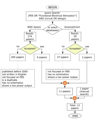
The search was performed in March 3rd 2016 on
IEEE Xplore and ScienceDirect databases. Two sets of search terms deined the queries (Figure 3):
1) “electrical stimulator” AND “design”;
2) “FES” OR “functional electric stimulator” AND “circuit” OR “design”.
We focused on papers describing output stage circuits suitable to the stimulation of great muscles, as those of lower limbs, with transcutaneous electrodes. The inclusion criteria were to present (i) circuit schematics and (ii) detailed functional description. The exclusion criteria were systems having characteristics such as (a) low voltage FES signals (below 100 V); (b) low current output (below 100 mA); (c) absence of circuit schematics; (d) publication before year 2000, and (e) working with implantable electrodes. Therefore, more than merely read the abstracts, the papers were thoroughly studied in order to determine the desired characteristics.
Results
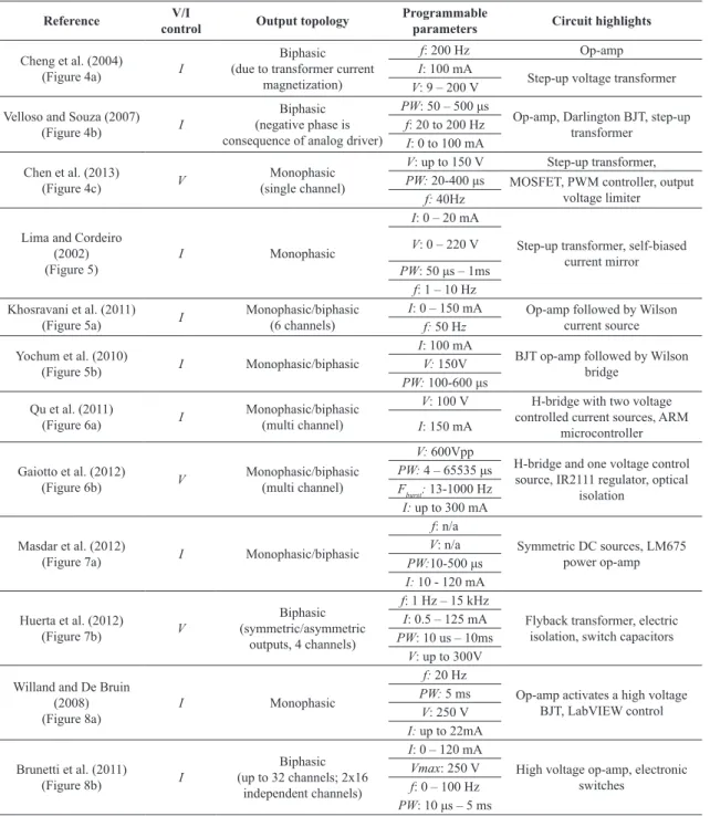
This section begins with Table 1 that summarizes the general information obtained about output stages in the selected papers. Each line presents relevant aspects for this review: nature of the applied energy (voltage/current), topology, and the main components used in the circuits.
Descriptive analysis
The output stages described in Cheng et al. (2004), Velloso and Souza (2007), and Chen et al. (2013) present one common characteristic: a transistor switches the step-up transformer’s primary (Figure 4). As a result, a high-pulsed voltage develops in the secondary energizing the attached electrodes causing current low through the load.
Khosravani et al. (2011), Yochum et al. (2010), and Lima and Cordeiro (2002) designed circuits based on current mirror to regulate the output current (Figure 5).
In Khosravani et al. (2011) the output stage consists of high amplitude supplied Wilson current mirror and H-bridges to which the leads are connected (Figure 5a). The Wilson current mirror regulates the “main current” previously formatted by a digital-analog converter (DAC). The transistors in the H-bridge operate in the cut and saturation regions, activated by a microcontroller. They have six independent stimulatory channels, monophasic and biphasic pulse outputs that can reach 150 mA.
The circuit shown in Figure 5b has a symmetric topology of two Wilson current mirrors to generate biphasic pulses with output current that is independent of load. The use of current mirrors allows establishing the output current by means of a reference current (Yochum et al., 2010).
Lima and Cordeiro (2002) present a driving stage that consists of a Cascode voltage-to-current converter (Figure 5c). Load current “I skin” is constant and controlled
Table 1. Summary of output stage circuit details described in the retrieved papers.
Reference controlV/I Output topology Programmable parameters Circuit highlights
Cheng et al. (2004)
(Figure 4a) I
Biphasic (due to transformer current
magnetization)
f: 200 Hz Op-amp
I: 100 mA
Step-up voltage transformer
V: 9 – 200 V
Velloso and Souza (2007) (Figure 4b) I
Biphasic (negative phase is consequence of analog driver)
PW: 50 – 500 μs
Op-amp, Darlington BJT, step-up transformer
f: 20 to 200 Hz
I: 0 to 100 mA Chen et al. (2013)
(Figure 4c) V
Monophasic (single channel)
V: up to 150 V Step-up transformer,
PW: 20-400 μs MOSFET, PWM controller, output voltage limiter
f: 40Hz
Lima and Cordeiro (2002) (Figure 5)
I Monophasic
I: 0 – 20 mA
Step-up transformer, self-biased current mirror
V: 0 – 220 V
PW: 50 μs – 1ms f: 1 – 10 Hz Khosravani et al. (2011)
(Figure 5a) I
Monophasic/biphasic (6 channels)
I: 0 – 150 mA Op-amp followed by Wilson current source
f: 50 Hz
Yochum et al. (2010)
(Figure 5b) I Monophasic/biphasic
I: 100 mA
BJT op-amp followed by Wilson bridge
V: 150V
PW: 100-600 μs
Qu et al. (2011)
(Figure 6a) I
Monophasic/biphasic (multi channel)
V: 100 V H-bridge with two voltage controlled current sources, ARM
microcontroller
I: 150 mA
Gaiotto et al. (2012)
(Figure 6b) V
Monophasic/biphasic (multi channel)
V: 600Vpp
H-bridge and one voltage control source, IR2111 regulator, optical
isolation
PW: 4 – 65535 μs Fburst: 13-1000 Hz
I: up to 300 mA
Masdar et al. (2012)
(Figure 7a) I Monophasic/biphasic
f: n/a
Symmetric DC sources, LM675 power op-amp
V: n/a
PW:10-500 μs I: 10 - 120 mA
Huerta et al. (2012)
(Figure 7b) V
Biphasic (symmetric/asymmetric
outputs, 4 channels)
f: 1 Hz – 15 kHz
Flyback transformer, electric isolation, switch capacitors
I: 0.5 – 125 mA
PW: 10 us – 10ms
V: up to 300V
Willand and De Bruin (2008) (Figure 8a)
I Monophasic
f: 20 Hz
Op-amp activates a high voltage BJT, LabVIEW control
PW: 5 ms
V: 250 V
I: up to 22mA
Brunetti et al. (2011)
(Figure 8b) I
Biphasic (up to 32 channels; 2x16
independent channels)
I: 0 – 120 mA
High voltage op-amp, electronic switches
Vmax: 250 V
f: 0 – 100 Hz
PW: 10 μs – 5 ms
f – frequency; I – current; V – voltage; Vmax – maximum voltage; PW – pulse width; n/a – not available.
by the MOSFET and Cascode resistor. Stimulus intensity is set through resistor R5.
The circuit proposed by Qu et al. (2011) has an H-bridge output stage with four controlled switches and a voltage-to-current converter for each channel (Figure 6a). This arrangement can supply electrodes with biphasic pulses or with arbitrary waveforms. Voltage-controlled current sources provide regulated output current even with skin impedance variation.
connected. Aiming to reach more precision, half bridge drivers control the H-bridge. This arrangement increases the possibilities for activating outputs and generating monophasic/biphasic pulses. The maximum monophasic and biphasic voltage amplitudes are 300 and 600 V, respectively.
Masdar et al. (2012) inserted a voltage-to-current converter (LM675 op-amp, current output up to 3A) in the output stage of the FES device. The LM675 receives pulses sent by DAC determining whether current on
a 1 kΩ load would be positive or negative. Figure 7a presents the current-controlled output.
In Huerta et al. (2012), the output stage consists of a voltage step-up transformer (lyback) where an electronically switched DC source supplies the primary (Figure 7b). The output current amplitude results from the lyback control that also supplies the switch-capacitors (SCs). In this design, Rsense resistor and an op-amp monitor the load current. An analog-digital converter (ADC) digitally converts the current into data that are compared to a reference value, thus, allowing control.
Figure 4. Transformer based circuits [(a) extracted from Cheng et al. (2004), (b) extracted from Velloso and Souza (2007), and (c) extracted from Chen et al. (2013)].
Figure 6. H-bridge based circuits [(a) extracted from Qu et al. (2011), and (b) modiied from Gaiotto et al. (2012)].
The cathodic pulses generated by the transformer and by anodic pulses provided by the SCs generate the biphasic stimuli. The electronically controlled capacitors can produce a zero liquid charge in stimulated tissues.
The transformer provides voltages up to 300V. Optocouplers isolate the stimulator circuits from control circuits.
Willand and De Bruin (2008) show an output stage that is built with high voltage bipolar transistors (TIP 50) activated by an op-amp to guarantee constant current. A LabVIEW program formats monophasic waveforms that pass throw the isolation barrier and drive Q1 (Figure 8a). However, the authors can adapt the circuit to an H-bridge design in order to generate biphasic pulses.
The output stage of Brunetti et al. (2011) consists of current source based on a transconductance ampliier and a high voltage op amp (Figure 8b).
Brunetti et al. (2011) proposed the use of distributed electrodes to reduce current concentration and reduce fatigue and pain, as well as to improve muscle selectivity. The electrical stimulator was built with a high voltage op-amp (PA78) acting as a voltage-to-current converter, that can produce monophasic or biphasic currents, depending on the input pulses (Vin). Four AA batteries supply the stimulator. Concerning safety, load remains connected to 0 V when the signal equals to 0 (zero), reducing the risk of being improperly supplied.
The stimulator design allows the connection of more leads. Each output stage has a DC-DC boost converter that produces a high voltage, a microcontroller for communication with the CPU from which it receives data to generate the stimulatory pulses.
Discussion
Three constructive aspects were identiied in FES output circuits that could functionally stimulate lower limbs: (i) voltage elevation on load, (ii) voltage or current regulation and (iii) the generation of biphasic current in order to protect tissues and electrodes from accumulated charges.
Regarding voltage elevation, in some electrical circuits the step-up transformer is directly in the stimulator output stage. Papers describing circuits consisting of op-amps showed no voltage source details, except Gaiotto et al. (2012) who introduced details regarding the CC-CC converter employed in their output stage.
Although frequently used to step up voltage, transformers have disadvantages like their dimensions, electromagnetic interferences, power consumption, and in case the device is intended as versatile in programming, limited amplitude range (due to ixed turns ratio), and limited frequency of operation (Masdar et al., 2012). Such a transformer appears either in the power supply (Gaiotto et al., 2012) or directly in the stimulator output stage as proposed by Chen et al. (2013) who presented a clipping circuit installed in the transformer’s secondary aiming to limit voltage to 150V. However, the disposition of rectiier diodes (cathodes connected with each other) does not clip the signal to limit voltage as afirmed (Figure 4). One can notice in Cheng et al. (2004) that the provided protection given by transformer’s galvanic isolation is lost due to the feedback link. Gaiotto et al. (2012) inserted optocouplers in the feedback path, therefore improving circuit safety.
Cheng et al. (2004) and Velloso and Souza (2007) used the same output stage circuit but with few signiicant changes. In the analyzed circuits, the output current can be regulated by means of feedback current applied to a comparator (Figure 4b) or using current mirror to make output current independent on load impedance variations. Lima and Cordeiro (2002), Yochum et al. (2010) and Khosravani et al. (2011) use these resources (Figure 5). The feedback loses the advantage of galvanic isolation provided by the output isolator transformer. Gaiotto et al. (2012) use optocouplers to avert such inconvenience.
Lima and Cordeiro (2002) used a Cascode current mirror to ix a monophasic current on load. Yochum et al. (2010) used current mirror in a symmetric set to ix current and also to create a biphasic current and reduce the risks of burning the skin and accumulate charges in the tissues. Khosravani et al. (2011) employed a current mirror to ix the load current and to let the H-bridge to create a biphasic current and reduce charge accumulation. In addition, a sole current mirror ixes current to all channels. Each channel has an H-bridge with four transistors activated by a microcontroller. In the work of Yochum et al. (2010), since the output stage is formed by a set of symmetric current mirrors, the set is much more complex when a high number of channels is needed when comparing with Khosravani et al. (2011)’s proposal. In the later study increasing the number of channels means including additional H-bridge and control lines, whereas in the former study increasing a channel means replicating the whole output stage. The proposal of Lima and Cordeiro (2002) is similar to Yochum et al. (2010), but with the disadvantage of generating only monophasic currents (Figure 5).
The use of an H-bridge has the main goal of generating biphasic currents and getting its beneits. Gaiotto et al. (2012) designed a circuit concerning with the coordination of the switching transistor due to differences between complementary transistors as well as the gate capacitances, which can cause a momentary short circuit (Figure 6). To achieve this goal, they used IR2111 half-bridge drivers applied to each pair of MOSFETs. This component is a half bridge driver and it has an internally set deadtime protection that prevents shoot-through. The high voltage is adjusted before the H-bridge. Conversely, Qu et al. (2011) employed voltage-to-current converters in each branch of the H-bridge aiming to maintain the current constant and independent on load. Although they did not mention whether H-bridges are complementary or not (Figure 6), an ARM microcontroller with internal deadtime protection controlled the switches on the H-bridge as well as two voltage-to-current converters (Vin) generating pulses at different frequency, amplitude and width. Since high voltage is applied to the H-bridge in this later circuit, and MOSFETs have to support the
energy during Vin current modulation, it is acceptable to state that the proposal of Gaiotto et al. (2012) is slightly safer regarding operation. Another difference is the maximum allowable current that is greater in the work of Gaiotto et al. (2012).
Khosravani et al. (2011) also used H-bridge to create biphasic current over load (Figure 5). A microcontroller independently controlled MPSA42 transistors used as switches. No information is provided on attention required on the switching considering the transistors are not complementary. Brunetti et al. (2011) used an H-bridge to generate monophasic and biphasic pulses; however, they also employed a matrix of analog high voltage microswitches (MAX14802) to stimulate muscles in a distributed fashion. Simultaneous channels could apply the same signal to different muscles. They also stated that a special technique was developed in the circuit to avoid a maximum voltage be obtained (250V) to prevent accidents when the circuit is opened (ininite load) because the load is not directly connect to ground but always to a high voltage point. The output stage of Willand and De Bruin (2008) is monophasic, although H-bridge coniguration could produce bipolar signals.
Other solutions in the literature can generate biphasic currents without the use of H-bridges or symmetric compositions in the output stage. Masdar et al. (2012) use a LM675 power op-amp activated by a DAC and microcontroller (Figure 7a) to generate biphasic pulses with variable amplitudes. Huerta et al. (2012) used SC converters to obtain a zero net charge and protect the stimulated tissues (Figure 7b). The currents in SC low in opposite direction compared to the stimulation currents, thus reducing charge accumulation in the tissue. Microcontroller allows switches to close or open letting SC to charge or discharge.
Functional electrical stimulators may produce pulses of either controlled voltage or current applied to load. Two circuits (16.7%) used controlled voltage whereas 10 circuits (83.3%) used controlled current. Regarding studies that regulated current, one inds op-amps acting as voltage-to-current converters in 8 cases (66.7%), current mirrors in 3 cases (25%) and 1 case (8.3%) regulating lyback output (Huerta et al., 2012). Voltage-to-current converters control current output by means of voltage control. Wilson or Cascode current mirrors allow adjusting the current independently on load variation. Huerta et al. (2012) measured and compared the output stimulation current to reference voltages, and eventual variations were applied to the lyback.
to the input op-amp. Brunetti et al. (2011), Gaiotto et al. (2012), Khosravani et al. (2011) and Qu et al. (2011) employed H-bridges, whereas Yochum et al. (2010) used symmetrically arranged current mirrors.
Brunetti et al. (2011) presented the most compact and simple circuit when the stimulator requires multiple electrodes. It employs a high voltage op-amp that distributes current to an array of electronic switches (MAXI4802). Each electronic switch matrix can feed 16 electrodes. However, no information about the performance of the matrix is provided in the retrieved literature.
In spite of bringing useful information, the work published by Masdar et al. (2012) did not present complete circuit schematics and, therefore, it was not possible to explain the pulse generator circuit.
Conclusion and future perspectives
Twelve papers described output stage circuits that could meet the needs for stimulating the great muscles of human lower limbs and the inclusion criteria.
Performing this investigation revealed a complex task. Firstly, query terms could not be wide, because there are many circuits for electrical stimulation. This work focused on describing topologies and characteristics of stimulator circuits that could be the most relevant for the development of FES output stages. Secondly, although there are many FES devices that share the same principles, the way authors do or do not inform circuit and parameter details in a single retrieved paper limits the search as the one performed in this study. Moreover, we decided to divide the circuits by constructive aspects. Another classiication could be voltage controlled or current controlled circuits, and in each group divide by constructive aspects.
Important aspects of the retrieved circuits were described like those related to biphasic current generation that may reduce the undesirable effects of charge accumulation in the stimulated tissues. Symmetric circuits, H-bridges, SCs and referenced voltage control were some of the identiied strategies and circuits that provided such important safety characteristic. The presence of op-amps in the circuit is predominant and may indicate a tendency in its use in detriment of traditional components like transformers. However, this can be a result of the systematic review process.
Transformers frequently appear in voltage controlled output stages, easily step up voltages and when they have a center tap they can produce biphasic stimuli. H-bridges are a little more complex because one has to design the driver bridges and be careful with isolation deadtime. Considering pulse quality, H-bridges tend to produce square pulses independent on pulse duration, a
design decision on parameter setting that may limit the capabilities of transformer based output stages.
The review showed that integrated circuits have been used more frequently in different stages of stimulation circuits. They are in use as ampliiers, current-voltage converters, associated to H-bridges to generate biphasic currents, and current mirrors to overcome the effects of variations in skin impedance. In signal generation, the deinitions of frequency and pulse width usually are performed using microcontrollers or personal computers setting aside oscillatory circuits that generated pulses with little lexibility. Nowadays, miniaturized computers like Raspberry Pi, BeagleBone and Cubieboard occupy the area of a credit card. In spite of that, no application used these technologies in the retrieved papers. Transformers are still in use for voltage elevation and circuit isolation, however, their limitations do not provide them good perspectives anymore when one concerns the new integrative technologies that let integrated circuits consume less and less power. Possibly, in the case no technological advancements occur in this speciic area, transformers are going to be limited to switched power supplies.
The future seems to count more on completely programmable stimulators embedded in high power integrated circuits having high eficiency and occupying small volumetric space. Efforts have been made, as observed in Hsueh and Chen (2012), for low-power stimulators.
The knowledge of the stimulated muscle condition, as well as the residual charge mechanism, will allow designing more eficient electrodes, capable of stimulating the muscles precisely and at the adequate depth. The current intensity and the pulse formats can be person or muscle oriented, considering muscle variations throughout the day, reducing fatigue limitations and pain or eventual damage to the stimulated tissues. Safety precaution was an issue that appeared in all investigated circuits like equipment housing grounding, circuit isolation between electrodes, optical isolation in the feedback and data transfer paths, current limitation, emergency (cutoff) switches, etc. In the future, side by side with safety, low power consumption and lexibility in parameter settings will be at the highest priority.
Acknowledgements
References
Badran M, Moussa M. BioMEMS implants for neural regeneration after a spinal cord injury. In: Proceedings of the 2005 International Conference on MEMS, NANO and Smart
Systems (ICMENS’05); 2005; Alberta, Canadá. USA: IEEE;
2005. p. 89-90. http://dx.doi.org/10.1109/ICMENS.2005.31. Bélanger M, Stein RB, Wheeler GD, Gordon T, Leduc B. Electrical stimulation: can it increase muscle strength and reverse osteopenia in spinal cord injured individuals? Archives of Physical Medicine and Rehabilitation. 2000; 81(8):1090-8. PMid:10943761. http://dx.doi.org/10.1053/apmr.2000.7170. Brunetti F, Garay Á, Moreno JC, Pons JL. Enhancing functional electrical stimulation for emerging rehabilitation robotics in the framework of hyper project. In: Proceedings of the IEEE International Conference on Rehabilitation Robotics; 2011;
Zurich. USA: IEEE; 2011. p. 1-6. http://dx.doi.org/10.1109/
ICORR.2011.5975370.
Chen M, Wu B, Lou X, Zhao T, Li J, Xu Z, Hu X, Zheng X. A self-adaptive foot-drop corrector using functional electrical stimulation (FES) modulated by tibialis anterior electromyography (EMG) dataset. Medical Engineering & Physics. 2013; 35(2):195-204. PMid:22621781. http://dx.doi. org/10.1016/j.medengphy.2012.04.016.
Cheng KWE, Lu Y, Tong KY, Rad AB, Chow DHK, Sutanto D. Development of a circuit for functional electrical stimulation. IEEE Transactions on Neural Systems and Rehabilitation Engineering. 2004; 12(1):43-7. PMid:15068186. http://dx.doi. org/10.1109/TNSRE.2003.819936.
Distefano JJ 3rd, Stubberud AR, Williams IJ. Schaum’s outline of feedback and control systems. 2nd ed. New York: McGraw-Hill; 2012.
Gaiotto MCC, Nogueira-Neto GN, Krueger E, Magnani
CEF, Nohama P. Uma contribuição ao projeto de saída de estimuladores elétricos neuromusculares bifásicos. In: Anais do
XXIII Congresso Brasileiro de Engenharia Biomédica; 2012; Porto de Galinhas, PE, Brazil. Recife: Adaltech; 2012. p. 670-4. Hsueh YH, Chen GR. Design of high voltage digital-to-analog converter for electrical stimulator. In: Proceedings of the IEEE Asia Pacific Conference Circuits and Systems;
2012; Kaohsiung. USA: IEEE; 2012. p. 77-80. http://dx.doi.
org/10.1109/APCCAS.2012.6418975.
Huerta SC, Tarulli M, Prodic A, Popovic MR, Lehn PW. A universal functional electrical stimulator based on merged flyback-SC circuit. In: Proceedings of the 15th International Power Electronics and Motion Control Conference; 2012; Novi
Sad, Serbia. USA: IEEE; 2012; p. LS5a.3-1-LS5a.3-5. http://
dx.doi.org/10.1109/EPEPEMC.2012.6397471.
Khosravani S, Lahimgarzadeh N, Maleki A. Developing a stimulator and an interface for FES-cycling rehabilitation system. In: Proceedings of the 18th Iranian Conference of
Biomedical Engineering; 2011; Tehran. USA: IEEE; 2011.
p. 175-80. http://dx.doi.org/10.1109/ICBME.2011.6168550.
Laguna ZV, Cardiel E, Garay LI, Hernández PR. Electrical
stimulator for surface nerve stimulation by using modulated pulses. In: Proceedings of the Pan American Health Care
Exchanges; 2011; Rio de Janeiro. USA: IEEE; 2011. p. 77-82.
http://dx.doi.org/10.1109/PAHCE.2011.5871852.
Lima JA, Cordeiro AS. A low-cost neurostimulator with accurate pulsed-current control. IEEE Transactions on Biomedical Engineering. 2002; 49(5):497-500. PMid:12002182. http:// dx.doi.org/10.1109/10.995689.
Masdar A, Ibrahim BSKK, Jamil MMA, Hanafi D, Ahmad MKI, Rahman KAA. Development of wireless-based low-cost current controlled stimulator for patients with spinal cord injuries. In: Proceedings of the IEEE EMBS International Conference on Biomedical Engineering and Sciences; 2012;
Langkawi. USA: IEEE; 2012. p. 493-8. http://dx.doi.org/10.1109/
IECBES.2012.6498175.
Merrill DR, Bikson M, Jefferys JG. Electrical stimulation of excitable tissue: design of efficacious and safe protocols. Journal of Neuroscience Methods. 2005; 141(2):171-98. PMid:15661300. http://dx.doi.org/10.1016/j.jneumeth.2004.10.020.
Moreno-Aranda J, Seireg A. Electrical parameters for over-the-skin muscle stimulation. Journal of Biomechanics. 1981; 14(9):579-85. PMid:6174526. http://dx.doi.org/10.1016/0021-9290(81)90083-X.
Mottaghi S, Hofmann UG. Dynamically adjusted, scalable
electrical stimulator for excitable tissue. In: Proceedings of the 7th Annual International IEEE EMBS Conference on Neural
Engineering; 2015; Montpellier. USA: IEEE; 2015. p. 22-4.
http://dx.doi.org/10.1109/NER.2015.7146616.
Ogata K. Modern control engineering. 3rd ed. New Jersey: Prentice Hall; 1997.
Qu H, Wang T, Hao M, Shi P, Zhang W, Wang G, Lan N. Development of a network FES system for stroke rehabilitation. In: Proceedings of the 33rd Annual International Conference of the IEEE Engineering in Medicine and Biology Society;
2011; Boston. USA: IEEE; 2011. p. 3119-22. http://dx.doi.
org/10.1109/IEMBS.2011.6090851.
Velloso JB, Souza MN. A programmable system of functional electrical stimulation (FES). In: Proceedings of the 29th Annual International Conference of the IEEE EMBS; 2007;
Lyon. USA: IEEE; 2007. p. 23-6. http://dx.doi.org/10.1109/
IEMBS.2007.4352769.
Webster JG. Electronic devices for rehabilitation. John Wiley & Sons; 1989.
Willand MP, De Bruin H. Design and testing of an instrumentation system to reduce stimulus pulse amplitude requirements during FES. In: Proceedings of the 30th Annual International Conference of the IEEE Engineering in Medicine and Biology
Society; 2008; Vancouver. USA: IEEE; 2008. p. 2764-7. http://
dx.doi.org/10.1109/IEMBS.2008.4649775.
Wu HC, Young ST, Kuo TS. A versatile multichannel direct-synthesized electrical stimulator for FES applications. IEEE Transactions on Instrumentation and Measurement. 2002; 51(1):2-9. http://dx.doi.org/10.1109/19.989882.
Xu Q, Huang T, He J, Wang Y, Zhou H. A programmable multi-channel stimulator for array electrodes in transcutaneous electrical stimulation. In: Proceedings of the IEEE/ICME International Conference on Complex Medical Engineering;
2011; Harbin Heilongjiang. USA: IEEE; 2011. p. 652-6. http://
dx.doi.org/10.1109/ICCME.2011.5876821.
of the IEEE Engineering in Medicine and Biology Society;
2010; Buenos Aires. USA: IEEE; 2010. p. 4882-5. http://
dx.doi.org/10.1109/IEMBS.2010.5627264.
Zonghao H, Zhigong W, Xiaoying L, Wenyuan L, Xiaoyan S, Xintai Z, Shushan X, Haixian P, Cunliang Z. Design and
experiment of a neural signal detection using a FES driving system. In: Proceedings of the 32nd Annual International Conference of the IEEE Engineering in Medicine and Biology
Society; 2010; Buenos Aires. USA: IEEE; 2010. p. 1523-6.