Abstract
This work presents a new metamodel for reinforced panels under compressive loads, typically used in light-weight aircraft struc-tures. The metamodel represents a replicable cell structure of integrally machined panels. The presented formulation for con-ception is based on the synthesis of four stability criteria: section crippling, web buckling, flange buckling and column collapse. The aluminum alloy, a typical choice in modern aircraft industry, is selected and the structure is expected to work in the linear elastic domain. In order to evaluate the accuracy and to validate the analytical tool, the procedure is applied in the pre-sizing of the fuselage basic structural components of a 9-passenger executive aircraft. The pull-up maneuver, one of the critical load conditions in most of aircrafts, causes the maximum compressive stresses in lower fuselage panels. Finite element models are presented to the resulting fuselage configuration. The optimal configuration achieved through the application of the analytical tool yields to an innovative structure from those usually adopted in the aero-nautical industry. This structural configuration is presented and discussed. The developed metamodel proved to be effective, pre-senting satisfactory results with adequate accuracy for the initial stages of light-weight aircraft structure.
Keywords
structural optimization, structural stability, reinforced panels
A new metamodel for reinforced panels under
com-pressive loads and its application to the fuselage
con-ception
1 IN T R O D U C T IO N
Compressive loads acting on thin-walled structures, typically used in modern airframes, lead to failure by instability at stresses far below the material yielding compressive stress. In order to achieve the maximum structural efficiency, the designer and the structural engineer must arrange the structural elements wisely.
Alessandro Teixeira N eto* Flávio Luiz de Silva Bussam ra** H enrique Araújo de Castro e Silva
Instituto Tecnológico de Aeronáutica, CTA - ITA - , São José dos Campos - SP 12228-900, Tel.: 55-12-39475977; Brazil.
Received in 30 Jan 2013 In revised form 21 May 2013
Latin American Journal of Solids and Structures 11(2014) 223 – 244
Stiffened panels stability is a fundamental issue to structural designers. Wang (1997) present-ed an approximatpresent-ed method for lateral buckling of thin-wallpresent-ed members, taking into account the shear lag phenomenon. The buckling in airplane wings and fuselages with FSW – friction stir welding – is analyzed by Yoon et al. (2009), for the elastic-plastic material behavior, where nu-merical simulations with Abaqus (2006) finite element code is presented. The buckling analysis of fuselage stiffened panels loaded in compression is also simulated in Abaqus by Lynch et al. (2004). Non-linearity in the post-buckling thin-walled panels is discussed by Alinia et al. (2009) and Stamatelos et al. (2011). Analytical results in linear buckling of multi-stiffened panels under compression are presented by Bedair (1997), and Kolakowski and Teter (2000).
The airframe conception poses a complex duty to the product development engineering. It is expected to an efficient arrangement of the structural elements the capability to endure the loads that the aircraft are subjected to and also to cover its whole external surface at the least mass cost. It is a paradox, i.e. opposite expectations which can be overcame only by searching for the best compromise solution between light weight and high mechanical strength of the airframe. Analyses through the available computational packages are very helpful to the engineers. For many problems, however, a single simulation can take many minutes, hours, or even days to complete. As a result, routine tasks such as design optimization, design space exploration, sensi-tivity analysis and what-if analysis become impossible since they require thousands or even mil-lions of simulation evaluations.
One way of alleviating this burden is by constructing approximation models, such as surro-gate models and metamodels. They mimic the behavior of the simulation model as close as possi-ble while being computationally cheaper to evaluate. Surrogate models (Forrester et al., 2008; Toropov, 2013) are built using a data-driven, bottom-up approach. The exact, inner working of the simulation code is not assumed to be known (or even understood), solely the input-output behavior is important. So, a model is constructed based on modeling the response of the simulator to a limited number of intelligently chosen data points.
Latin American Journal of Solids and Structures 11(2014) 223 – 244
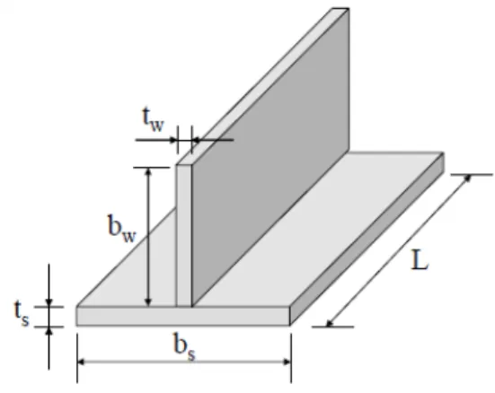
The present methodology for the pre-sizing of reinforced panels under compressive loads is based on the synthesis of four stability criteria in the simple metamodel depicted in Fig. 1. It represents a typical part of fuselage or wing box. For riveted reinforcements, it is clearly a rough approxima-tion model, but it is quite the exact representaapproxima-tion of modern integrally machined panels. The basic geometric parameters of the metamodel for the reinforced panel are: the panel length L, the web width bs and thickness ts, and the flange height bw and thickness tw. The panel is made of aluminum and is expected to work in the linear elastic domain. Four stability criteria are taken into account: section crippling, web buckling, flange buckling and column collapse.
The objective of this article is to present an efficient metamodel for reinforced panels under compressive loads, typically used in light-weight aircraft structures. Non-buckling panels are the design criteria herein adopted, so this method is not comparable with post-buckling methods of analysis, like effective width, global/local finite element methods or material equivalent plasticity for buckling of beams with flat webs.
Figure 1 Metamodel of the reinforced panel under compression.
To illustrate the use of the metamodel, two numerical applications are presented: a) the opti-mization of a reinforced flat panel under compressive load and b) the pre-sizing of a typical sem-imonocoque center fuselage of a 9-passenger aircraft, subjected to pull-up maneuver, which leads to the highest compressive loading in these lower fuselage panels. Both resulting structures are then modeled in MSC/Nastran (2004) finite element code in order to evaluate its behavior.
2 M ET A M O D EL A N A LY SIS
The following stability criteria are considered to the design of the metamodel presented in Fig. 1. The presented formulation is valid for aluminum alloys bars and panels.
2.1 Section Crippling
Latin American Journal of Solids and Structures 11(2014) 223 – 244
Fcc Fcy =β
gt2
A
⎛
⎝ ⎜⎜ ⎜⎜
⎞
⎠ ⎟⎟ ⎟⎟⎟ FEcy
⎡
⎣ ⎢ ⎢ ⎢
⎤
⎦ ⎥ ⎥ ⎥
m
(1)
where A is the cross-section area and t is the section thickness; m, g and
β
are dependent on the specific section shape. For a T-section with straight unloaded edges they result in g=3,β
=0.67 and m = 0.40. Since the panel geometry presents independent web thickness ts and flange thick-ness tw, the mean section thickness t is calculated as:t =twbw +tsbs
bw +bs (2)
Additionally Gerard (1958) recommends the cut-off of crippling allowable stress at 0.8 Fcy.
2.2 W eb and flange buckling
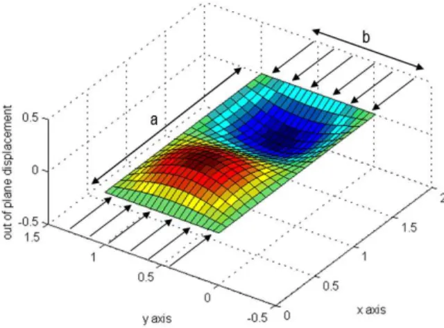
The web and the flange are considered as simple supported plates under axial loads in accordance with plate theory (Timoshenko and Gere, 1961). Although the most recent methods of post-buckling analysis include local stiffness of stringer and frame, this constraint condition is a choice to ease and to enhance the efficacy of the algorithm. The actual condition is known to be inter-mediary between simple supported and fixed for aeronautic skins and stringers. In conceptual or pre-sizing analysis, adopting the conservative condition; i.e., the simple supported condition, as-sures that the structure will be able to support the loads it has been designed for.
Figure 2 presents the geometry of a generic plate and its loads, where a and b are the element length and its width, respectively.
Latin American Journal of Solids and Structures 11(2014) 223 – 244
The buckling failure stress Fcbof a plate of thickness t under axial loading is given by
Fcb = Kc π2E 12 1
(
−ν2)
t b ⎛ ⎝ ⎜⎜ ⎜⎜ ⎞ ⎠ ⎟⎟ ⎟⎟ 2 (3)
where Kc is the buckling coefficient, which is dependent on the plate boundary conditions. For a simple supported plate, or the panel web, it can be calculated by
Kc = nb a + a nb ⎛ ⎝ ⎜⎜ ⎜⎜ ⎞ ⎠ ⎟⎟ ⎟⎟ 2 (4)
where n represents the sequence of integers from 1 up to infinity. So, Eq. (4) defines a series of Kc(n)values for each ratio a/b of the panel. The effective buckling coefficient Kc is the lowest value of this series; Kc = 4.0 can be assumed for practical purposes if a/b > 4.
Lundquist and Stowell (1941) presents the buckling coefficient Kc for a simple supported flange:
K
c = 6
π2
1−ν
(
)
+ b a ⎛ ⎝ ⎜⎜ ⎜⎜ ⎞ ⎠ ⎟⎟ ⎟⎟ 2 (5)The equalization of the buckling allowable stress of the web Fcb_web to the buckling allowable stress of the flange Fcb_flange yields
4 ts bs ⎛ ⎝ ⎜⎜ ⎜⎜ ⎞ ⎠ ⎟⎟ ⎟⎟ 2 = 6 π2
1−ν
(
)
twbw ⎛ ⎝ ⎜⎜ ⎜⎜ ⎞ ⎠ ⎟⎟ ⎟⎟ 2
+ tw
L ⎛ ⎝ ⎜⎜ ⎜⎜ ⎞ ⎠ ⎟⎟ ⎟⎟ 2 (6)
It must be observed that Eq. (6) leads to a dependency of the flange height bw on the remaining variables of panel geometry (L,bs,ts,tw) as a result of the concurrence of web and flange buckling design criteria, given by
b w =
tw
π
6 1
(
−ν)
4 tsb s ⎛ ⎝ ⎜⎜ ⎜⎜ ⎞ ⎠ ⎟⎟ ⎟⎟ 2
− tw
L ⎛ ⎝ ⎜⎜ ⎜⎜ ⎞ ⎠ ⎟⎟ ⎟⎟ 2 ⎡ ⎣ ⎢ ⎢ ⎢ ⎢ ⎤ ⎦ ⎥ ⎥ ⎥ ⎥ −1 2 (7)
2.3 Colum n collapse
Latin American Journal of Solids and Structures 11(2014) 223 – 244 F
cr = π2E
L' ρ
⎛ ⎝
⎜⎜⎜ ⎞⎠⎟⎟⎟2 (8)
where (L’/ρ) is the slenderness ratio, calculated by
L' ρ ⎛ ⎝ ⎜⎜ ⎜⎜ ⎞ ⎠ ⎟⎟ ⎟⎟ 2 =L 2A I x (9)
where the cross section area A of the panel is
A=t
wbw +tsbs (10)
and the inertia moment Ix is given by
Ix =ts 3
3 bs
−t w
(
)
+tw3 bw +ts
(
)
3−Ay2 (11)
with
y = 1
A ts2
2
(
bs −tw)
+tw2 bw +ts
(
)
2⎡ ⎣ ⎢ ⎢ ⎢ ⎤ ⎦ ⎥ ⎥ ⎥ (12)
2.4 T he optim ization procedure
The equivalent thickness teq given by
teq =A
bs =
bsts +bwtw
bs (13)
is directly related to the resulting mass of the panel. The compressive allowable stress Fc can be defined as the minimum stress between those evaluated, regarding each one of the four criteria previously discussed that concur to the structural stability, i.e.
Fc(L,bs,bw,ts,tw)=min F
cb_web,Fcb_flange,Fcc,Fcr
(
)
(14)Latin American Journal of Solids and Structures 11(2014) 223 – 244 max
{
Eff(L,bs,bw,ts,tw)}
Eff(L,bs,bw,ts,tw)=Fcbs
A ⎧ ⎨ ⎪⎪ ⎪⎪ ⎩ ⎪⎪ ⎪⎪ (15)
while the Design Space, usually found in typical wing and fuselage aluminum panels, is given by
0.1L≤bs ≤0.4L
0.005bs ≤ts ≤0.2bs
0.5ts ≤tw ≤2ts ⎧ ⎨ ⎪ ⎪ ⎪ ⎪ ⎪ ⎩ ⎪ ⎪ ⎪ ⎪ ⎪ (16)
It must be observed that Eq. (15) enables the panel geometry to reach the best compromise solu-tion between the maximum compressive allowable stress and the minimum mass, keeping coher-ence with the purposes of the dual nature of the problem.
2.5 O ptim ization results for A L7050-T 7451
Equations (15) and (16) are applied to the metamodel made of aluminum alloy AL7050-T7451 Plate 2.75in, a typical choice in modern aircraft industry. Its mechanical properties are: elasticity modulus in compression E = 73080 MPa, Poisson coefficient n= 0.33 and yield compressive stress
Fcy = 421 MPa. The optimization results are presented in Tab. 1. This set of results characterizes the panel geometry (tw/ts, ts/bs and tw/ts) and its respective compressive allowable stress Fc for a given value of the design parameter bs/L.
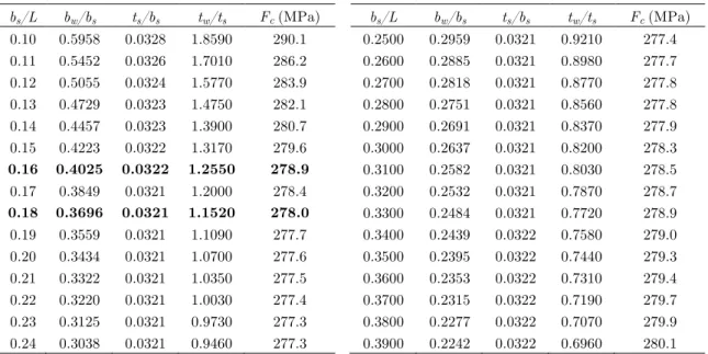
Table 1 Metamodel for reinforced panels under compressive loads, AL7050-T7451.
bs/L bw/bs ts/bs tw/ts Fc (MPa) bs/L bw/bs ts/bs tw/ts Fc (MPa)
0.10 0.5958 0.0328 1.8590 290.1 0.2500 0.2959 0.0321 0.9210 277.4
0.11 0.5452 0.0326 1.7010 286.2 0.2600 0.2885 0.0321 0.8980 277.7
0.12 0.5055 0.0324 1.5770 283.9 0.2700 0.2818 0.0321 0.8770 277.8
0.13 0.4729 0.0323 1.4750 282.1 0.2800 0.2751 0.0321 0.8560 277.8
0.14 0.4457 0.0323 1.3900 280.7 0.2900 0.2691 0.0321 0.8370 277.9
0.15 0.4223 0.0322 1.3170 279.6 0.3000 0.2637 0.0321 0.8200 278.3
0.16 0.4025 0.0322 1.2550 278.9 0.3100 0.2582 0.0321 0.8030 278.5
0.17 0.3849 0.0321 1.2000 278.4 0.3200 0.2532 0.0321 0.7870 278.7
0.18 0.3696 0.0321 1.1520 278.0 0.3300 0.2484 0.0321 0.7720 278.9
0.19 0.3559 0.0321 1.1090 277.7 0.3400 0.2439 0.0322 0.7580 279.0
0.20 0.3434 0.0321 1.0700 277.6 0.3500 0.2395 0.0322 0.7440 279.3
0.21 0.3322 0.0321 1.0350 277.5 0.3600 0.2353 0.0322 0.7310 279.4
0.22 0.3220 0.0321 1.0030 277.4 0.3700 0.2315 0.0322 0.7190 279.7
0.23 0.3125 0.0321 0.9730 277.3 0.3800 0.2277 0.0322 0.7070 279.9
Latin American Journal of Solids and Structures 11(2014) 223 – 244 3 N U M ER IC A L A P P LIC A T IO N S
3.1 Five-flange reinforced panel under com pressive load
An integrally machined panel with 5 flanges (4 panels) subjected to compressive loads is analyzed with the presented methodology. The optimized panel is built based on the metamodel parame-ters of the bolded line in Tab. 1, with bs/L = 0.18. For L=500 mm and bs = 90 mm, follow ts = 2.89 mm, bw = 33.26 mm, tw = 3.33 mm and Fc = 278.0 MPa. Hence, the predicted critical load is Pc_theo= 443.0 kN.
A finite element model of integrally machined panel considering its optimal geometry is con-structed in order to validate this theoretical result. The computational model is specially prepared for buckling analysis – Nastran solution 105 – presenting a total of 10,908 nodes and 10,700 shell elements CQUAD4 (isoparametric quadrilateral FE).
The numerical analysis resulted in a critical loading of Pc_num= 458.9 kN, i.e. a difference of only 3.6% is observed. Figure 3 presents the compressive stress distribution in the cover panel, and Fig. 4 presents the first failure mode of the structure. The simultaneous collapse of the panel regarding different stability criteria, as predicted by theory, can be verified.
It was observed to the optimized panel section that the allowable stresses according to the four stability criteria resulted in the same Fc value, which is around 2/3 of the material
compres-sive yielding stress. Another relevant feature of this solution is that the panel geometry is scala-ble, i.e. the resulting compressive stress Fc for a given cross section (bs/L, bw/ bs, ts/ bs, tw/ ts) is fixed and isn't dependent on the panel length L.
Note, however, that the methodology is conservative when it assumes that the skin is sized as simply supported plate, the stringers as simply supported flanges and the panels as simply sup-ported columns. Depending on the stiffness of the skin, stringers and frames, the buckling coeffi-cient of reinforced panels can be greater than assumed in Tab. 1.
Latin American Journal of Solids and Structures 11(2014) 223 – 244 Figure 4 First buckling mode.
3.2 Scalability of the m etam odel
J. Campbell et al. (2012) present an experimental and numerical analysis of a reinforced panel, subjected to compressive load. The panel consists of a rectangular plate of length 500 mm, width 492 mm and thickness 0.9 mm, stiffened by seven Z-shaped bars, as shown at Fig. 5. Stiffeners are revited on the plate. The plate and stiffeners are made of aluminum AL2014A-T6, which properties are: modulus of elasticity E = 68 GPa, Poisson’s ratio
ν
= 0.33, yield stress Fy = 340 MPa and mass densityρ
= 2,800 kg/m3. The collapse load is Pc = 108.6 kN. Its properties are listed at Tab. 2, column “Panel-a”.Although this panel is not optimized, it represents a typical fuselage airframe, so it is a good baseline to show the scalability of the metamodel. The panel dimensions are length L = 500 mm and width b = 480 mm. Four optimized panels are built based on the metamodel parameters of the bolded line in Tab. 1, with bs/L = 0.16, web widths bs = 80 mm, 40 mm, 20 mm and 16 mm (panels b1, b2, b3 and b4, respectively), all made of AL7050-T7451. The resulting panels properties
are summarized at Tab. 2, and compared with airframe panel presented by Campbell et al (2012). It can be noticed that all the panels bi have the same Structural Efficiency of 197.1 kN/kg. In special, the Panel b1, with 7 stringers (the same number as Panel-a) is of 1.84 times more
Latin American Journal of Solids and Structures 11(2014) 223 – 244
Figure 5 Top and side views of a typical airframe panel.
Table 2 Reinforced panels under compressive loads.
Panel-a
(Campbell, 2012) Panel-b1 Panel-b2 Panel-b3 Panel-b4
L [mm] = 500 500 500 500 500
b [mm] = 480 480 480 480 480
bs [mm] = 80.00 80.00 40.00 20.00 16.00
Nstringers = 7 7 13 25 31
aluminum = 2014A-T6 7475-T7451 7475-T7451 7475-T7451 7475-T7451
ts [mm] = - 2.58 1.29 0.64 0.52
tw [mm] = - 3.23 1.62 0.81 0.65
bw [mm] = - 32.20 16.10 8.05 6.44
Astriger[mm2] = 34.38 104.10 26.02 6.51 4.16
Aplate [mm2] = 72.00 206.08 51.52 12.88 8.24
V [mm3] = 336330 982586 478280 235887 188189
mass [kg] = 0.9417 2.7807 1.3535 0.6676 0.5326
Fc [MPa] = 149.9 278.9 278.9 278.9 278.9
Pc [kN] = 100.83 548.09 266.78 131.58 104.97
Efficiency* = 107.07 197.10 197.10 197.10 197.10
% Mass** = 100.0% 295.3% 143.7% 70.9% 56.6%
Latin American Journal of Solids and Structures 11(2014) 223 – 244 3.3 Executive aircraft fuselage
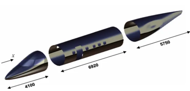
A midlight category executive aircraft, illustrated in Fig. 6, is utilized as the main application of this work. The aircraft presents a circular fuselage cross section, with configurations for 7 to 9 passengers. Figure 7 shows the fuselage segments: front fuselage, central fuselage and rear fuse-lage. The central fuselage segment, with 6.92 m long and a diameter of 2.10 m, is conceptually designed with the present metamodeling approach.
Figure 6 Executive aircraft under analysis.
Figure 7 Fuselage segments
Latin American Journal of Solids and Structures 11(2014) 223 – 244
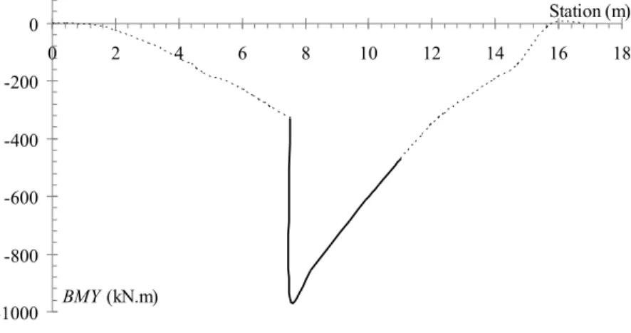
The ultimate load (1.5limit load) is applied, since the failure mode in the context of this work, instability by different criteria, is assumed as being the failure of the whole fuselage. Even-tual post-buckling behavior is disregarded. Figures 8 and 9 show the bending moment BMY and shear force SLZ, respectively, along the fuselage for the presented load case. The torsion moment is nil. The bolded curves refer to the part of the central fuselage under analysis. This region is limited by the connection of the central fuselage to the wing and by the connection to the rear fuselage, stations x = 7.52 m and x = 11.02 m, respectively.
-1000 -800 -600 -400 -200 0
0 2 4 6 8 10 12 14 16 18 Station (m)
BMY (kN.m)
Figure 8 Bending moment diagram.
-100 -50 0 50 100 150 200
0 2 4 6 8 10 12 14 16 18
Station (m)
SLZ (kN)
Figure 9 Shear force diagram.
3.3.1 A nalytical Solution
Latin American Journal of Solids and Structures 11(2014) 223 – 244
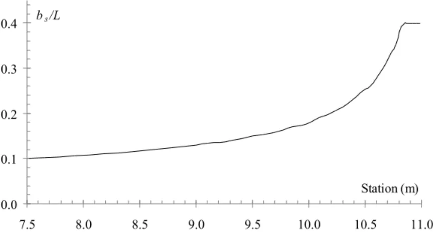
It can be seen that the parameter bs/L grows from the connection of the central fuselage to the wing up to its connection to the rear fuselage, as the load decreases. Since it is assumed that the spacing between the stringers bs in each bay is kept constant and the number of stringers does not change along the fuselage, the spacing between frames L reduces from the connection to the wing up to the rear fuselage. The spacing between stringers for the optimal design, which is con-stant around the cross section and along the fuselage, equals to bs = 13.74 mm.
0.0 0.1 0.2 0.3 0.4
7.5 8.0 8.5 9.0 9.5 10.0 10.5 11.0 Station (m)
bs/L
Figure 10 bs/L distribution along the fuselage span.
Figure 11 shows the skin thickness ts distribution along the fuselage span. The skin thickness is defined by the relation ts/bs, which varies itself with the input parameter bs/L. It also can be noted that the skin thickness variation along the fuselage span, 0.44 < ts < 0.45 mm, is almost negligible.
0.438 0.440 0.442 0.444 0.446 0.448 0.450 0.452
7.5 8.0 8.5 9.0 9.5 10.0 10.5 11.0 Station (m)
ts (mm)
Latin American Journal of Solids and Structures 11(2014) 223 – 244
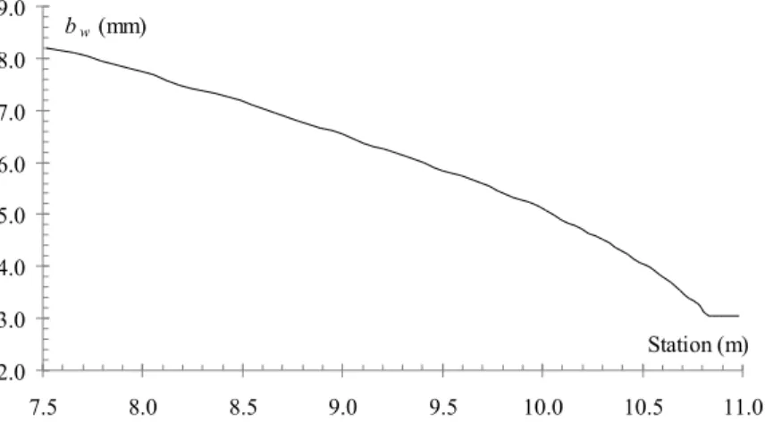
Figure 12 shows the distribution of skin, stringer and frame thicknesses, ts, tw, tf, respectively, along the fuselage span, while the stringer height bw distribution is shown in Fig. 13. It is noticed that the thickness and the height of the stringers decreases from the connection of the central fuselage to the wing up to the rear fuselage, following the reduction of the acting loads.
thickness (mm)
0.2 0.3 0.4 0.5 0.6 0.7 0.8 0.9
7.5 8.0 8.5 9.0 9.5 10.0 10.5 11.0 Station (m)
tf tw
ts
Figure 12 Stringer and frame thicknesses distribution along the fuselage span.
2.0 3.0 4.0 5.0 6.0 7.0 8.0 9.0
7.5 8.0 8.5 9.0 9.5 10.0 10.5 11.0
Station (m) bw (mm)
Figure 13 Stringer height distribution along the fuselage span.
It was decided that the frames should have the same height as the stringers of a certain bay, due to the innovative resulting geometry. So, Fig. 13 also presents the frame height distribution along the fuselage span. The resulting geometry alludes to a reticulated pattern of the structure. It is an option and trend that can lead to the manufacture of new aerospace structures. Although, the dimensions and spacing of the structural elements found herein make the fuselage manufacturing unfeasible considering current processes in the aeronautical industry nowadays.
Latin American Journal of Solids and Structures 11(2014) 223 – 244
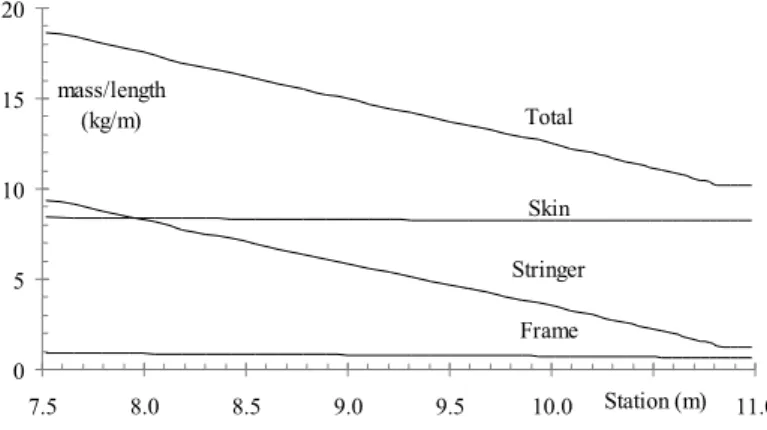
total mass distribution of the structure is mostly due to the stringer mass variation. The bs/L increase along the fuselage span, observed in Fig. 10, presents strong connection with the reduc-tion of the stringer mass by the panel length, as well as with the almost invariable behavior of the frame mass by the panel length. Table 3 shows the final distribution of structural mass in the fuselage segment.
Total
Skin
Stringer
Frame
0 5 10 15 20
7.5 8.0 8.5 9.0 9.5 10.0 Station (m)10.5 11.0
mass/length (kg/m)
Figure 14 Distribution of the ratio to the structural mass by panel length.
Table 3 Structural mass distribution in the fuselage segment under analysis.
Component Mass (kg) % of the total mass
Stringers 18.6 37%
Frames 2.8 5%
Skin 29.1 58%
Total 50.4 100%
3.3.2 Finite elem ent analysis
A global finite element model of the resulting fuselage designed in the previous item is built for linear static analysis in Nastran. Two load cases are applied: pressurization (for tensile verifica-tion) and pull-up maneuver loads (for pre-sizing analytical validaverifica-tion). Shell elements CQUAD4 were used to represent the fuselage skin and bar elements CBAR to represent the fuselage string-ers and frames. Figure 15 shows a detail of the finite element mesh of the fuselage structure.
Latin American Journal of Solids and Structures 11(2014) 223 – 244
Figure 15 Finite element mesh of some panels of the fuselage.
The ultimate pressurization load, in accordance to the 25.365 item of the Federal Aviation Regu-lations - Part 25 (2011), is equal to 2ΔP (0.14 MPa) and must be applied omitting other loads. Figure 16 presents the maximum combined stress distribution in the frames and Fig. 17 presents the Von Mises stress distribution in the reinforced panels.
Latin American Journal of Solids and Structures 11(2014) 223 – 244 Figure 17 Panel Von Mises stress for the pressurization case [×10MPa].
The maximum stress equals to 346 MPa in the frames and 349 MPa in the reinforced panels, which is below the material ultimate tensile stress (Ftu= 469 MPa), indicating that the fuselage structure withstands its ultimate pressurization load. This first numerical analysis demonstrates that, despite the fuselage has been designed based on a reinforced panels under compressive loads criterion, the resulting structure supports its most severe tensile requirement also.
Latin American Journal of Solids and Structures 11(2014) 223 – 244
Figure 18 Stress in the longitudinal x-direction – Global Model [×10MPa].
The compressive stresses of the lower reinforced panels are almost constant along the whole span of the central fuselage, varying from 270 MPa up to 300 MPa. This interval is in accordance with the compressive allowable stresses to the reinforced panels metamodel, Tab 1. Therefore, this finite element analysis demonstrates that the analytical procedure is consistent and valid. The compressive stresses throughout the lower fuselage are around 2/3 of the compressive yield stress, which implies that the structure is globally optimized, avoiding local instability failures at stress-es far below the material yield comprstress-essive limit.
Latin American Journal of Solids and Structures 11(2014) 223 – 244 Figure 19 Stress in the longitudinal x-direction – Local Model [×10MPa].
Despite the presence of certain singularities observed in the intersections of frames with stringers at the ends of the detailed local model due to the boundary conditions and applied loads, the compressive stress level remains similar to that obtained in the global model, between 270 MPa and 300 MPa.
The six first buckling modes and their respective eigenvalues
λ
, representing the ratio of thebuckling load by the acting load, are presented in Fig. 20. The first two buckling modes occurred in a region where high concentrated stresses can be observed in Fig. 19, due to non-physical be-havior caused by the transfer of the global displacements and loads to the detailed local model. Thus, they represent spurious modes and are disregarded. The buckling loads to the first modes are very close, indicating that the collapse of the structure occurs when its critical load is reached without an extra margin for post-buckling effects.
Latin American Journal of Solids and Structures 11(2014) 223 – 244
Figure 20 Failure modes – Local Model.
It is also evident that the compressive strength of the structure is at least 21.4% higher than the fuselage acting loads, resulting in margins of safety greater than those obtained by the analyt-ical method. This difference may be explained by some conservative hypotheses adopted during the pre-sizing of the fuselage:
- the presented methodology is conservative when it assumes that the skin is sized as a
simply supported plate and the stringers as simply supported flanges;
- the analytical methodology is developed for flat panels, while the fuselage possesses
Latin American Journal of Solids and Structures 11(2014) 223 – 244
- buckling FE simulation to the flat reinforced panels demonstrated a compressive strength
3.6% greater than analytical predicted, Fig. 4.
Throughout this specific application, some simplifications and hypotheses have been adopted. Thus, opportunities are identified for future investigation to this new fuselage concept:
- a dedicated procedure for dimensioning the fuselage ceiling reinforced panels, subjected to
tensile stresses, mainly governed by fatigue and damage tolerance criteria;
- a study of local reinforcements for fuselage openings, in order to accommodate windows
and doors.
4 C O N C LU SIO N
An efficient metamodel for reinforced panels under compressive loads, typically used in light-weight aircraft structures, has been proposed. The metamodel represents a replicable cell of wing box or fuselage composed of integrally machined panels. The presented analytical formulation for the conception of reinforced panels under compressive loads is based on the synthesis of four sta-bility criteria: section crippling, web buckling, flange buckling and column collapse. The alumi-num alloy AL7050-7451 Plate 2.75in, a typical choice in modern aircraft industry, is selected to the reinforced panel metamodel. The structure is expected to work in the linear elastic domain.
The local buckling of the skins is usually allowed and the sizing of the stringers and frames is performed taking into account the post buckling behavior of the panels. In the methodology adopted herein, the buckling modes occur simultaneously, causing the collapse of the whole struc-ture, so the structure can not buckle at all.
The numerical applications show that the geometry of the basic structural components of a fuselage can be easily and quickly determined by means of the presented methodology. The con-sistency and validity of the methodology is demonstrated by finite element analyses.
The design of a 9-passenger aircraft fuselage yields to an innovative structure from those usu-ally adopted in the aeronautical industry. The resulting geometry alludes to a reticulated pattern of the structure. It is an option and a trend that can lead to new aerospace structures. Although, the small dimensions and spacing of the structural elements found herein make the fuselage man-ufacturing unfeasible considering current processes in the aeronautical industry nowadays. It is expected that the presented formulation could be more helpful to the pre-sizing of structures sub-jected to higher compressive loads, such as in the case of the upper skin panels of a wing box.
References
Abaqus (2006). User’s Manual.
Alinia, M.M., Habashi, H.R., Khorram, A. (2009). Nonlinearity in the postbuckling behaviour of thin steel shear panels. Thin-Walled Structures 47, 412–420.
Bedair, O.K. (1997). The Elastic Behaviour of multi-stiffened plates under uniform compression. Thin-Walled Structures, 27-4, 311-335.
Bruhn, E.F. (1973). Analysis and design of flight vehicle structures. Purdue: Jacobs Pub.
Latin American Journal of Solids and Structures 11(2014) 223 – 244
Caseiro, J.F., Valente, R.A.F., Andrade-Campos, A., Yoon, J.W. (2011). Elasto-plastic buckling of integrally stiffened panels (ISP): An optimization approach for the design of cross-section profile. Thin-Walled Struc-tures, 49, 864–873.
Federal Aviation Regulations – Part 25 (2011). Airworthiness Standards – Transport Category Airplanes – Subpart C – Structures. Federal Aviation Administration.
Forrester, A.I.J. , Sóbester, A. , Keane, A.J. (2008). Engineering design via Surrogate Modelling: A practical Guide. Progress in Astronautics and Aeronautics, vol. 226, John Wiley and Sons.
Gerard, G. (1958). The Crippling Strength of Compression Elements. Jour. Aeronaut. Science, v 25 (1), 37-52. http://www.engineering.leeds.ac.uk/documents/InauguralLecture_VT_short.ppt.
Kolakowski, Z. and Teter, A. (2000). Interactive buckling of thin-walled beam-columns with intermediate stiff-eners or/and variable thickness. International Journal of Solids and Structures 37, 3323-3344.
Lee, J. and Kang, S. (2007). GA based meta-modeling of BPN architecture for constrained approximate opti-mization. International Journal of Solids and Structures 44, 5980-5993.
Lundquist, E. and Stowell, E. (1941). Critical Compressive Stress for Outstanding Flanges. Report No. 734. Langley Memorial Aeronautical Laboratory, National Advisory Committee for Aeronautics. Langley Field, VA.
Lynch, C., Murphy, A., Price, M., Gibson, A. (2004). The computational post buckling analysis of fuselage stiffened panels loaded in compression, Thin-Walled Structures, 42 , 1445-1464.
MSC.Nastran, (2004). MSC.Software, Reference Manual.
Smith, J., Hodgins, J., Oppenheim, I., Witkin, A. (2013). Creating Models of Truss Structures with
Optimiza-tion, Carnegie Mellon University and Pixar Animation Studios,
http://www.smokingrobot.com/pdfs/SIG02_structures.pdf.
Stamatelos, D.G., Labeas, G.N., Tserpe, K.I. (2011). Analytical calculation of local buckling and post-buckling behavior of isotropic and orthotropic stiffened panels. Thin-Walled Structures 49, 422–430.
Timoshenko, S. and Gere, J. (1961). Theory of Elastic Stability. McGraw-Hill.
Toropov, V. (2013). Optimization: getting more and better for less, inaugural lecture, aerospace and structural engineering, University of Leeds,
Wang, Q. (1997). Lateral buckling of thin-walled open members with shear lag using optimization techniques. International Journal of Solids and Structures, 34-11, 1343-1352.
![Figure 3 Compressive stress contour [ × 10MPa].](https://thumb-eu.123doks.com/thumbv2/123dok_br/18885452.423731/8.892.238.700.655.930/figure-compressive-stress-contour-mpa.webp)