*e-mail: [email protected], [email protected], [email protected], [email protected]
Analysis of the Relative Rib Area of Reinforcing Bars Pull Out Tests
Maria Teresa Gomes Barbosa*, Emil de Souza Sánchez Filho*,
Thais Mayra de Oliveira*, White José dos Santos*
Departamento de Construção Civil, Faculdade de Engenharia, Campus Universitário,
Universidade Federal de Juiz de Fora – UFJF,
Bairro Martelos, 36010-150 Juiz de Fora - MG, Brazil
Received: June 23, 2008; Revised: December 11, 2008
The good performance of reinforced concrete structures is ensured by the transfer of stress linking a reinforcing bar and the surrounding concrete. The bond steel-concrete is a very complex phenomenon. This paper presents the experimental results of a program with specimens used in the pull out test with concrete strength of 20, 40, 60, 80 and 100 MPa and four different steel diameters: 12.5, 16.0, 20.0 and 25.0 mm. The test results indicated that the bond stress varied with the bars rib face angle, rib spacing, and rib height. The trends of the results were independent of the concrete strength with the test results, and design recommendations made as regards optimum rib geometries of deformed bars with high bond-slip characteristics.
Keywords: bond stress, pull out test, reinforcing steel, rib geometries
1. Introduction
The behavior of the bond between the steel reinforcement and the concrete enveloping the bar is of fundamental importance in re-lation to the load capacity of the structural concrete. Knowledge of this is imperative to ascertaining anchorage lengths, the lap splices, tension stiffening between cracks and other important factors for the structures1,2,3,9.
The concrete strength is the main parameter that influences the anchorage length and the transmission of tensions concentrated on the bars ribs. Other factors that influence the bond stress are the roughness and/or irregularities on the bar surface; the diameter of the bars; type and positioning of the ribs.
1.1. Factors that influence the bond
The main factors that influence the steel-concrete bond1: •Strength of the concrete: The analyses of fly ash conducted
by most authors indicate that its presence increases the strength and the bond of the concrete. The increase of the strength of the bond is attributed to the compacted concrete and the reduced thickness of the transition zone between the concrete and the reinforced concrete.
•Diameter of the bars: An increased diameter of the
reinforce-ment reduces the maximum bond stress. Such fact is explained by the thickness of the transition zone, thicker on the bars of larger diameter. The diameter, along with larger dimensions of the ribs holds more water under the bar providing a thicker transition zone, making it more porous and facilitating the crushing for rib compression. This variable is considered less important since the thickness and the anchorage length are multiples of the bar diameter11,12.
•Loading Age: The loading age influences the bond in the same way as the mechanical strength of the concrete4.
•The Production of the Concrete: The production influences
the bond in the same way as the strength of concrete. This paper presents the results of pull out tests of different con-crete strengths: 20, 40, 60, 80 and 100 MPa and four different steel diameters: 12.5, 16.0, 20.0 and 25.0 mm and design recommendations were made concerning optimum rib geometries of deformed bars with high bond-slip characteristics.
2. Studying the Bond
The bond is the connection between the reinforcement and the concrete which prevents slipping between these two materials. Therefore, the materials are deformed together resulting in the effort being transferred from one to the other, that is to say, whenever the stress in the bar varies, be it due to compression or due to traction, and supposing the bond stress is developed throughout the bar, there will be a transfer of effort between the bar and the concrete.
For smooth bars, where rupture from slipping occurs, the bond is mainly consists of chemical adhesion between the cement paste and the bar; when that connection is broken, strength appears in the slipping due to friction, the intensity of which depends on the surface type of the bar. In these kinds of bars, a mechanical bond can appear between the concrete and the steel due to the irregularities on the surface. Therefore, the force capable to break the bond is proportional to the area of the bar in contact with the concrete where the adhesion occurs; friction and surface type are verified.
In the case of other bars (rib bars) the strength in the slipping is due, mainly, to the strength that the concrete offers to the pressures exercised on it by the ribs, that means, to the mechanical action between the concrete and the ribs. The effect of the chemical adhe-sion, in this case, is minor and the friction does not occur until the reinforced steel is displaced.
When traction efforts are applied to reinforced steel, traction and compression efforts are produced in the concrete that become a main stress of traction and of compression, respectively. Therefore, the maximum value of the bond stress is limited by the smallest value of the main stress (traction or compression). When one of those stresses is exceeded in the concrete due to the application of a traction effort in the reinforcement, this ruptures the mechanical bond.
loaded to the point of rupture, longitudinal fissures appears. However, these can begin as longitudinal fissures invisible on the surface of the concrete before the maximum capacity of load is reached. As a longitudinal fissure appears, they increase the displacement between the bar and the concrete and the bond stress is transferred along the anchorage length to where the fissures appear. The radial components of the strength of the bond impose a load and when they are loaded to maximum capacity, they break suddenly14.
The bond can be described ideally as a shearing stress between the surface of the reinforcement and the concrete that surrounds it. That mechanism is determined by means of the relative displacement between the reinforcement and the concrete.
3. Experimental Investigation
The study of the bond is presented by the relationship between the bond stress and the slipping of the reinforcement. The former is identified by the shearing stress in the intercession reinforced-concrete and, the latter, by the relative displacement between the reinforce-ment and the concrete.
The experimental program with specimens used in the pull out tests with concrete strengths: 20, 40, 60, 80 and 100 MPa and four dif-ferent steel diameters: 12.5, 16.0, 20.0 and 25.0 mm2,3 were made.
The pull out test is the most traditional bond test and it consists of the extraction of a bar, usually positioned in the center of a specimen test cubic of concrete. This method enables calculation, according to RILEM (CEB (1983)), of the values of the medium and maximum bond stress for each bar diameter used in the different strength con-cretes, so as to compare them with the values of given standards, as well as to trace curves representing the characteristics of bond stress x slipping.
3.1. Materials
Concrete: The chemical and physical analyses of the cement are listed in Table 1. River sand and gneiss gravel aggregate are used. The fineness modulus of aggregate is 2.52 (for river) and 5.75 (for gneiss); and the maximum diameters are 2.4 and 9.5 mm, respectively. The superplatifized are used RX 4000 REAX. Table 2 shows the mixture proportions of concrete (cement: sand aggregate: gravel aggregate: water/cement factor) are used in order to obtain an approximate compressive concrete strength at 28 days of 20, 40, 60, 80 and 100 MPa. The concrete specimens undergo the pull out test at the age of 90 days.
Steel bars: Table 3 and Table 4 show the characterization of reinforcing steel for all steel bar diameters. The relative rib area re-inforcing bars are prescribed in CEB5,6,7 and EUROCODE8. If relative
rib area reinforcing bars (ƒR= 0.056)) attain the minimum prescribed value in the standardizations5,8, the steel bars are considered to be
of high bond stress.
3.2. Items of investigation
Tests were conducted on concrete of four different reinforcement diameters and five different concrete strengths according to the pull
out test5. As many as eight specimens are made for each diameter and
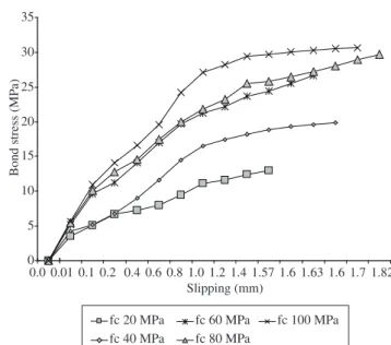
concrete strength. At the age of 90 days, concrete specimens are tested and medium bond stress, rupture bond stress and maximum slipping are obtained, as illustrated in Table 5 and Figures 2 to 5.
4. Experimental Results and Discussion
The ribs angle of reinforcement bars proposes6,7 between 55° and
65° but several authors give the value 55°. For Brazilian steels with nominal diameters 12.5, 16.0, 20.0 and 25.0 mm, this angle is 46°, 46°, 45° and 50°, respectively. The angle of the 25.0 mm bar is bet-ter than when one considers the rib spacing and rib height for such high strength concrete.
In order to obtain an equation that represents the results for rela-tive rib area reinforcing in function of the rib angle, the rib spacing and of the rib height for the higher bond stress a regression was used. Equation 1 represents the analysis.
Equation 1: Relative Rib Area Reinforcing Bars
0.0274 0.0049 0.0024 0.0028 0.0091
R R R
f = − − f + β + h − S (1)
(Error = 0.0, R² = 1.0)
The data of Table 5 shows:
• Ifthestrengthofconcreteincreases,thebondstressincreases
because there is a decrease in the porosity to transition zone between aggregate/paste - reinforcement/paste;
Table 1. Physical and chemical compositions of Portland cement – type V.
Properties CPV
Specific gravity (mm) 4.6
Fineness modulus 4.59
CaO/ SiO2 2.67
CaO (%) 60.56
SiO2 (%) 22.68
MgO (%) 1.94
Al2O3 (%) 6.53
SO3 (%) 0.14
K2O (%) 0.73
Fe2O3 (%) 2.58
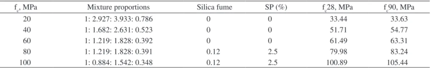
Table 2. Concrete mixture proportions and the strength of concrete.
fc, MPa Mixture proportions Silica fume SP (%) fc28, MPa fc90, MPa
20 1: 2.927: 3.933: 0.786 0 0 33.44 33.63
40 1: 1.682: 2.631: 0.523 0 0 51.71 54.77
60 1: 1.219: 1.828: 0.392 0 0 61.49 63.31
80 1: 1.219: 1.828: 0.391 0.12 2.5 79.98 83.24
100 1: 0.884: 1.542: 0.348 0.12 2.5 100.89 105.44
• Slippinghadbeenastronginluenceofstrengthofconcrete10,13
and if the diameter of steel bar increases, the slipping increases, see Figure 6.
In order to obtain an equation that represents the results for me-dium and maximum bond stress in function of the concrete strength and of the diameter of the bar, for Brazilians materials, a regression was used resulting in Equations (2) to (5).
Strength of concrete ≤ 50 MPa (7.25 ksi):
0.006 0.086
0.663 fc
M e fe
τ = (Error = 1.1 MPa; R² = 0.9317) (2)
0.029 0.115
0.774 fc
R e fe
τ = (Error = 1.1 MPa; R² = 0.9820) (3)
Strength of concrete > 50 MPa (7.25 ksi):
0.059 0.005
3.377 fc
M e f
τ = (Error = 1.1 MPa; R² = 0.9492) (4)
0.114 0.006
2.519 fc
R e f
τ = (Error = 1.1 MPa; R² = 0.9653) (5)
5. Conclusions
Based on the analysis of the test results of pull out specimens, it is concluded that:
• If the strength of concrete increases, bond stress increases
because there are reductions in the transition zone with the silica fume addition;
• Slipping was proportionally relative to the strength of the concrete and the bar diameter, i.e., when concrete strength and bar diameter increase the slipping increases;
Table 3. Characterization of steel bars.
f (mm) fy,MPa fyd,MPa
12.5 565.3 782.5
16.0 626.9 744.8
20.0 529.0 841.8
25.0 618.6 721.6
Table 4. Characterization of steel bars (rib’s bar).
f (mm) β (°) hR, cm (% f) SR, mm (% f) fR calculated fR minimum
12.5 46 0.12 (9.0%f) 0.84 (70%f) 0.071 0.056
16.0 46 0.16 (9.0%f) 0.92 (62%f) 0.082 0.056
20.0 45 0.18 (9.0%f) 0.17 (64%f) 0.077 0.056
25.0 50 0.25 (9.0%f) 1.57 (70%f) 0.079 0.056
Table 5. Medium bond stress, rupture bond stress (MPa) and maximum slipping (mm) in the pull out test.
fc (MPa) Diameter of bar, mm
12.5 16.0 20.0 25.0
τM τR S τM τR S τM τR S τM τR S
20 4.03 6.98 1.35 6.59 12.9 1.57 7.17 16.8 2.10 13.2 32.0 2.21
40 7.27 13.0 1.38 8.65 19.9 1.66 12.7 36.7 2.12 18.6 52.5 2.32
60 8.56 13.9 1.30 12.0 26.6 1.63 15.5 40.0 1.55 19.6 x 2.00
80 10.0 16.7 1.31 12.5 29.7 1.82 17.6 46.0 1.80 19.9 x 2.01
100 10.8 17.4 0.94 14.6 30.6 1.70 19.4 48.5 1.70 21.5 x 2.20
x – Not rupture with 60 MPa is the maximum capacity of equipment.
0 2 4 6 8 10 12 14 16 18
0.00 0.01 0.10 0.20 0.40 0.60 0.80 0.94 1.00 1.20 1.30 1.31 1.35 1.38 Slipping (mm)
Bond stress (MP
a)
fc 20 MPa fc 40 MPa
fc 60 MPa fc 80 MPa
fc 100 MPa
Figure 2. Bond Stress vs. Slipping (f= 12.5 mm).
fc 20 MPa fc 40 MPa
fc 60 MPa fc 80 MPa
fc 100 MPa 0
5 10 15 20 25 30 35
0.0 0.01 0.1 0.2 0.4 0.6 0.8 1.0 1.2 1.4 1.57 1.6 1.63 1.6 1.7 1.82 Slipping (mm)
Bond stress (MP
a)
• Thebarwitharibangleof47°developedthegreatestbond
stress for Brazilian materials. The others authors obtained 55°;
• The bar with a rib spacing of 70%f and a rib height equal to 9%f developed greater bond stress, according the results obtained in this research;
• Equation(1)identiiedgoodresultsforbondstress,especially
for high strength concrete. It’s possible to substitute the terms prescribed in the international and Brazilian standard;
• Ifthediametersofthebarsandstrengthoftheconcreteincrease,
the bond stress increases. In this case, concrete vibration is the most important factor. Many authors’11,12 state the opposite
because their research was concerned with the transition zone between aggregate/paste – reinforcement/paste. The high per-formance concrete tends to entrap large air pockets and bubbles that must be eliminated by internal or external vibration;
• Theequationformediumbondstressandmaximumbondstress
are proposed in virtue of the bar diameter and the concrete strength for Brazilian materials.
Acknowledgements
The authors would like to thank the Brazilian HOLCIM for their financial assistance during the construction and testing of the specimens.
References
1. Barbosa MTG. Evolution of the Behavior of the Bond in High Strength Concrete. In: III International Conference on high-Performance Concrete, Performance and Quality Concrete Structure; 2002. Recife, Pernambuco: American Concrete Institute; 2002.
2. Barbosa MTG, Sanchez E. Analysis of the Bond Behavior of Brazilian Steel by Theory of Plasticity. In: XXXII Jornadas Sulamericanas de Engenharia Estructural; 2006. Campinas: UNICAMP; 2002.
3. Barbosa MTG. The Bond Stress in Brazilian Standard. In: International Conference held at the University of Dundee, Scotland, UK; 2005.
Dundee: Thomas Telford Publishing; 2005.
4. Chapmam R, Shah S. Early-age Bond Strength in Reinforced Concrete. ACI Materials Journal 1987; 84(6): 501-510.
5. COMITÉ EURO-INTERNATIONAL DU BÉTON: RILEM/ CEB/ FIP.
Concrete Reinforcement Technology. Paris: George Publishing Company; 1983.
6. COMITÉ EURO-INTERNATIONAL DU BÉTON. Structural Concrete.
Paris; 1999. Bulletin n. 1.
7. COMITÉ EURO-INTERNATIONAL DU BÉTON. Structural Concrete.
Paris; 1999. Bulletin n. 2.
8. EUROCODE 2. Stahlbeton – und Spannbeton. London: Springer Verlag; 1993.
9. Ferguson PM. Bond Stress – the State of Art. Journal of the American Concrete Institute 1966; 63(1): 1161-1190.
10. Mirza SM, Houde J. Study bond stress-slip relationship in reinforced concrete. Journal of the ACI 1979; 76(1): 19-46.
11. Reynolds GC, Beddy A. Bond Strength of Deformed Bars. In:
International Conference on Bond and Concrete; 1982. London: P. Bartoz; 1982. p. 434-445.
Figure 6. Maximum slipping vs. strength of concrete. fc 20 MPa
fc 40 MPa
fc 60 MPa fc 80 MPa
fc 100 MPa 0
5 10 15 20 25 30 35 40 45 50
0.0 0.01 0.1 0.2 0.4 0.6 0.8 1.0 1.2 1.4 1.55 1.6 1.7 1.8 2.0 2.1 2.12 Slipping (mm)
B
on
d
st
re
ss
(
M
P
a)
Figure 4. Bond Stress vs. Slipping (f = 20.0 mm).
fc 20 MPa fc 40 MPa
fc 60 MPa fc 80 MPa
fc 100 MPa 0
10 20 30 40 50 60 70
0.0 0.01 0.1 0.2 0.4 0.6 0.8 1.0 1.2 1.4 1.6 1.8 2.0 2.01 2.2 2.21 2.32 Slipping (mm)
B
on
d
st
re
ss
(
M
P
a)
Figure 5. Bond Stress vs. Slipping (f = 25.0 mm).
0.0 0.5 1.0 1.5 2.0 2.5
20 40 60 80 100
fc (MPa)
M
ax
im
um
sl
ip
pi
ng
(
m
m
)
12. Sorooushian P, Choi K. Local Bond of Deformed Bars with different Diameters in Confined Concrete. ACI Structural Journal 1989; 86(2):
217-222.
13. Soroushian P, Choi K, Park G, Aslani F. Bond of deformed bars to concrete: effects to confinement and strength of concrete. ACI Materials Journa
1991; 88(3): 227-232.
14. Tassios T. Properties of Bond Between Concrete and Steel under Load Cycles Idealizing Seismic Actions. In: CEB – Symposium, Rome; 1979. Pure and Applied Chemistry; 1979. (bulletin d’information n. 131). 15. Tepfers R. Cracking of Concrete Cover Along Anchored Deformed
Reinforced Bars. Magazine of Concrete Research 1979; (106): 3-12.
Nomenclature
CPV = Portland cement type V (Brazilian standard); f = diameter steel bar;
ƒR = relative rib area;
ƒc = compressive strength of concrete;
ƒc28 = compressive strength of concrete at 28 days of age; ƒc90 = compressive strength of concrete at 90 days of age;
hR = rib height;
SR= rib spacing;
S = maximum slipping; SP = superplastized; β = rib face angle;