SYNTHESIS OF SUPERVISORS FOR TIME-VARYING DISCRETE EVENT
SYSTEMS
Eduard Montgomery Meira Costa
∗ [email protected]Antonio Marcus Nogueira Lima
† [email protected]∗Departamento de Engenharia El´etrica, Universidade Federal da Bahia 40210-630 Salvador, BA, Brasil
†Departamento de Engenharia El´etrica, Universidade Federal de Campina Grande 58109-970 Campina Grande, PB, Brasil
ABSTRACT
We introduce a time-varying automaton to model discrete event systems. The structure of this time-varying automaton is very similar structure to (max,+) automaton, but allowing variable event lifetimes. Based on this time-varying automa-ton the design of timed supervisors is obtained by using the dioid algebra, where the languages used to describe the dis-crete event system as well the desired specification are re-placed by matrices defined in such algebra and the supervisor synthesis is achieved through simple matrix operations. The proposed synthesis algorithm allows one to synthesize super-visors for un-timed DES, timed DES with constant event life-time and life-timed DES with variable event lifelife-time. All these cases are treated with the same basic algorithm, the differ-ences rely only on the definition of the event lifetime func-tions. The proposed algorithm presents a complexity order equal to the supervisor synthesis algorithm of un-timed dis-crete event systems. The proposed approach can be consid-ered as an alternative procedure, based on a non-traditional algebraic structure, to achieve the supervisor synthesis for discrete event systems.
KEYWORDS: Time-Varying Automata, discrete event sys-tems, supervisory control.
Artigo submetido em 24/04/2002
1a. Revis ˜ao em 31/07/2002; 2a. Revis ˜ao em 20/11/2003 3a. Revis ˜ao em 6/04/2004
Aceito sob recomendac¸ ˜ao do Ed. Assoc. Prof. Takashi Yoneyama
RESUMO
O autˆomato com temporizac¸˜ao vari´avel ´e introduzido nesse artigo para modelar sistemas a eventos discretos. A estrutura desse autˆomato ´e bastante similar `a estrutura do aut ˆomato (max,+), mas apresentando tempos de vida vari´aveis. Base-ado nesse autˆomato o projeto de supervisores temporizBase-ados ´e obtido por meio da ´algebra de di´oides, onde as linguagens utilizadas para descrever o sistema a eventos discretos, bem como a especificac¸˜ao de comportamento desejada s˜ao defini-das por matrizes descritas nesta ´algebra e a s´ıntese do super-visor ´e formalizada atrav´es de simples operac¸˜oes matriciais. O algoritmo de s´ıntese proposto permite sintetizar superviso-res para sistemas a eventos discretos n˜ao temporizados, sis-temas a eventos discretos temporizados com tempos de vida constantes e e vari´aveis. Todos esses casos s˜ao tratados com o mesmo algoritmo b´asico, em que a diferenc¸a existe apenas na definic¸˜ao das func¸ ˜oes de tempos de vida dos eventos. O algoritmo proposto apresenta uma ordem de complexidade igual ao algoritmo de s´ıntese do supervisor para sistemas a eventos discretos n˜ao temporizados. A formulac¸˜ao proposta pode ser considerada como um procedimento alternativo ba-seado numa estrutura alg´ebrica n˜ao tradicional, para cons-truir supervisores para sistemas a eventos discretos.
1
INTRODUCTION
Manufacturing systems, traffic systems, computer networks, communication protocols, process control plants are exam-ples of discrete event systems (DES). A DES is a dynamic system in which state changes occur in response to the oc-currence of events. The behavior of a DES can be expressed in terms of a languageLand the desired behavior is specif-ied by another languageE. In general,L⊆Emeaning that the DES may generate illegal behaviors. A supervisor is de-signed to eliminate the illegal behaviors. The set of events (Σ) is partitioned into controllable (Σc) and uncontrollable (Σuc) events thus creating the possibility for controlling the DES. Controllable events can be enabled or disabled by a supervisor which actively monitors the DES and can inter-vene at any moment to prevent an illegal behavior. The su-pervisor control problem can be elegantly solved by using the Supervisory Control Theory (SCT) (Ramadge e ham, 1987b; Ramadge e Wonham, 1987a; Ramadge e Won-ham, 1982). Automata theory and formal languages theory form the basis of this theory. The supervisor as synthesized by the SCT deals only with the un-timed or logic behavior where there is no timing information explicitly associated to the events of the DES.
The timed behavior of DES is of great applied interest but also of significant complexity. Timed automata are one of the most studied models for representing real-time systems (Saksena e Selic, 1999). In some cases the timing infor-mation must be explicitly introduced to guarantee that the control action be feasible within the designated time bounds. Furthermore, these time bounds may be uncertain or time-varying and thus an adaptive supervisor must synthesized.
One approach to control a timed DES is to adopt a global clock and to introduce a clock-tick event (Brandin e Won-ham, 1994). The use of the ‘tick’ event, introduces new
classes of events (prospective, remote, forcible, prohibitible and eligible) and increases the complexity of the problem since the state space is augmented in order to represent the timing information related to each activity in the system. In this case there are two representations for the DES: i) for displaying the activity transition graph (ATG) (Ostroff e Wonham, 1990) is employed and ii) the timed transition graph (TTG) (Lawford, 1997) where the timing information is explicitly represented by using ‘tick’ transitions. The
de-sired behavior is given by a timed-language and the classical supervisor synthesis provided by the SCT is applied to the TTG.
The use of a max-algebra provides another alternative to deal with some control problems of timed DES (Cofer e Garg, 1996). In this case the DES is represented by a timed-event graph and the dynamics is modelled by a system of
lin-ear equations written in a nontraditional algebraic structure known as a dioid. The desired behavior is given by a range of acceptable execution times for the events and a supervi-sor synthesis algorithm was developed since the max-algebra model prevents the use of the classical algorithm provided by the SCT. It is important to remark that the synthesis of timed and un-timed supervisors is usually done by employing dif-ferent models for the DES.
This article proposes an unifying framework based on dioid algebra for synthesizing both timed and un-timed supervi-sors. It exploits the advantage of the dioid algebra for com-pactly representing the timing information and on the other hand allowing to express the DES model as well as the de-sired behavior in terms of languages. The proposed approach employs a time-varying automaton (TVA) to represent the DES by using its incidence matrix. The synthesis algorithm is based on the classical algorithm provided by the SCT and it is implemented in the matrix form.
This paper is organized as follows: in Section 2 some ba-sic definitions concerning dioid algebra, (max,+) automaton, formal series and languages are presented; in Section 3 the time-varying automaton is introduced; in Section 4 the su-pervisor synthesis is formulated; in Section 5 the susu-pervisor synthesis algorithm is presented; in Section 6 several illus-trating examples are studied and in Section 7 the conclusions of this work are presented.
2
PRELIMINARIES
Definition 1 A dioid is a setD endowed with two opera-tions: ⊕(addition) and⊗(multiplication), that satisfy the following axioms:
Axiom 1 Commutativity of⊕:
a⊕b=b⊕a,∀a, b∈D (1)
Axiom 2 Associativity of⊕:
(a⊕b)⊕c=a⊕(b⊕c),∀a, b, c∈D (2)
Axiom 3 Associativity of⊗:
(a⊗b)⊗c=a⊗(b⊗c),∀a, b, c∈D (3)
Axiom 4 Distributivity of⊗over⊕:
(a⊕b)⊗c= (a⊗c)⊕(b⊗c),∀a, b, c∈D (4)
c⊗(a⊕b) = (c⊗a)⊕(c⊗b),∀a, b, c∈D (5)
Axiom 5 Null element in⊕:
Axiom 6 Absorbing element in⊗:
a⊗ǫ=ǫ⊗a=ǫ,∀a∈D (7)
Axiom 7 Identity element in⊗:
∃e∈D:∀a∈D, a⊗e=e⊗a=e (8)
Axiom 8 Idempotency in⊕:
a⊕a=a,∀a∈D (9)
A dioid is said commutative if⊗is commutative.
Considering thatD=Rmax:=R∪ −∞, the null element is
ǫ:=−∞and the identity element ise:= 0. The⊕operator is the usualmaxand the⊗is the usual sum. In this caseDis commutative and the related algebra is known as the (max,+) algebra.
2.1
(max,+) automaton
The (max,+) automaton can be used to model the timed be-havior of DES. In this case the system dynamics can be de-scribed through formal series as explained in the following and it is also possible to consider the partition of the set of events (Σ) into controllable (Σc) and uncontrollable (Σuc) events, i.e.,Σ = Σc∪Σuc, as usual in the SCT.
Definition 2 A finite (max,+) automaton over an alphabetΣ
is a quadrupleA(max,+) = (Q, θ, T, φ)whereQis a finite
set of states,θ,φ,Tare mapsθ:Q→Rmax,φ:Q→Rmax
T :Q×Σ×Q→Rmax(named initial delays, final delays,
and transition times, respectively).
For displaying purposes a (max,+) automaton is represented by valued multigraph where the set of vertices is given byQ and there are three types of arcs:
i) The internal arcsi→σ j,∀i, j∈Q,σ∈Σ. IfTi,σ,j 6=ǫ the arci→jis valued by the scalarTi,σ,jlikei
Ti,σ,jσ → j;
ii) The input arcs→i,∀i∈Q. Ifθi6=ǫthe input arc is valued
by the scalarθilike→θi i;
iii) The output arcsi →,∀i ∈ Q. Ifφi 6= ǫthe output arc is
valued by the scalarφilikei φi →.
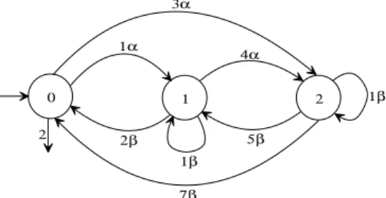
Example 1 LetΣ ={α, β}. The automaton with set the of statesQ={0,1,2}, transition timesT0,α,1= 1,T0,α,2= 3,
T1,α,2 = 4,T2,β,2= 1,T2,β,1 = 5,T2,β,0 = 7,T1,β,1 = 1,
T1,β,0 = 2, final and initial delays φ0 = 2 andθ0 = 0,
respectively (all the other values ofφ,θandTare equal toǫ) is shown in Figure 1. The values equal to0are omitted from the diagram, i.e., the not valued arc→0stands forθ0= 0.
Comparing a (max,+) automaton with an un-timed automa-ton having the same structure we can note that the transition function is embedded in theT map. The initial state is def-ined at the vertexq0 ∈Qin whichθq0 6=ǫand the marked states are those verticesqm ∈ Qwhereφqm 6=ǫ. The
dy-namics of a (max,+) automaton can be explained as follows:
1. There is a global clock that is continuously being incre-mented;
2. The arcs are valued byTi,σ,j ∈T,i, j∈Q. This means that the transition fromitoj takes at leastTi,σ,j units of time, or, in other words, given that the automaton reached statei, then it will jump to statejafter the oc-currence ofσ, however the event σwill be enabled to occur only afterTi,σ,junits of time. The termTi,σ,j is denoted the lifetime of the eventσ.
3. The initial stateq0 ∈Qwill be reached only afterθq0 units of time with respect to the global clock time origin;
4. When the automaton reaches a given stateithe coun-ters associated to events such that Ti,σ,j 6= ǫ will be initialized withTi,σ,j and all start decrementing simul-taneously. When a given counter reaches zero it stops decrementing and the respective event becomes enabled and may occur from now on;
5. When a given event occurs all the running counters are stopped and the state of the automaton changes;
6. When a marked state qm is reached it takes the final delay for the automaton to recognize the event sequence started atq0;
7. If at a given stateithere are two arcs leaving that state and the labels are equal but valued with different life-times then the automaton is said non-deterministic.
Example 2 The dynamics of the (max,+) automaton shown in Figure 2 can be described in the following way: i) After started the global clock att = 0it takes2units of time to reach the initial state1. ii) At t = 3the automaton may recognize the string3ε, whereεis the empty string. iii) At
0 1 2
2
7β 3α
1α
2β 1β
4α
5β
1β
t = 4 the counter of eventαreaches zero and it becomes enabled until its occurrence. iv) If αoccurs at state 1 the automaton will jump to state2. v) Once at state2it takes3
units of time for eventβto become enabled. vi) Ifβ occurs at state2the automaton will jump to state1. vii) Once again in state1it takes one more unit of time for the automaton to recognize the string8αβ. viii) Ifβ did not occurred at state
2then after one more unit of timeκbecomes enabled. Then, aftert = 8the eventsβandκare both enabled until one of them occurs. ix) Ifκoccurs at state2, the state3is reached. x) At state3it takes2units of time forβto become enabled. xi) Whenβoccurs the automaton returns to state1and then, after one unit of time it recognizes the string11ακβ.
In a (max,+) automaton a sequence of states is defined as a path. A path of lengthnis given by
p= (q0, ..., qn)∈Qn (10)
where
Qn :={p|p= (q0,· · ·, qn)∧q0, ..., qn∈Q}. (11)
A strings=σ1...σnis recognized in a path if
W(p, s):=θ(q0)⊗Tq0,σ1,q1⊗· · ·⊗Tqn−1,σn,qn⊗φ(qn)6=ǫ (12)
whereW(p, s)is the path weight function. In other words, a string is recognized if it takes a finite time for its completion. The mul-tiplicity of a string is the maximum of the weights for all the paths where that string is recognized, namely
A(max,+)|s
:= max
p∈QnW(p, s) (13)
A dater is a mapy: Σ∗→R
maxand(y|s)is interpreted as the time for completing the sequence of events that composess. A (max,+) automaton recognizes a dater if
(y|s) = A(max,+)|s
(14)
Example 3 The strings = αβ is recognized by the automaton shown in Figure 2 since
P(p, s) =θ1+T1,α,2+T2,β,1+φ0= 56=ǫ (15) withp= (1,2,1).
2 1
2α
3β
4κ 2β
1 2
3
Figure 2: Explaining the dynamics of a (max,+) automaton.
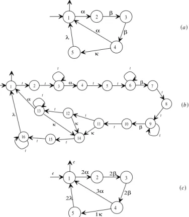
Example 4 The two automata shown in Figure 3(a) and (c) rec-ognize the same timed-languages. For the sake of comparison, the automaton given in Figure 3(a) is an ATG (Brandin e Won-ham, 1994) where the events are defined by (σq,q′, tσ,∞) ∈ Σ.
Then, in terms of Brandin and Wonham notation we have that the events (α1,2,2,∞), (β2,3,2,∞), (β3,4,2,∞), (α4,1,3,∞), (κ4,5,1,∞), (λ5,1,2,∞)are all of remote type. The automaton shown in Figure 3(b) is a TTG representing the dynamics of the ATG. Figure 3(c) shows a (max,+) automaton that exhibits the same dynamics. In the TTG, each arc labelled with at(‘tick’) indicates one unit of time. It is worth noting that the number of states of the (max,+) automaton is largely inferior to the number of states of the TTG. Besides, the timing information is more compact and directly represented with the (max,+) automaton.
1 2 3 4 5 6 7
8
9 10 11
12 13
14 15
16
t t t t
t
t
t t
t
t t
α β
β κ
λ α
1 2 3
4 5
e
e
3α 2λ
2α 2β
2β
1κ
(c) (a)
t t
t t
t
κ κ
1 2 3
4 5
α λ
α β
β
κ
(b)
Figure 3: Automata comparison: (a) ATG, (b) TTG and (c) (max,+) Automaton.
2.2
(max,+) automaton and formal series
Formal series can be used to describe timed and un-timed languages (Berstel e Reutenauer, 1988; Klimann, 1999).
Definition 3 A formal seriesfover an alphabetΣwith coefficients inDis a map
f: Σ∗→D (16)
where each strings∈Σ∗has its imagef(s)∈Dthat is denoted
The set of all the formal series overf with coefficients inD is denotedDhhΣii. Givenf1: Σ∗→D,f2: Σ∗→Dand∀s∈Σ∗ the setDhhΣiiis endowed with the following operations
(f1⊕f2|s) = (f1|s)⊕(f2|s) (17)
(f1⊗f2|s) =
M
uv=s
(f1|u)⊗(f2|v). (18)
These operations are known as the Cauchy sum and product, re-spectively. The Cauchy sum represents the union of languages and the Cauchy product represents the concatenation. The convention
(f|s) =ǫindicates thatsnever occurs.
The star operation can also be defined for the formal series.
Definition 4 The star operation for a formal seriesf∈DhhΣiiis defined by
f∗=e⊕f⊕f2⊕f3⊕ · · · (19) where ‘e’ is the identity element and
fn=
ntimes
z }| {
f⊗ · · · ⊗f . (20)
The formal series allows to describe languages by using equation (18). An un-timed language can also be described as formal series ifD=B={ǫ, e}that is a binary semi-ring.
Definition 5 A regular languageL = {s0, s1, ...} ⊆ Σ∗can be described by
YBhhΣii= M
s∈Σ∗
(y|s)s (21)
whereBhhΣiiis the semi-ring of formal series with(y|s)∈Band
s∈Σ∗.
Example 5 The languageL ={ε, α, αβ, βα, αα, ββ, βαβ} def-ined overΣ ={α, β}can be represented by the following formal series
YBhhΣii=eε⊕eα⊕eαβ⊕eβα⊕eαα⊕eββ⊕eβαβ⊕ǫααα⊕· · ·
| {z }
s /∈Σ∗−L
(22)
where(y|s) =e,∀s∈L, and(y|s) =ǫ,∀s∈Σ∗−L. The above
formal series can also be written as
YBhhΣii=eε⊕eα⊕eαβ⊕eβα⊕eαα⊕eββ⊕eβαβ (23)
or
YBhhΣii=ε⊕α⊕αβ⊕βα⊕αα⊕ββ⊕βαβ (24)
sinceǫ⊗L=ǫ,e⊗L=L,∀L⊆Σ∗.
Similarly, a timed language (Alur e Henzinger, 1992; Tripakis, 1998; Fribourg, 1998; Asarin, 1998) can be described by a formal series defining thatD=Rmax. A timed languageLis a language where eachs∈Lhas a scalar valuetsassociated to it. This scalar
is a time stamp that indicates how much units of time it takes for a timed automaton to recognize that string (Alur e Dill, 1990; Alur e Dill, 1994; Alur e Dill, 1995; Alur, 1997). This concept can be formalized by the following definition:
Definition 6 A timed language L = {ts0s0, ts1s1, ...} with
{s0, s1, ...} ∈Σ∗andts0, ts1, ...∈Rmax, can be represented by
YRmaxhhΣii=
M
s∈Σ∗
(y|s)s (25)
whereRmaxhhΣiiis a semi-ring of formal series with coefficients
inRmaxand noncommutative variables inΣ.
Example 6 The languageL = {3ε,4α,2αβ,3βα,5αα,2ββ, βαβ}defined overΣ ={α, β}can be represented by
YRmaxhhΣii=3ε⊕4α⊕2αβ⊕3βα⊕5αα⊕2ββ⊕eβαβ⊕ · · ·
| {z } s /∈L
(26)
where(y|ε) = 3, (y|α) = 4, · · ·, (y|βαβ) = e. The above expression can be simplified to
YRmaxhhΣii= 3ε⊕4α⊕2αβ⊕3βα⊕5αα⊕2ββ⊕eβαβ (27)
or
YRmaxhhΣii= 3⊕4α⊕2αβ⊕3βα⊕5αα⊕2ββ⊕βαβ (28)
sinceǫ⊗L=ǫ,∀L ⊆Σ∗.This series represents a language
rec-ognized by a (max,+) automaton. The meaning of(y|s) =ǫis that the automaton does not recognizes the strings.
The above definitions allows to state that formal series can be em-ployed to describe the automaton dynamics and to determine its marked language. Then, the language recognized by a (max,+) au-tomaton can be described by its daters as
Lm=YRmaxhhΣii=
M
s∈Σ∗
(y|s)⊗s (29)
withs∈RmaxhhΣii.
In general, when there is no ambiguity, the⊗is omitted from the expressions. Thus, from now on the notationab meaninga⊗b
will be used to represent this operation between any elements in the dioid algebra.
Definition 7 The mapµ : Σ → R|maxQ|×|Q|, is a map fromTi,σ,j,
∀i, j ∈ Q, σ ∈ Σ overRmax|Q|×|Q|, where R|maxQ|×|Q| is a dioid
(Rmax,max,+) defined for square matrices having dimension
equal to|Q| × |Q|.
By using this map we can construct a matrixµ(σ)ij := Ti,σ,j.
From this matrix and by identifyingΘas a row vector with all the input arcs andΦas column vector with all the output arcs we can write that:
(y|s)= A(max,+)|s= Θµ(σ1)· · ·µ(σn) Φ = Θµ(s) Φ (30)
wheres =σ1· · ·σn. Then, we say that the seriesYRmaxhhΣiiis recognizable if exists a (max,+) automaton, represented by the triple
(Θ, µ,Φ),Θ∈R1max×Q,Φ∈RmaxQ×1,µ:Σ∗→RQmax×Qfor finiteQsuch
that
YRmaxhhΣii=
M
s∈Σ∗
Example 7 For the automaton shown in Figure 4 we have that
Θ = e ǫ ǫ Φ =
2
ǫ ǫ
µ(α) =
ǫ 1 ǫ
ǫ ǫ 4
ǫ ǫ ǫ
µ(β) =
ǫ ǫ ǫ
2 ǫ ǫ
ǫ 5 ǫ
.
(32)
Computing(y|s)whens=αβwe obtain(y|αβ) = Θµ(αβ)Φ = Θµ(α)µ(β)Φ = 5. On the other hand,YRmaxhhΣiifor this automa-ton is given by
YRmaxhhΣii=2(3α(9αβ)
∗β)∗
=2⊕5αβ⊕8αβαβ⊕14ααββ⊕... (33) WhereYRmaxhhΣii represents all the strings formed byαandβ, always starting withαand recognized by the automaton.
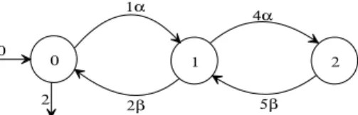
0 1 2
2
1α
2β
4α
5β 0
Figure 4: Deterministic (max,+) automaton.
In the present paper the basic tool for representing discrete event systems is the incidence matrix as defined in the following.
2.3
(max,+) automata and incidence
ma-trices
Definition 8 LetA(max,+)a (max,+) automaton. Its incidence ma-trix represented byA, is defined by
A=[ai,j];ai,j=
tσσ if∃σfrom vertexito vertexj;
ǫ otherwise (34)
wheretσ is the lifetime ofσ. If there is more one event
link-ing stateito statej thenai,j = Lktσkσk is a regular
expres-sion. The initial state is always the state1and is represented by the row vectorΘ(A) = tin ǫ · · · ǫ , wheretin is the
initial delay. The marked states are defined by the column vector
Φ(A) = tm1 tm2 · · · tmn T
, wheretmi represent the
final delays.
Example 8 The (max,+) automaton shown in Figure 4, has the fol-lowing matrix representation
A=
ǫ 1α ǫ
2β ǫ 4α
5β ǫ ǫ
Θ (A) = [ e ǫ ǫ ]
Φ (A) = 2 ǫ ǫ T
(35)
The incidence matrix can also be constructed by
A=
n M
i=1
µ(σi)⊗σi (36)
whereµ(σi) is as defined by Definition 7. Then, the incidence
matrix satisfies all the properties described in the previous section.
Formal languages can be used to construct languages from the timed incidence matrices. The following definition will help the construc-tion of languages.
Definition 9 LetAbe an incidence matrix. An elementai,j =
σ ∈ (Σc∪Σuc)can be interpreted as a path of length1through
which the automaton jumps from stateito statejwith a lifetime equal totσ. Then, the matrix
An=
ntimes
z }| {
A⊗A⊗...⊗A (37)
is a path matrix where each elementan
i,jrepresents one or strings
s =σn· · ·σnof lengthnfrom stateito statejand the total
life-time ists =tσ1+· · ·+tσn. The initial and final vectors ofA n
are the same ofA.
If there is no path from stateito statejthenan i,j=ǫ.
Example 9 The (max,+) automaton shown in Figure 5 can be rep-resented by
A=
ǫ 4α ǫ
5β ǫ 2µ
ǫ 2β 2α
,
Θ (A) = 1 ǫ ǫ ,
Φ (A) = 3 ǫ 2 T
(38)
The path matrixA2for this automaton is
1 2 3
4α
5β
2µ
2α
2β 1
3 2
Figure 5: Strings in a timed incidence matrix: the path matrix of the automaton.
A2=A⊗A=
9αβ ǫ 6αµ
ǫ 4µβ+ 9βα 4µα
7ββ 4αβ 4αα+ 4βµ
(39)
withΘ(A2) = Θ (A)andΦ(A2) = Φ (A). The path matrixA3
is
A3=
ǫ 13αβα+ 8αµβ 8αµα
9µββ+ 14βαβ 6αµβ 6µαα
9αββ 11ββα+ 6ααβ
+6βµβ
6αβµ+ 6ααα
+6βµα
(40)
also withΘ(A3) = Θ (A)andΦ(A3) = Φ (A). In these matri-ces, each element represents a string of length2and3, respectively. The stringαβis recognized since
(y|αβ) = Θ (A)⊗µ(α)⊗µ(β)⊗Φ (A) = 136=ǫ, (41)
Based on these operators it is possible to construct the timed lan-guageL(A)as specified in the following definition.
Definition 10 Given an incidence matrixA, the languageL(A)is
defined by
L(A) =M i
Θ(A)⊗Ai=M
i n M
j=1
θ1(A)⊗ai1,j
, (42)
whereθ1(A)denotes the first element of the initial state row vector Θ (A)andai1,j∈Ai.
The following definition determines how to construct the marked languageLm(A).
Definition 11 Given an incidence matrixA, the languageLm(A)
is defined by
Lm(A) = M
i
Θ (A)⊗Ai⊗Φ (A) (43)
Lm(A) = M
i n M
j|φj(A)6=ǫ
θ1(A)⊗ai1,j⊗φj(A)
(44)
where φj(A) is j-th element of the column vector Φ (A) and
ai
1,j∈Ai.
Example 10 The matrix representation for the automaton shown in Figure 6 is
A=
ǫ 5α
3β κ
,Θ (A) = 1 ǫ ,Φ (A) =
3
e
. (45)
To determine its language we compute
1 2
1
3
5α
3β
κ
e
Figure 6: Timed language of a (max,+) automaton.
A2=
8αβ 5ακ
3κβ 8βα+κκ
A3=
8ακβ 13αβα+ 5ακκ
11βαβ+ 3κκβ 8κβα+ 8βακ+κκκ
.. .
(46)
The elements of these matrices are strings of length2,3, and so on. Multiplying these matrices byθ1(A)we found that
L(A) ={1ε,6α,9αβ,6ακ,9ακβ,14αβα,6ακκ, ...}. (47)
Note thatε ∈ L(A)and tε = 1that is the initial delay of the
automaton. On the other hand, all the strings of lengthiare found at the first line of theAi matrices. By multiplying the first line
Aiby θ1(A)and φk(A) we found the marked language of the
automaton
Lm(A) ={4ε,6α,12αβ,6ακ,12ακβ,14αβα,6ακκ, ...}. (48)
That is the same marked language we obtain by using formal series as given by
Lm(A) = 4ε⊕6α⊕12αβ⊕6ακ⊕12ακβ⊕14αβα⊕6ακκ... (49)
withLm(A) =YRmaxhhΣii.
With these definitions, the languages related to theA(max,+) au-tomaton will be referred asL(A)orLm(A)to make an explicit
reference to its incidence matrix.
The reachability and co-reachability of a (max,+) automaton can be determined from its incidence matrix as defined below.
Definition 12 Thej-th row of an incidence matrixAis said reach-able if∃i,i∈N∗, such that
Θ(A)⊗Ai⊗Π6=ǫ, (50)
whereΠis a column vector, itsj-th element isπj =eand all the
other elements areπk=ǫ,k6=j,k= 1,· · ·,dim (A).
The rowjis said reachable if, starting from the first row, there is at least one strings6=ǫthat leads to rowj.
Definition 13 The row i of an incidence matrix A is said co-reachable if∃k,k∈N∗, such that
Υ⊗Ak⊗Φ (A)6=ǫ, (51)
whereΥis a row vector, itsi-th element isυi = e, and all the
remaining elements areυk=ǫ, k6=i,k= 1,· · ·,dim (A).
The rowiis said co-reachable if, starting from that row, there is, at least, one strings6=ǫthat leads to a marked rowj.
An incidence matrix is said reachable if all its rows are reachable. An incidence matrix is said reachable if all its rows are co-reachable. An incidence matrix is said trim if its both reachable and co-reachable at the same time.
Example 11 The automaton shown in Figure 6 is reachable since
Θ(A)⊗A1⊗Φ = 6α6=ǫ, Φ = ǫ e T, (52)
and
Θ(A)⊗A2⊗Φ = 9αβ6=ǫ,Φ = e ǫ T. (53)
This automaton is also co-reachable since
Φ(A) = 3 e T, (54)
Υ⊗A1⊗Φ(A) = 5α6=ǫ,Υ = e ǫ (55)
Υ⊗A1⊗Φ(A) = 6β6=ǫ,Υ = ǫ e (56)
The equivalence between timed-automata can be defined in terms of its respective incidence matrices as shown below.
Definition 14 LetAandBdenote two timed matrices, such that
∀ai,j,ai,j ∈Σ ∗,∀b
i,j,bi,j ∈Σ
∗. These matrices are said
equiva-lent, denoted byA≡B, if for any two timed stringssA(A)and
sB(B), such that(yA|sA) = (yB|sB), there exists aσ∈Σthat is feasible both inAandB, such that(yA|sAσ) = (yB|sBσ).
Example 12 The timed matricesA1andA2are equivalent
A1=
ǫ 2α ǫ
2λ ǫ 3β
ǫ 3β ǫ
,Θ (A1) = 2 ǫ ǫ ,
Φ (A1) =
ǫ
3 3
,A2=
ǫ 2α
2λ 3β
Θ (A2) = 2 ǫ ,Φ (A2) =
ǫ
3
(57)
and thus exhibit the same timed language
L(A1) =L(A2) ={2ε,4α,6αλ,8αλα,7αβ,10αββ,· · · } (58)
and its respective automata recognize the same marked language
Lm(A1) =Lm(A2) ={7α,11αλα,7αβ,10αββ,· · · } (59)
The automata represented by these two matrices are shown in Fig-ure 7.
1 2 3
1 2
2α 3β
3β
3β 2α
2λ
2λ
A
A
1
2
2
2
3 3 3
(max,+) (max,+)
2λ
Figure 7: Two equivalent (max,+) automata.
2.4
Synchronous composition
To define the synchronous composition in terms of the timed inci-dence matrices it is necessary to introduce the following operator.
Definition 15 Given a dioidD=RmaxhhΣii, the operator⊛ def-ines the intersection between elements as
a⊛b= k M
i=1 (tσi⊕t
′
σi)σi, iftσiσi⊂a∧t ′
σiσi⊂b. (60)
∀a, b∈D, where
tσσ⊛ǫ=ǫ
tσ1σ1⊛tσ2σ2=ǫ
tσσ⊛t′σσ= (tσσ⊕t′σσ)σ,
(61)
∀σ, σ1, σ2 ∈Σand∀tσ, tσ1, tσ2, t
′
σ ∈Rmax. For timed incidence matrices the intersection operation is defined by
C=A⊛B, ci,j=ai,j⊛bi,j, (62)
whereai,j⊛bi,jis as defined above with
Θ (C) = Θ (A)⊛Θ (B) andΦ (C) = Φ (A)⊛Φ (B). (63)
From this definition and considering that the elements ofΘ (·)and
Φ (·)belong toRmax, the⊛operation is equivalent to the⊕ oper-ation. However, when dealing with the control of a DES this def-inition must be restricted since the alphabet of events is partitioned
as Σ = Σc ∪Σuc and only the controllable eventsΣuccan be
delayed by the supervisor.
Definition 16 Consider that the incidence matrixAdenotes the de-sired timed behavior for a given timed DES represented by an in-cidence matrix B. The elements of the matricesA andB (ai,j
andbi,j) can be regular expressions liketσ1σ1+...+tσkσkand t′
σ1σ1 +...+t
′
σkσk, respectively. In this case theai,j ⊛bi,j is
defined by
ai,j⊛bi,j=
Lk i=1(tσi⊕t
′
σi)σi if (tσiσi⊂ai,j)∧t ′
σiσi⊂bi,j
∧(σi∈Σc) Lk
i=1t
′
σiσi if (tσiσi⊂ai,j)∧t ′
σiσi⊂bi,j
∧(σi∈Σuc).
(64)
The⊛operator as defined previously can be employed in the super-visor synthesis algorithm as it will be shown in the following.
To deal with the possibility of having uncontrollable events with variable lifetimes the synchronous product of timed incidence ma-trices must be defined as follows:
Definition 17 Given two timed incidence matricesA,dim (A) =
m, andBn×n,dim (B) = n, corresponding, respectively, to the automatonA(max,+)with an alphabet of eventsΣAand to the
au-tomatonB(max,+)with an alphabet of eventsΣB. The timed
inci-dence matrixP,dim (P) = q = mnand an alphabet of events given byΣ = ΣA∪ΣBcorresponding to the automaton resulting
from the synchronous composition of these two automata is defined as
wherek=iA+m(iB−1)andl=jA+m(jB−1)such that P=
b1,1⊛[a1,1a1,2...a1,n] ... b1,m⊛[a1,1a1,2...a1,n]
..
. ... ...
b1,1⊛[an,1an,2...an,n] ... b1,m⊛[an,1an,2...an,n]
b2,1⊛[a1,1a1,2...a1,n] ... b2,m⊛[a1,1a1,2...a1,n]
..
. ... ...
b2,1⊛[an,1an,2...an,n] ... b2,m⊛[an,1an,2...an,n]
..
. ... ...
bm,1⊛[a1,1a1,2...a1,n]... bm,m⊛[a1,1a1,2...a1,n]
..
. ... ...
bm,1⊛[an,1an,2...an,n]... bm,m⊛[an,1an,2... an,n] (66)
ifΣA = ΣB. The marked states of the composite automaton are
defined by a column vectorΦq×1(P)and itsk-th element is given by
φk(P) =φiA(A)⊛φiB(B), (67)
withk=iA+m(iB−1). The initial state vector of the composite automaton a row vector defined as
Θ1×q(P) = θ1(A)⊕θ1(B) ǫ · · · ǫ . (68)
If∃σA∈/ΣA, or∃σB∈/ΣB, such thatΣA∩ΣB6=∅, then
Pq×q= (A||B)⊕C¬, (69)
where
C¬=
A¬B⊕D¬A
(b1,1)
D¬A
(b1,2) ...
D¬A
(b1,n)
D¬A
(b2,1)
A¬B⊕D¬A
(b2,2)...
D¬A
(b2,n)
D¬A
(b3,1)
D¬A
(b3,2) ... .. .
..
. ... ... D¬A
(bn−1,n)
D¬A
(bn,1)
D¬A
(bn,2) ...
A¬B⊕D¬A
(bn,n) (70)
dim (C¬) =m×n,A¬Bis the matrix with elements ofΣ
Athat
does not belong toΣA andD¬(bA
i,j) is a matrix having dimension m×msuch that its diagonal contains the elementsbi,jnot defined
inAwhileǫis put in all the other elements.
The algorithm for constructing the synchronous productP=A||B
of two timed incidence matrices is given below:
Algorithm 1 Algorithm for constructing the synchronous product
P=A||B
1. jA←1; 2. jB←1; 3. iA←1; 4. iB←1;
5. θ1(P)←θ1(A)⊕θ1(B); 6. whileiB≤n, do:
a) ifbiB,jB =ǫ, dojB←jB+ 1;
b) ifjB> n, doiB←iB+ 1andjB←0;
c) whileiA≤m, do:
i. ifaiA,jA =ǫ, dojA←jA+ 1;
ii. ifjA> m, doiA←iA+ 1andjA←0;
v. k←iA+m(iB−1);
vi. l←jA+m(jB−1);
vii. pk,l←aiA,jA⊛biB,jB; viii. φk(P)←φiA(A)⊛φiB(B); ix. jA←jA+ 1;
x. ifjA> m, doiA←iA+ 1andjA←0;
d) jB←jB+ 1;
e) ifjB> n, doiB←iB+ 1andjB←0;
7. if∃σA∈/Σ2or∃σB∈/Σ1, makeC¬, and dopk,l←pk,l⊕c¬k,l.
Remark 1 This algorithm is very similar to the algorithm em-ployed for the synchronous composition of un-timed automata. The computational complexity of this algorithm has the order of
O(nm).
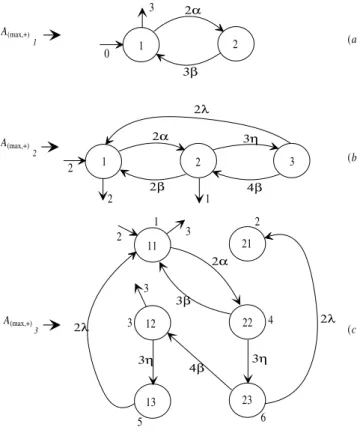
Example 13 Given
A=
ǫ 2α
3β ǫ
, Θ (A)= e ǫ , Φ(A)=
3 ǫ , (71) B=
ǫ 2α ǫ
2β ǫ 3η
2λ 4β ǫ
,Θ (B)=2 ǫ ǫ,Φ(B)=
2 1 ǫ (72)
representing the automata shown in Figures 8(a) and 8(b), re-spectively, the synchronous product matrixPcan be determined. The elements of such matrix defined bypk,l = p(iA,iB),(jA,jB),
k=iA+m(iB−1)andl=jA+m(jB−1)whenaiA,jA =
biB,jB 6=ǫ, are given by
• k= 1 + 2×0 = 1,l= 2 + 2×1 = 4,p1,4=p(1,1),(2,2)=
a1,2⊛b1,2= 2α
• k= 2 + 2×1 = 4,l= 1 + 2×0 = 1,p4,1=p(2,2),(1,1)=
a2,1⊛b2,1= 3β
• k= 2 + 2×2 = 6,l= 1 + 2×1 = 3,p6,3=p(2,3),(1,2)=
a2,1⊛b3,2= 4β
P=
ǫ ǫ ǫ 2α ǫ ǫ
ǫ ǫ ǫ ǫ ǫ ǫ
ǫ ǫ ǫ ǫ ǫ ǫ
3β ǫ ǫ ǫ ǫ ǫ
ǫ ǫ ǫ ǫ ǫ ǫ
ǫ ǫ 4β ǫ ǫ ǫ
Θ (P) = 2 ǫ ǫ ǫ ǫ ǫ ,
Φ(P) = 3 ǫ 3 ǫ ǫ ǫ T
1 2
1 2 3
11 21 12 22 13 23 6 5 4 3 2 1 2α 3β 2λ 4β 3η 2β 2α 2α 3β 4β 2λ 2λ 3η 3η
(c)
A 3 2 1
(b) (a)
2 3 2 1 2 3 3 0 (max,+) A(max,+) A(max,+)
Figure 8: Illustrating the use of the synchronous composi-tion: (a)A(max,+)1, (b)A(max,+)2and (c)A(max,+)3.
Considering thatλ, η ∈ B, but λ, η /∈ A, it is required to
build the matrixC¬given by
C¬=
A¬B⊕D¬A
b1,1
z }| {
ǫ ǫ ǫ ǫ
D¬A
b1,2
z }| {
ǫ ǫ ǫ ǫ
D¬A
b1,3
z }| {
ǫ ǫ ǫ ǫ
D¬A
b2,1
z }| {
ǫ ǫ ǫ ǫ
A¬B⊕D¬A
b2,2
z }| {
ǫ ǫ ǫ ǫ
D¬A
b2,2
z }| {
3η ǫ
ǫ 3η
D¬A
b3,1
z }| {
2λ ǫ
ǫ 2λ
D¬A
b3,2
z }| {
ǫ ǫ ǫ ǫ
A¬B⊕D¬A
b1,1
z }| {
ǫ ǫ ǫ ǫ (74) and thus
P=P⊕C¬=
ǫ ǫ ǫ 2α ǫ ǫ
ǫ ǫ ǫ ǫ ǫ ǫ
ǫ ǫ ǫ ǫ 3η ǫ
3β ǫ ǫ ǫ ǫ 3η
2λ ǫ ǫ ǫ ǫ ǫ
ǫ 2λ 4β ǫ ǫ ǫ
(75)
whereΘ (P)and Φ (P) are given by (73). Finally, matrix
Ptogether withΘ (P)and Φ (P) represent the automaton
A(max,+)3shown in Figure 8(c).
It must be noted that all the elements of row2are such that
p2,j =ǫand it can be reached after the strings= Θ (P)⊗
P3⊗π=p1,4p4,6p6,2= 9αηλ, for
π= ǫ e ǫ ǫ ǫ ǫ T. (76)
This shows that from the composition of A(max,+)1 with
A(max,+)2may result an automaton with a blocking state.
Remark 2 The definition 17 establishes that the composition of two automaton whenΣA∩ΣB=∅requires the determination of the matrixC¬. It is worth noting that such composition is based on the operator⊛(see Definition 15). However, when the alphabet of eventsΣis partitioned into controllableΣcand uncontrollable
eventsΣuc, the intersection operator⊛must be redefined according
to Definition 16.
3
TIME-VARYING AUTOMATON
Based on the formalism outlined the previous sections we introduce here an extended version of the (max,+) automaton named time-varying automaton (TVA).
Definition 18 A time-varying automaton TVA over an alphabetΣ
is a quintuple given by
T V A= (Q,Σ, q0, t0, ti, tf), (77)
where:
• Q={q0, ..., qn}is a finite set of states; • Σ ={σ1, ..., σm}is an alphabet of events; • q0is the initial state;
• t0:q0→Rmaxis the initial delay;
• ti:ti−1×Q×Σ×Q→Rmaxis the transition function and
• tf :ti−1×Q→Rmaxis the final delay function.
The graphical representation of an TVA is a graph constituted by vertices representingQand three types of arcs:
1. Internal arcsqj σ
→ qj+1,∀qj, qj+1 ∈ Q,σ ∈ Σsuch that
ti6=ǫ. Theqj→σ qj+1is valued byti=f(ti−1); 2. Input arc→q0valued byt06=ǫ;
3. Output arcsqj →valued bytf, ∀qf ∈ Qsuch thattf =
f(tj−1)6=ǫ.
Note that the (max,+) automaton is simply a special case of the TVA automaton when all the transition functions are considered to be constants. Then, consequently, the dynamics of the TVA is quite similar to the dynamics of the (max,+) automaton.
2. Given that the automaton reached statei−1, then it will jump to stateiafter the occurrence ofσ, however the eventσwill be enabled to occur only aftertiunits of time. In a TVAtiis
not constant as in a (max,+) automaton but depends onti−1, i.e.,ti=f(ti−1).
3. The initial stateq0 ∈Qwill be reached only aftert0units of time with respect to the global clock time origin;
4. When the automaton reaches a given stateithe counters asso-ciated to eventsti(σ)all start decrementing simultaneously.
When a given counter reaches zero it stops decrementing and the respective event becomes enabled and may occur from now on;
5. When a given event occurs all the running counter are stopped and the state of the automaton changes;
6. If at a given stateithere are two arcs leaving that state and the labels are equal but valued with different transition times then the TVA is said non-deterministic.
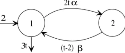
Example 14 LetΣ ={α, β},Q={1,2,3},t0 = 2, the follow-ing transition functions
f1(t) =t2−t,
f2(t) = 3t,
f3(t) = 4,
f4(t) = 1 + 2t
(78)
and the final delay function
f5(t) = 5−2/t. (79)
The other transition functions are equal toǫ. The corresponding au-tomaton is shown in the Figure 9. Thetin the above expressions is measured in units of time (of a given time base) must be interpreted as the last lifetime, i.e.,ti−1as explained previously. The value of the lifetime forαrelated with the arcq1→α q2is
t1=f1(2) = 2, (80)
sincet0= 2. The final delay for recognizingε(ifαdoes not occur) is
tf =f5(2) = 4, (81)
and consequently the total time it takes for recognizingεis6units of time. However, ifαoccurs the automaton jump to state2where the lifetime forαis
t2=f2(2) = 6 (82)
and the lifetime forβis
t2=f4(2) = 5. (83)
If at state 2, αoccurs the automaton jumps to state3where the lifetime forβis
t3=f3(5) = 4. (84)
If at state2,β occurs the automaton jumps to state1where the lifetime forαis
t3=f1(6) = 30, (85)
the final delay for recognizingαβis
tf =f5(5) = 4.6, (86)
and consequently the total time it takes for recognizingαβis13.6
units of time.
It is worth noting that the recognition of a given string occurs when a marked state is reached and the final delay has passed. This string recognition process can also be described by the daters of the strings as presented in the following:
Definition 19 A dater is a map given by
Y : Σ∗→Rmax, (87)
whereY is the time it takes for the string
s=σ1σ2...σn∈Σ∗. (88)
to be processed within a TVA.
The dater defines the lifetimes related to the strings ofΣ∗.
Conse-quently, a TVA takesY units of time to change its state fromqtoq′
by processings, where(y|s)denotes the value ofY for the string
s.
Definition 20 A dater is said recognized if there exists a TVA such that
(y|s)6=ǫ. (89)
Example 15 For the automaton of the Example 14, we can see that
s=αβis a recognized string since
(y|αβ) = (t0+f1(t0) +f4(t1) +tf) = 13,66=ǫ. (90)
3.1
TVA and formal series
The use of formal series to define the dynamics of a TVA is quite similar what has been done for the (max,+) automaton. Thus, it follows that:
Definition 21 A timed language
L={tss, ts′s′, ...}, (91)
withs, s′, ...∈Σ∗andts, ts′, ...∈Rmax, can be represented by a formal series
YRmaxhhΣii=
M
s∈Σ∗
(y|s)s, (92)
where
RmaxhhΣii (93)
denotes the semi-ring of the formal series having coefficients in
Rmaxand non commutative variables inΣ.
Example 16 The languageL = {3ε,4α,2αβ,3βα}overΣ =
{α, β}can also be represented by
YRmaxhhΣii= 3ε⊕4α⊕2αβ⊕3βα= 3⊕4α⊕2αβ⊕3βα (94) sinceǫ⊗L = ǫ,∀L ⊆ Σ∗. This series represents the language
recognized by a TVA. The term(y|s)denotes the coefficient of the stringsthat is equal to ‘ǫ’ ifsis not recognized by the TVA.
According to this formalism, a dater functionY can be described by using a formal series defined overΣwith coefficients defined in
Definition 22 A timed language of a TVA is defined by a formal series
L(T V A) = M s∈Σ∗
(y|s)s, (95)
where(y|s)∈Rmaxdenotes the dater of the strings∈Σ∗.
Example 17 For the automaton of the Example 14, the formal se-riesYRmaxhhΣiirelated to the recognized timed language is given by
YRmaxhhΣii= 6⊕13,6αβ⊕74,95αβαβ⊕27,78ααββ⊕... (96)
3.2
TVA and incidence matrices
The definition of an incidence matrix for a TVA follows similar rules as it was done for the (max,+) automaton. However, instead of fixed lifetimes, the elements of the incidence matrix will be related with the transition functions as shown in the following:
Definition 23 Given a TVA, its incidence matrix, denoted byA, is defined as
A=[ai,j];ai,j=
f(tσ)σ if∃σfrom vertexito vertexj;
ǫ otherwise, (97)
wheref(tσ)represents the lifetime of eventσ. The automaton
jumps from stateito statejupon the occurrence ofσ. If more than one string may provoke the jump from stateito statejthen the respective element of the matrix must be written as a timed regular expression likeai,j = Lkf(tσk)σk. For mathematical
conve-nience, the state1is always considered as the initial state and can be represented by the row vectorΘ(A) = [ t0 ǫ ... ǫ ], the
marked states are also represented by the column vectorΦ(A) = [ f(tf1) f(tf2) ... f(tfn) ]
T
.
Example 18 The TVA shown in Figure 9 has the following matrix representation
A=
ǫ (t2-t)α ǫ
(1+2t)β ǫ (3t)α
ǫ 4β ǫ
,Θ(A)=[2ǫ ǫ],Φ(A)=
5-2/t
ǫ ǫ
(98)
Thetin the above matrices and vectors is measured in units of time (of a given time base) and must be referred to the last transition time.
1 2
α
β
α
β 3 2
f 1(t) f 2(t)
f 3(t)
f 4(t)
f 5(t)
Figure 9: Example of a time-varying automaton.
All the matrix formalisms already presented for the (max,+) are also valid for the time-varying automaton. However, when defining lan-guages by using path matrices we must consider that the lifetimes change at every automaton execution as illustrated by the following example:
Example 19 The matrix representation for the TVA shown in Fig-ure 10 is given by
A=
ǫ 2tα
(2-t)β ǫ
, Θ (A)=2 ǫ, Φ (A)=
3t
ǫ
(99)
The path matrixA2for this automaton is given by
A2=A⊗A=
((2t1) + (t2-2))αβ ǫ
ǫ ((t2-2) + (2t3))βα
(100)
whereΘ(A2) = Θ (A)andΦ(A2) = Φ (A). Note that some ele-ments ofA2contain different lifetimes since everytiis calculated
separately.
1 2
α
β 2
3
2t
(t-2) t
Figure 10: Time-varying automaton for illustrating how to construct the path matrix.
For the proposed TVA formulation the language definitions given in 10 and 11, the definitions for reachability, co-reachability as well as the automata composition operator defined previously for the (max,+) automaton are also valid.
4
SUPERVISOR SYNTHESIS
The so calledSupC(L) algorithm (Ramadge e Wonham, 1987a) pro-vides a procedure for synthesizing a supervisor for a DES. The syn-thesis of a timed (fixed lifetime) supervisor based on this algorithm has already been proposed (Brandin e Wonham, 1994). The su-pervisor synthesis as proposed in the present article is also based on theSupC(L) algorithm but allows one to consider variable event lifetime. The following definitions are required in order to state the proposed synthesis procedure:
Definition 24 Given an alphabet of eventsΣ, partitioned intoΣ = Σc∪Σuc, and an timed incidence matrixA, we can define its
un-controllable timed incidence matrixAucby
Auc=h(auc)i,j
i
; (101)
(auc)i,j=
f(tσuc)σuc if∃σucfrom vertexito vertexj;
ǫ otherwise, (102)
wheref(tσuc)represents the lifetime ofσuc. The automaton jumps
from stateito statej upon the occurrence ofσuc. If more than
one string may provoke the change from stateito statejthen the respective element of the matrix must be written as a time regular expression like(auc)i,j =
L
lf(tσl)σl. The initial state and the
The desired behavior for the closed-loop DES, usually denoted by specification, is an essential input information for any supervisor synthesis procedure.
Definition 25 The specification for a TVA is denoted by a matrix
Edefined by
E= [ei,j];ei,j=
f(tσ)σ if∃σfrom vertexito vertexj;
ǫ otherwise, (103)
wheref(tσ) represents the lifetime ofσ. The automaton jumps
from statei to statej upon the occurrence of σ. If more than one string may provoke the change from stateito statejthen the respective element of the matrix must be written as a time regu-lar expression likeei,j = Llf(tσl)σl. For mathematical
conve-nience, the state1is always considered as the initial state and can be represented by the row vectorΘ (E) = [ t0 ǫ ... ǫ ], the marked states are also represented by the following column vector
Φ(E) = [ f(tf1) f(tf2) ... f(tfn) ]
T. If the statekis not
a marked state, thenf(tfk) =ǫ.
Definition 26 A supervisor synthesized for a given specificationE
is also defined as a matrix
S=[sti,j],sti,j=
f(tσ)σ⊂ei,jiff(tσ)σ⊂ei,jis allowed inA;
ǫ otherwise (104)
wheresti,j = ǫforai,j 6= ǫ, indicates that either it is possible
to prevent the occurrence the event enabled atai,j,ai,j ∈ Σcor
that the statej(row j) its not reachable. If more than one string is allowed at ai,j thensti,j = Llf(tσl)σl. For mathematical
convenience, the state1is always considered as the initial state and can be represented by the row vectorΘ (S) = [ t0 ǫ ... ǫ ] the marked states are also represented by the column vectorΦ(S) =
[ f(tf1) f(tf2) ... f(tfn) ]
T. If the statekis not a marked
state, thenf(tfk) =ǫ.
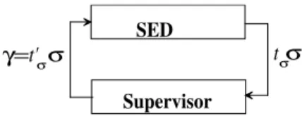
The control action of the timed supervisor is executed as follows: the supervisor observes the events and its respective lifetimes and determines the control input for the DES by delaying the occurrence of the controllable events as illustrated in Figure 11.
SED
Supervisor
t
σσ
γ=
t'
σσ
Figure 11: Supervision of a timed DES.
The set of control inputs for the timed supervisor is defined by:
Definition 27 The set of control inputs for a timed supervisor is defined by
Γ ={γ1, γ2, ...}, (105) where
γi=f(t
′
σk)σk,∀σk∈Σ (i), k= 1,2, ..., (106)
with
f(t′σk) =f(tσk),∀σk∈Σuc (f(t′σk)≥f(tσk)),∀σk∈Σc.
(107)
The meaning off(t′σk) ≥f(tσk)is thatσkwill inhibited byt= f(t′σk)−f(tσk)units of time, i.e., the lifetime is increased.
According to the definition 27, the control input provided by the timed supervisor isγ = f(t′σ)σ that defines what are the
en-abled events in a given state as well as its respective lifetimes (f(t′σ)≥f(tσ)). In other words, the supervisor may inhibit a given
event at a given state byf(t′σ)−f(tσ)units of time or block
com-pletely its occurrence iff(t′σ) =ǫ. The dynamics of the supervised
time system can be studied either by constructing the recognized language through formal series or by using the synchronous com-position ofS||Aas obtained according to Definition 11.
In order to make a formal binding of the proposed approach with the standard supervisory control theory it is important to consider the following remarks:
1. A automaton has a similar structure but contains a sub-set of the states or a sub-sub-set of the arcs of a given automaton. The lifetimes associated to the arcs of the sub-automaton must be greater than or equal to the respective lifetimes of a given automaton;
2. A timed sub-language presents a sub-set of the strings of a given timed language. The lifetimes associated to the strings of the sub-language must be greater than or equal to the re-spective lifetimes of the strings of the language. Given that
L′ ⊂ Lthis does not necessarily imply that the automaton built for recognizingL′ is a sub-automaton of the automaton built for recognizingL;
3. A sub-matrix is formed by the first m rows and first m
columns of a given incidence matrix. The sub-matrix has an elementwise relationship with the matrix but considering that the lifetimes of its elements are greater or equal to the respec-tive lifetimes of the elements of the matrix.
In order to synthesize the timed supervisor as proposed in the present paper it is required that the incidence matrix representing the specification be a sub-matrix of the incidence matrix represent-ing the DES; i.e.,Emust be a sub-matrix ofA. If this is not the case we must transformAintoA#and buildE#to be a sub-matrix of
A#such that
L(A#) = L(A) L(E#) = L(E).
By doing this, wheneverEis a sub-matrix ofA, or due to the sug-gested transformationE#is a sub-matrix ofA#, the following or-der relationship
L(E)⊆L(A) (108)
is always satisfied.
1. Build a synchronous composition ofAwith a matrixE∗that generatesΣ∗to createA#such that
L(A#) =L(A). (109)
The matrixE∗is derived fromEby adding to it a forbidden state (rowie/columnje), named error state. Then the matrix
A#is obtained by
A#=A||E∗; (110)
2. The matrixE#is obtained fromA#by making all the ele-ments of the form(iA, ie) =ǫand(jA, je) = ǫ. By doing
this, the matrixE#is such that
L(E#)⊂L(A#) =L(A), (111)
with
L(E) =L(E#) (112)
and such thatE#is a sub-matrix ofA#;
3. The lifetimes forEare used to determine the lifetimes forE#
(that are equal to the lifetimes ofA) by computingtσ⊕t
′
σ,
wheretσ is the lifetime ofσ ⊂ ei,j andt
′
σ is the lifetime
ofe#k,l, forkrepresenting the pair(iA, iE)foriE =iandl representing the pair(jA, jE)forjE=j;
4. The vectorΘ(E#)is obtained fromΘ (E)by
θ1(E#) =θ1(E#)⊛θ1(E) ; (113)
5. The vectorΦ(E#)is also determined fromΦ (E)by
φk(E#) =φk(E#)⊛φi(E) (114)
where k represents the pair (iA, iE) with i = iE and
φi(E)6=ǫ.
Following these steps,E#will be a sub-matrix ofA#and conse-quently
L(E#) ⊂ L(A#) =L(A)
L(E#) = L(E).
Remark 3 The lifetimes for E∗ must be tσ = e such that
L(A) =L(A||E∗).
The transformation ofEintoE∗and the transformation ofEinto
E#, respectively can be achieved with following algorithms:
Algorithm 2 Algorithm for transformingEintoE∗
1. ∀i, doφi(E)←e, and
∀ei,j=f(tσ1)σ1+...+f(tσn)σn, (115)
do
f(tσk)←e, k= 1, ...,dim (E) ; (116)
2. for each row i of E, include the self-loops ei,i = Σ− {σ1, σ2, ..., σn}, such thatσk6⊂ei,j, k= 1,2, ...,dim (E);
3. makedim (E) ← dim (E) + 1, where (i,dim (E)) and
(dim (E), j) are the elements of the error row/column
(ie/je);
4. θdim(E)(E)←ǫ; 5. φdim(E)(E)←e; 6. fori= 0untili < ie, do:
a) forj= 0untilj < je,do: i. fork= 0untilk < je,do:
I) ifσ⊂ej,i∨σ⊂ej,jandei,k6=σdoei,je ←σ; ii. ifei,j 6=σ
′
doei,je←σ
′
;
7. eie,je←Σ.
Algorithm 3 Algorithm for transformingEintoE#
1. TransformEinE∗;
2. ConstructA#=A||E∗;
3. fori= 1untiln×mdo:
i. forj= 1untiln×m, do:
a) ifa#i,j6=ǫ, doe#i,j←a#i,j.
4. fork= 1untiln×m:
a) ifφk A#6=ǫ, do
iE←((k−(kmodm))/m) + 1, (117)
and
φk
E#←φk
E#⊛φiE(E) ; (118)
5. doθ1 E#←θ1 E#⊛θ1(E).
In this algorithmmodis the operator that determines the remainder of the divisionk/m. The step 4 of this algorithm define the final delays and step 5 defines the initial delay in order to make sure that
L E#=L(E)andLm E#
=Lm(E).
The use of these algorithms will be illustrated by an example where the transition functions of the TVA are constants, like in a (max,+) automaton.
Example 20 Consider the matrix
A=
ǫ 2α1 3α2 ǫ
2β1 ǫ ǫ 3α2
4β2 ǫ ǫ 2α1
ǫ 4β2 2β1 ǫ
,
Θ(A)=3 ǫ ǫ ǫ,
Φ(A)=e ǫ ǫ 3T
and the desired specification
E=
α1+β2 5β1
4α2 α1+β2
, Θ (E) =
4 ǫ ,
where Σuc = {β1, β2}. To build E# such that L E# ⊂
L A# = L(A)we first createE∗that generatesΣ∗. In this
case
E∗=
α1+β2 β1 α2
α2 α1+β2 β1
ǫ ǫ α1+β1+α2+β2
,
Θ (E) = e ǫ ǫ ,Φ (E) = e e e T
where the error row/column is the third one. Now computingA||E∗
we obtain
A#=
ǫ 2α1 ǫ ǫ ǫ ǫ ǫ ǫ ǫ ǫ 3α2 ǫ
ǫ ǫ ǫ ǫ 2β1 ǫ ǫ ǫ ǫ ǫ ǫ 3α2
4β2 ǫ ǫ 2α1 ǫ ǫ ǫ ǫ ǫ ǫ ǫ ǫ
ǫ 4β2 ǫ ǫ ǫ ǫ 2β1 ǫ ǫ ǫ ǫ ǫ
ǫ ǫ 3α2 ǫ ǫ 2α1 ǫ ǫ ǫ ǫ ǫ ǫ
ǫ ǫ ǫ 3α2 ǫ ǫ ǫ ǫ 2β1 ǫ ǫ ǫ
ǫ ǫ ǫ ǫ 4β2 ǫ ǫ 2α1 ǫ ǫ ǫ ǫ
ǫ ǫ ǫ ǫ ǫ 4β2 ǫ ǫ ǫ ǫ 2β1 ǫ
ǫ ǫ ǫ ǫ ǫ ǫ ǫ ǫ ǫ 2α13α2 ǫ
ǫ ǫ ǫ ǫ ǫ ǫ ǫ ǫ 2β1 ǫ ǫ 3α2
ǫ ǫ ǫ ǫ ǫ ǫ ǫ ǫ 4β2 ǫ ǫ 2α1
ǫ ǫ ǫ ǫ ǫ ǫ ǫ ǫ ǫ 4β22β1 ǫ
Θ(A#) =3ǫ ǫ ǫ ǫ ǫ ǫ ǫ ǫ ǫ ǫ ǫ,
Φ(A#) =e ǫ ǫ 3 e ǫ ǫ 3e ǫ ǫ 3T
and then we getE#as given by
E#=
ǫ 2α1 ǫ ǫ ǫ ǫ ǫ ǫ ǫ ǫ ǫ ǫ
ǫ ǫ ǫ ǫ 2β1 ǫ ǫ ǫ ǫ ǫ ǫ ǫ
4β2 ǫ ǫ 2α1 ǫ ǫ ǫ ǫ ǫ ǫ ǫ ǫ
ǫ 4β2 ǫ ǫ ǫ ǫ 2β1 ǫ ǫ ǫ ǫ ǫ
ǫ ǫ 4α2 ǫ ǫ 2α1 ǫ ǫ ǫ ǫ ǫ ǫ
ǫ ǫ ǫ 4α2 ǫ ǫ ǫ ǫ ǫ ǫ ǫ ǫ
ǫ ǫ ǫ ǫ 4β2 ǫ ǫ 2α1 ǫ ǫ ǫ ǫ
ǫ ǫ ǫ ǫ ǫ 4β2 ǫ ǫ ǫ ǫ ǫ ǫ
ǫ ǫ ǫ ǫ ǫ ǫ ǫ ǫ ǫ ǫ ǫ ǫ
ǫ ǫ ǫ ǫ ǫ ǫ ǫ ǫ ǫ ǫ ǫ ǫ
ǫ ǫ ǫ ǫ ǫ ǫ ǫ ǫ ǫ ǫ ǫ ǫ
ǫ ǫ ǫ ǫ ǫ ǫ ǫ ǫ ǫ ǫ ǫ ǫ
Θ(E#) =4ǫ ǫ ǫ ǫ ǫ ǫ ǫ ǫ ǫ ǫ ǫ,
Φ(E#) =2 ǫ ǫ ǫ ǫ ǫ ǫ ǫ ǫ ǫ ǫ ǫT
Note that onlyφ1(E#)6=ǫsinceφ1(E#) =φ1(A)⊛φ1(E).
In order to synthesize the timed supervisorSit is required to intro-duce the following operators:
Definition 28 TheACESoperator is defined as
ACES(A) =B, bi,j=
ai,j ifiis reachable
ǫ otherwise. (119)
The operationACES(A)eliminates all the elementsai,jof a
non-reachableirow. For a given matrixF, theACESoperator can be implemented by the following algorithm:
Algorithm 4 ACESOperator
1. Create a vectorvac1×Nof reachable states.
2. fori= 1untilN, do:
a) forj= 1untilN, do:
i. ifF(1, j)6=ǫ, dovac(j)←1.
ii. ifi > 1andF(i, j) 6=ǫandvac(i) = 1, then do
vac(j)←1. 3. fori=N−1until1, do:
b) forj= 1untilN, do:
i. ifF(i, j)6=ǫandvac(i) = 1, then dovac(j)←1. 4. fori= 1untilN, do:
a) forj= 1untilN, do:
i. ifvac(i) = 0, doF(i, j)←ǫ.
Definition 29 TheCOACESoperator is defined as
COACES(A) =B,
bi,j=
ai,j if∃s|s=ai,j1aj1,j2...ajn−1,jn,
ai,j1,aj1,j2,..., ajn−1,jn6=ǫ andφjn(A)=e; ǫ otherwise
(120)
TheCOACES(A)operation eliminates the elements that lead to non-reachable rows. For a given matrixF, theCOACESoperator
can be implemented by the following algorithm:
Algorithm 5 COACESOperator
1. Create a vectorvcoN×1of coreachable states. 2. fori= 1untilN, do:
a) forj= 1untilN, do:
i. ifF(1, j)6=ǫandφj(F) =e, dovco(i)←1. ii. if i > 1 and F(i, j) =6 ǫand (φj(F) = e or
vco(j) = 1), then dovco(i)←1. 3. forj= 1untilN, do:
b) fori=N−1until1, do:
i. ifF(i, j)6=ǫand(φj(F) =eorvco(j) = 1), then
dovco(i)←1. 4. Forj= 1untilN, do:
a) fori= 1untilN, do:
i. ifvco(j) = 0, doF(i, j)←ǫ.
Definition 30 The operatorT RIMis defined by
T RIM(A) =ACES(COACES(A)) =B. (121)
The use of theT RIM operator for a given incidenceAyields an
incidence matrixBthat is both reachable and co-reachable.
Definition 31 Given two timed incidence matricesA= [ai,j]and
B= [bi,j], the operatorEis defined by
AEB⇒L(A)⊆L(B). (122)
Similarly, the operatorsD,⊳and⊲can be defined by
ADB⇒L(A)⊇L(B),
A⊳B⇒L(A)⊂L(B),
A⊲B⇒L(A)⊃L(B).
(123)
Based on definition 31, and considering a generic elementσ =
f(tσ1)σ1+...+f(tσn)σn, the determination ofAEBcan be achieved through the following algorithm:
Algorithm 6 Algorithm for determiningAEB
1. fori= 1untilN, do:elementoai,jfac¸a: i. forj= 1untilN, do:
a) ifσ /∈Bandai,j=σ, thenA6EB; b) if
ai,j=t
′
σhσh+...+t
′
σkσk, t
′
σi ≥tσi
∨
(ai,j=ǫ), whereσi, ..., σk ⊂σandbi,j=tσσ,
thenAEB;
2. ifθ1(A)≥θ1(B), thenAEB. 3. fori= 1untilN, do:
i. if(φi(A)≥φi(B))or(φi(A) = ǫ∧φi(B) 6= ǫ)or (φi(A) =ǫ∧ ∀φi(B) =ǫ), thenAEB.
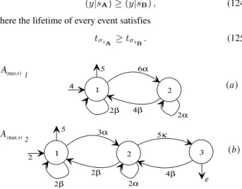
The conditionAEBimplies the execution time of every sequence inA(string of events with its respective lifetimes) must be greater than or equal to the execution time of the same sequence inB. In other words, given two timed languagesL(A)andL(B)this
con-dition also implies thatL(A)⊆L(B), i.e., the execution time of a given timed language is always less than or equal to the execution time of any sub-language of that language (Alur e Dill, 1990; Alur e Dill, 1994; Alur, 1997). Equivalently,
(y|sA)≥(y|sB), (124) where the lifetime of every event satisfies
tσiA ≥tσiB. (125)
1 2
6α
2α 4β
2β
1 2 3
3α 5κ
2β 4β
(a)
(b)
A 1
2
4 5
(max,+)
A(max,+)
2 5
2β 2α e
Figure 12: (max,+) automata for illustrating the use of the⊳ operator.
Example 21 The automaton shown in Figure 12(a) has the follow-ing matrix representation
A1=
2β 6α ǫ
4β 2α ǫ
ǫ ǫ ǫ
, Θ (
A1) = 4 ǫ ǫ ,
Φ(A1) = 5 ǫ ǫ T
and the automaton shown in Figure 12(b) has the following matrix representation
A2=
2β 3α ǫ
2β 2α 5κ
ǫ 4β ǫ
, Θ (
A2) = 2 ǫ ǫ ,
Φ(A2) = 5 ǫ e T
Executing the Algorithm 6 we determine thatA1⊳A2.
Besides the use of these operators, the proposed supervisor synthe-sis procedure requires that the desired specificationEmust be valid and controllable.
Definition 32 A specificationEfor a given DESAis said valid if
E6= [ǫ]and
∀ei,j, f(tσ)≥f(t
′
σ), f(t
′
σ)lifetime ofσ⊂ai,j
θ1(E)≥θ1(A) and
φi(E)≥φi(A)∨φi(E) =ǫ,∀φi(A)=6 ǫ,∀i= 1toN,
(126)
where[ǫ]is the null matrix that all its elements equal toǫand if
∀i, j,σ⊂ei,j,σ∈Σ.
The controllability condition is applied for valid a specification as
Definition 33 A specificationEfor a given DESAis said control-lable if
ACES(E) =E, (127) and
ACES(E⊕Auc) =E. (128)
The last condition can be employed to determine the existence of supervisor for a given DES.
Lemma 1 GivenA(system) andE(specification) a supervisorS
is defined if and only if
ACES(E⊕Auc) =E. (129)
If the specificationEsatisfies the controllability condition then the supervisorSis determined by taking its trim component.
Corollary 2 GivenA(system) andE(specification) the supervi-sorSis given by
S=T RIM(E) (130)
if and only if