Effect of Different Vane Angles on Rotor-
Casing Diameter Ratios to Optimize the
Shaft Output of A Vaned Type Novel Air
Turbine
Bharat Raj Singh
1and Onkar Singh
21
Professor and Head, Department of Mechanical Engineering,
Associate Director, SMS Institute of Technology, Lucknow-227125, UP, India E-mail: [email protected] Tel: +91-522-2238116 Mob: +91-9415025825
2
Professor and Head, Department of Mechanical Engineering,
Harcourt Butler Technological Institute, Nawabganj, Kanpur-208002, UP, India E-Mail: [email protected] Tel: +91-512-2534001 Mob: +91-9415114011
ABSTRACT
This paper deals with new concept of compressed air energy storage system using atmospheric air at ambient temperature as a zero pollution power source for running motorbikes. The proposed motorbike is equipped with an air turbine in place of an internal combustion engine, and transforms the energy of the compressed air into shaft work. The mathematical modeling and performance evaluation of such small capacity compressed air driven vaned type novel air turbine is presented here. The effect of isobaric admission and adiabatic expansion of high pressure air for different rotor to casing diameter ratios with respect to different vane angles (number of vanes) have been considered and analyzed. It is found that the shaft work output is optimum for some typical values of rotor to casing diameter ratios at a particular vane angle (i.e. no. of vanes). In this study, when casing diameter is considered 100 mm, and rotor to casing diameter ratios are kept 0.70 to 0.55, the average maximum power is obtained to the order of 4.95 kW (6.6 HP) which is sufficient to run motorbikes.
Keywords: zero pollution, compressed air, air turbine, vane angle, injection angle, rotor / casing diameter ratios
1. INTRODUCTION
A noted US based geophysicist Marion King Hubbert [1] was the first man who effectively applied the principles of geology, physics and mathematics in 1956 and indicated that the conventional crude-oil production will attain Peak around 1976 and thereafter it will start depleting and within 40 years i.e. by 1995, it may cause serious threat to mankind. He also mentioned that worldwide faster consumptions of fossil fuel in transport vehicles will result fast depletion to energy resources thereby releasing huge quantity of pollutants in atmosphere. In 2003, Aleklett K. and Campbell C.J., [2] indicated that with the current rate of consumptions, the resources of oil and gas production will set to peak and begin to decline by around 2010. These apprehensions necessitate the search for environment friendly alternative to fossil fuel oil, or some method of conserving natural resources using non-conventional options; such as bio-diesel, wind power, photo voltaic cells etc. and energy conversion systems like battery storage, hydrogen cell, compressed air etc to obtain shaft work for the engines of vehicles [3-9].
In this paper the parametric analysis of a small capacity air turbine having vane type rotor has been carried out and presented for investigating the effect of rotor to casing diameter ratios with respect to vane angles. Results obtained using the mathematical modeling are presented and analyzed here.
2. VANE TYPE NOVEL AIR TURBINE
In this study a multi-vane type air turbine having casing diameter 100 mm and rotor diameter 75 mm is proposed as shown in Fig. 1: (a) and (b). The proposed air turbine is considered to work on the reverse working principle of vane type compressor. In this arrangement total shaft work is cumulative effect of isobaric admission of compressed air jet on vanes and the adiabatic expansion of high pressure air. In an earlier study conducted by authors a prototype of air turbine was developed [12]. A cylinder for the storage of compressed air with a capacity of storing air for the requirement of 30 minutes running at initial stage and maximum pressure of 20 bar is used as a source of compressed air. The compressed air storage cylinder is designed to produce constant pressure for the minimum variation of torque at low volumes of compressed air and attached with filter, regulator and lubricator. The clean air then admits into air turbine through inlet nozzle. Vanes of novel air turbine are placed under spring loading to maintain their regular contact with the casing wall to minimize leakage which is proposed as improvement over the currently available vane turbine. A study on high efficiency energy conversion system for liquid nitrogen [13], design and verification of airfoil and its tests, influence of tip speed ratios for small wind turbine and parabolic heat transfer and structural analysis were also carried out for conceptualizing the energy conversion system and design of the air turbine [14-17]. Studies have shown feasibility of vane type novel air turbine [18-23]. The present objective is to investigate the performance of an air turbine with the variation of injection angle, i.e. angle at which air should be admitted into the turbine between first two consecutive vanes. The air turbine considered here has capability to yield output of 5.25 to 6.50 HP at 4-6 bar air pressure for speed of 2000–2500 rpm, which is suitable for a motorbike.
Fig.1 (a) Air Turbine-Schematic Sketch Fig.1 (b) Air Turbine- Model
3. MATHEMATICAL MODELING
Fig. 2: Thermodynamic Processes Fig. 3: Variable length BG and IH and injection angle Ø
From Fig. 2, it is seen that work output is due to isobaric admission (E to 1), and adiabatic expansion (1 to 4) and reference 2, 3 in the figure shows the intermediate position of vanes. Thus, the total work output due to thermodynamic process can be written as:
Total work output = [Thermodynamic expansion work (
w
1)] + [Exit steady flow work (w
2)]or
w
= [(w
1) + (w
2)] (1)Therefore, the total power output or work done per unit time (
W
), for speed of rotationN
rpm, will be [29]:4
1 1 4 5 4
1 1
.(
/ 60).
.
. . 1
.(
/ 60).
.
1
total
p
W
n N
p v
n N
p
p
v
p
(2)
Fig. 1:(a) shows that if vanes are at angular spacing of θ degree, then total number of vanes will be n = (360/θ). The variation in volume during expansion from inlet to exit (i.e. v1 to v4) can be derived by the variable extended length of vane as shown in Fig. 3 at every point of movement between two consecutive vanes.
Fig. 3, shows that when two consecutive vanes at OK and OL move to position OH and OB, the extended vane lengths varies from SK to IH and LM to BG, thus the variable length BG at variable i is assumed as
'var '
at iable
X
can be written from the geometry:1
,var ' '
.
sin
.sin
(
).cos
at iable
R
r
BG
X
R cos
R
r
r
R
(3)where 2R=D is diameter of casing and 2r=d is diameter of rotor, is angle BOF, is angle BAF and is angle HOB or H’OF or KOL, between two consecutive vanes and is angle KOJ at which injection pressure admits to the air turbine.
Variable volume of cuboid B-G-I-H-B can be written as:
2
The volume at inlet
v
1 orv
minwill fall between angle LOF= 1min180
and angle KOF= 2min 1min180
,when air is admits into turbine at angle and the volume at exit4
v
orv
maxwill fall between angle BOF 1max0
and angle HOF 2max 1maxApplying values of
v
1 andv
4 to equation (2), the total power output availableW
total can be written as:
1min 2 min 1min
4
1 1
1max 2 max 1max
4 5
1
. 2
.( / 60). . 1 . . .sin
1 4
. 2
.( / 60). . . .sin
4
total
X X r X
p
W n N p L
p
X X r X
n N p p L
(5)
where 1 min
.
1min 2min2
1min.sin
4
X
X
r
X
v
v
L
,1max 2max 1max
4 max
2
.
.sin
4
X
X
r
X
v
v
L
,1
1min
.
sin
.sin 180
.cos 180
R
r
X
R cos
R
r
r
R
,
1
2min
.
sin
.sin 180
.cos 180
R
r
X
R cos
R
r
r
R
,1max
(
)
2
X
D d
R r
, andX
2maxR cos
.
sin
1R r
.sin
R r
.cos
r
R
4. PARAMETRIC CONSIDERATIONS AND ANALYSIS
Detailed analysis of varying injection angles was carried out in earlier publications [27, 28] for expansion work, flow work, percentage contribution of expansion and flow work and total works at different injection pressure 2- 6 bar and different speed of rotation 500-2500 rpm. The contribution of total expansion work was found large when injection angle of air turbine is kept above 30o and found maximum when it is 60o, at constant vane angle 45o (i.e. 8 vanes), injection pressure 6 bar and speed of rotation 2500 rpm.
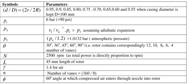
Table 1: Input Parameters
Symbols Parameters
( /
d D
)
(2 / 2 )
r
R
0.95, 0.9, 0.85, 0.80, 0.75 , 0.70, 0.65,0.60 and 0.55 when casing diameter is kept D=100 mm1
p
6 bar (=90 psi)4
p
1
/
4.
1v v
p
>p
5 assuming adiabatic expansion5
p
(
p
4/ 1.2)
>1.0132 bar ( atmospheric pressure)30o, 36o, 45o, 60o, 90o (i.e. rotor contains correspondingly 12, 10, 8, 6, 4 number of vanes)
N
2500 rpm (as total power is directly proportion to rpm)L
45 mm length of rotor1.4 for air
n
Number of vanes = (360 / θ)60o angle at which compressed air enters through nozzle into rotor
5. RESULTS AND DISCUSSION
Based on the variousinput parameters listed in Table-1 and using mathematical model, the effects of different rotor to casing diameters ratios with respect to different vane angles at speed of rotation 2500 rpm and injection pressure 6 bar, the expansion work, exit flow work and total work output from air turbine are studied. Here the injection angle of the air turbine is considered to be constant at 60o as it was found to develop optimum shaft output in earlier studies. The results obtained have been plotted in Figs.4 to 8, for the rotor to casing diameter ratio (d/D), varying as 0.95, 0.90, 0.85, 0.80, 0.75, 0.65, 0.60 and 0.55, at different vane angles of 30o, 36o, 45o, 60o, 90o and at constant injection angle of 60o and injection pressures of 90 psi at the speed of rotation 2500 rpm.
Fig. 4 shows that the variation of shaft power due to expansion becomes maximum and ranging from:
i) 0.71 kW-2.67 kW when rotor to casing diameter ratios are from 0.95-0.80 and vane angle is 30o (Vane nos. 12).
ii) 3.23 kW-3.75 kW when rotor to casing diameter ratios are from 0.75-0.70 and vane angle is 36o (Vane nos. 10) and
iii) 4.21 kW-4.95 kW when rotor to casing diameter ratios are from 0.65-0.55 and vane angle is 45o (Vane nos. 8).
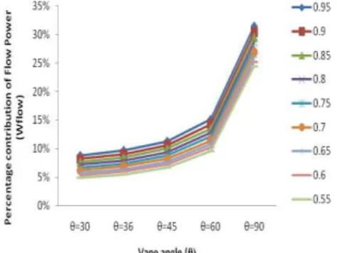
Fig. 5 shows that the shaft power due to exit flow work is lowest ranging from 0.06kW – 0.24 kW at vane angles 30o (Vane nos. 12) and largest ranging from 0.1kW – 0.64 kW at vane angles 90o (Vanes nos. 4) for all rotor to casing diameter ratio 0.95 to 0.55.
Fig. 6 shows that percentage contribution of expansion power is highest ranging from 95.1% to 91.2%, at vane angle 30o (Vane nos. 12) and lowest ranging from 68.6% -75.6%, at vane angle 90o (Vane nos. 4).
Fig. 4 Expansion power versus vane angles with
respect to rotor / casing diameter (d/D) ratio when D= 100 mm
Fig.5 Exit flow power versus vane angles with respect to rotor / casing diameter (d/D) ratio when D= 100 mm
Fig. 6 Percentage contribution of expansion power versus vane angles with respect to rotor / casing diameter (d/D) ratio when D= 100 mm
Fig. 7 Percentage contribution of exit flow power versus vane angles with respect to rotor / casing diameter (d/D) ratio when D=100 mm
Fig. 8 Total power output versus vane angles with respect to rotor / casing diameter (d/D) ratio when D= 100 mm
6. CONCLUSIONS
The results obtained from the above investigation based on input parameters such as injection pressure, injection angle and speed of rotation are kept 6 bar, 60o and 2500 rpm respectively, following conclusions are drawn:
There exists an optimal value of rotor/casing diameter ratio (approx. 0.65 to 0.55) for the considered air turbine for vane angle 45o (8 vanes). This optimal value of rotor/casing diameter ratio offers the maximum expansion power from 4.5 kW to 5.31 kW at injection air pressures 6 bar.
The exit flow power due to steady flow is seen to be maximum and increasing from 0.24 kW to 0.64 kW at rotor / casing ratio 0.55.
Total output power from the air turbine is seen to be maximum for the higher injection air pressure and there exists an optimum value of rotor/casing diameter ratio for injection pressure 6 bar, speed of rotation 2500 rpm and at a particular vane angle. The maximum total power ranges from:
o 0.78 kW to 2.87 kW when rotor to casing diameter ratios are of 0.95-0.80 and vane angle is 30o (rotor vanes are 12 nos.).
o 3.5 kW to 4.0 kW when rotor to casing diameter ratios are of 0.75-0.70 and vane angle is 36o (rotor vanes are 10 nos.) and
o 4.5 kW to 5.3 kW when rotor to casing diameter ratios are 0.65 to 0.55, and vane angle is 45o (rotor vanes are 8 nos.).
Thus optimum shaft power output of a novel vaned type air turbine is obtained when the design parameters for rotor to casing diameter (d/D) ratios are kept between 0.65 to 0.55 and vane angle is of 45o or rotor vanes are 8 nos., as it has vital role for the shaft output.
NOMENCLATURE
d
:diameter of rotor (2r) in meterD :diameter of outer (2R) cylinder in
meter
L
:length of rotor having vanes in metern
: no. of vanes = (360/θ)N
: no. of revolution per minutep
: pressure in bar1
,
1p v
: pressure and volume respectively at which air strike the Turbine,4
,
4p v
: pressure and volume respectively at which maximum expansion of air takes place,5
p
: pressure at which turbine releasesthe air to atmosphere.
v
: volume in cumw
: theoretical work output in (J) JoulesW
: theoretical power output (W) Watts1i
X
: variable extended lengths of vane at point 12i
X : variable extended lengths of vane at point
2
Subscripts
1, 2...4, 5 : subscripts – indicates the positions of vanes in casing
exp : expansion min : minimum max : maximum Greek symbols
: angle BOF (see Fig.3)
1 : angle LOF (=180 - ) (see Fig.3) 2 : angle KOF (=180 - - ) (see Fig.3)
: angle BAF (see Fig.3) : 1.4 for air
: angle between 2-vanes (BOH) (see Fig.3) : angle at which compressed air enters into rotor through nozzle
d : eccentricity (R-r)
[3] Singh B.R. and Singh Onkar, 2007, Use of Non-Conventional Energy for Sustainability to Fossil Fuel, National Conference on Recent Trend
on Mechanical Engineering, RAME-2007, held on 28-29th March'2007 at Baba Sahab Dr. Bhim Rao Ambedkar College of Agricultural
Engineering and Technology, Etawah-Proceedings pp 130-136.
[4] Singh B.R. and Singh Onkar, 2007, Uses of Wind Power as a Non-Conventional / Renewable Energy for Sustainability, National Conference
on State of Art Technology in Mechanical Engineering, STEM-2007, held on October 29-31, 2007 at College of Technology, G.B. Pant
University, Pant Nagar, UP-Proceedings pp 503-515.
[5] Honton E. J., 2004, Hydrogen Fuel Cell Car, presented at 15th Annual US Conference and Hydrogen Expo, April’2004, USA.
[6] Rose Robert and William J. Vincent, 2004, Fuel Cell Vehicle World Survey 2003, Breakthrough Technologies Institute, February’ 2004, Washington, D.C.
[7] Singh B.R. and Singh Onkar, 2006, Necessity and Potential for Bio-Diesel Use in India, International Conference on Bio-Fuel Vision-2015,
October’13th -15th, 2006 at Bikaner, India- Proceedings pp 71-89.
[8] Singh B.R. and Singh Onkar, 2006, Study of Compressed Air as an alternative to fossil fuel for Automobile Engines, International Conference
on Challenges and Strategies for Sustainable Energy and Environment- held on 10-11th June'2006 at UPTU, Lucknow, UP-Proceedings pp
179-191.
[9] Singh B.R. and Singh Onkar, 2008, A Study on Sustainable Energy Sources and its Conversion Systems towards Development of an Efficient Zero Pollution Novel Turbine to be used as Prime-mover to the Light Vehicle, 2008 ASME InternationalMechanical Engineering Congress
and Exposition, held on October 31-November 6, 2008 at Boston, Massachusetts, USA- Paper No. IMECE -2008 -66803.
[10] Negre Guy and Negre Cyril, 2004, Compressed Air - The Most Sustainable Energy Carrier for Community Vehicles, Speech in front of assembly at Kultur gathered for Fuel Cells World, Tuesday 29th June ’2004.
[11] Saint Hilaire G., Saint Hilaire R. and Saint Hilaire, Y., 2005, Quasiturbine zero pollution car using gasoline. Festival at Le Lundi, Montreal
Gazette, 26 September 2005.
[12] Singh B.R. and Singh Onkar, 2008, Development of a vaned type novel Air Turbine, International Journal of Mechanical Engineering Science (The manuscript was received on 21st December 2007 and was accepted after revision for publication on 03rd June 2008), International Journal
of IMechE Vol. 222 Part C, pp 1419-1426.
[13] Knowlen C., Bruckner A. P., Mattick A.T. and Hertzberg A., 1998, High Efficiency Energy Conversion Systems for Liquid Nitrogen Automobiles, Society of Automotive Engineers, Inc., AIAA 98-1898.
[14] Fuglsang P., Bak C. and Gunna M., 2004, Design and verification of the Ris0-B1 Airfoil-family for Wind Turbines, Journal of Solar Energy Engg., ASME- Nov’2004, Vol.126 pp 1002-1008.
[15] Gorla R. and Reddy, S., 2005, Probabilistic Heat Transfer and Structural Analysis of Turbine Blade, IJTJE, Vol. 22, pp 1- 11.
[16] Selig Michel S. and Bryan D. McGranahan, 2004, Wind Tunnel Aerodynamics Tests of Six Airfoils for use on Small Wind Turbines, Journal
of Solar Energy Engg., ASME-Nov’2004, Vol.126, pp986-1000.
[17] Schreck S. and Robinson M., 2004, Tip Speed Ratio Influences on Rationally Augmented Boundary Layer Topology and Aerodynamic Force Generation, Journalof Solar Energy Engg., ASME-Nov’ 2004-Vol.126 pp1025-1033.
[18] Singh B.R. and Singh Onkar, 2008, A concept for Development of a Vaned Type Novel Air Turbine, 12th International Symposium on
Transport Phenomena andDynamics of Rotating Machinery - held on February 17-22, 2008 at Pacific Center of Thermal-Fluids Engineering,
Sheraton Mohana Surfrider Hotel Honolulu, Hawaii - Paper No. ISROMAC-12-20046.
[19] Singh B.R. and Singh Onkar, 2008, Energy Storage System to meet Challenges of 21st Century- an Overview, All India Seminar on Energy
Management in Perceptive of Indian Scenario-held on October 17-19, 2008 at Institution of Engineer (India), State Centre, Engineer's
Bhawan, Lucknow-Proceedings Chapter15, pp 157-167.
[20] Singh B.R. and Singh Onkar, 2008, A Study to Optimize the Output of Vaned Type Novel Air Turbine, 4th International Conference on
Energy Research andDevelopment, held on 17-19 November, 2008 at State of Kuwait, Kuwait- Paper No. ICERD - 4 -1353.
[21] Singh B.R. and Singh Onkar, 2008, Parametric Evaluation of Vane Angle on performance of Novel Air Turbine, Journal of Science,
Engineering and Management, SITM , December, 2008,Vol. 2, pp 7-18.
[22] Singh B.R. and Singh Onkar, 2009, Analytical Study on a Vaned Type Novel Air Turbine for Different Conditions of Casing and Rotor Diameters, 2009 ASME International Conference on Energy Sustainability - held on July 17-23, 2009, at San Francisco, California, USA, Paper No. ES -2009 -90207.
[23] Singh B.R. and Singh Onkar, 2009, Applications of Compressed Air as an Alternative Energy to Meet Challenges of 21st Century- Global Warming, International Conference on Engineering Congress on Alternatives Energy Applications: Option or Necessity?, held on 3-5 November, 2009 at State of Kuwait, Kuwait- Paper No. EC2009 Kuwait-1082.
[24] Singh B.R. and Singh Onkar, 2009, Numerical Analysis of Pressure Admission Angle to Vane Angle Ratios on Performance of a Vaned Type Novel Air Turbine, International Journal of Natural Science and Engineering, IJNSE, France, Vol. 1-1-2009, pp 20-27.
[25] Singh B.R. and Singh Onkar, 2009, Theoretical Investigations on Different Casing and Rotor Diameters Ratio to Optimize Shaft Output of a Vaned Type Air Turbine , International Journal of Natural Science and Engineering, IJNSE, France, Vol. 1-1-2009, pp 28-35.
[26] Singh B.R. and Singh Onkar, 2009, Parametric Evaluations of Injection Angles and Vane Angles on Performance of a Vaned Type Novel Air Turbine, International Journal of Mathematical, Physical and Engineering Science, IJMPES, France, Vol. 3-4-2009, pp 226-233.
[27] Singh B.R. and Singh Onkar, 2009, Optimization of Power Output of a Vaned Type Novel Air Turbine With Respect to Different Injection Angles-Under Ideal Adiabatic Expansion, International Journal of Mechanical Engineering, Serials Publications, New Delhi, India, Vol. 2 Number 2, July-December’2009, pp 205-211.
[28] Singh B.R. and Singh Onkar, 2010, Analytical Investigations on Different Air Injection Angles to Optimize Power Output of a Vaned Type Air Turbine, International Journal of Power and Energy (The manuscript was received on 11thJune’ 2009 and was accepted after revision for publication on 07thOctober’ 2009),
Proceedings of IMechE Vol.224 Part A, (In press).
[29] Singh Onkar, 2009, Reciprocating and Rotary Compressor, Applied Thermodynamics, New Age International (P) Ltd., Publishers, New Delhi,