A R C H I V E S
o f
F O U N D R Y E N G I N E E R I N G
Published quarterly as the organ of the Foundry Commission of the Polish Academy of Sciences
ISSN (1897-3310) Volume 10 Issue 4/2010
17 – 22
4/4
Distributions of grain parameters on the
surface of aircraft engine turbine blades
J. Chmiela
a,*, D. Słota
b, S. Roskosz
ca
Department of Materials Science, University of Silesia, ul. Śnieżna 2, PL-41–200 Sosnowiec
b
Institute of Mathematics, Silesian University of Technology, ul. Kaszubska 23, PL-44–100 Gliwice
c
Department of Materials Science and Metallurgy, ul. Krasińskiego 8, PL- 40-019 Katowice
*Corresponding author. E-mail address: [email protected] Received 01.07.2010; accepted in revised form 01.09.2010
Abstract
In the quality assurance system for components cast using the lost wax method, the object of evaluation is the grain size on the surface of the casting. This paper describes a new method for evaluating the primary grain parameters on the surface of aircraft engine turbine blades. Effectiveness of the method has been tested on two macrostructures distinguished by a high degree of diversity in the grain size. The grounds for evaluating the grain parameters consist of geometric measurement of the turbine blade using a laser profilometer and of approximation of the measurement results using a polynomial of a proper degree. The so obtained analytical non-planar surface serves as a reference point for an assessment of the parameters of grains observed on the real blade surface of a variable curvature. The aspects subjected to evaluation included: the grain areas, shape and elongation coefficients of grains on a non-planar surface of the blade airfoil, using measurements taken on a perpendicular projection by means of a stereoscopic microscope and image analysis methods, and by making calculations using the Mathematica® package.
Keywords: Turbine blades, Grain size, Shape coefficient, Elongation coefficient
1. Introduction
Nickel based superalloys castings are produced by investment casting methods which are constantly improved [1]. Nickel superalloys are used for critical elements of the aircraft engines
(so called „Flight safety parts” - FSP). They are subject of
exceptional requirements in the production and control respects. These elements have to fulfil a lot of requirements of the consumer standards dealing with the chemical composition and microstructure – and first of all the grain size, the microstructure of matrix, the type and relative volume of carbides, porosity and the surface roughness [2-5]. Properties of casted blades made of
nickel based superalloys are determined by porosity, grains size and orientation, morphology and spacing between precipitates of
γ’ phase, carbide particles and the microstructure of matrix [6-9]. In polycrystalline blades of aircraft engine turbines, the size and shape of the grain constitutes one of the most significant quality control criteria of the casts made. In industrial practice, the macrostructure of the airfoil and the blade root is evaluated in terms of the presence of equiaxed, columnar and frozen grains. The grain size has a significant influence on the mechanical properties, creep resistance as well as heat- and high-temperature creep resistance of the blades [10-14].
measuring the grain size on a non-planar surface of the blade airfoil, on the basis of its perpendicular projection [15, 16].
2. Materials
The research material consisted of 2 polycrystalline blades made of IN-100 nickel-based superalloy through investment
casting at WSK “PZL Rzeszów” S.A.
3. Methodology
To detect the presence of primary grains in the investigated superalloys, the airfoil surfaces were etched in a reagent of the following chemical composition: 18 g/dm3 HNO3, 280-320 g/dm3
HCl, 151-173 g/dm3 FeCl3 (anhydrous) and 110 ml/dm 3
H2O.
Before etching, the blade must be degreased; the etching time is 5 seconds.
On the surface of blade made of IN-100 – test 1, there are the following zones: large equiaxed grains on the airfoil; on the airfoil edge, there is a very wide zone of chilled crystals and a wide zone of columnar crystals. Grains of a very large size prevail on the blade root. Due to their inadmissible grain size, a too large chill zone and a too large columnar zone the macrostructure is improper (Fig. 1).
Fig. 1. Macrostructure of blade made of IN-100 – test 1
Blade made of IN-100 - test 2 are uniform throughout their surface in terms of the macrostructure. On both, two roots and the blade airfoil, only equiaxed grains are present (Fig. 2).
Fig. 2. Macrostructure of blade made of IN-100 – test 2
To obtain an image of the airfoil projection, a stereoscopic microscope, Olympus SZX-9, was used. Images were recorded in polarized light at magnification of 10x – 25x. The initial images were then transformed into binary images revealing using the grain boundary lattice using the MetIlo program (Fig. 3).
The measurement of the grain size distribution over the non-planar blade surface requires taking the following steps:
1.Determining the coordinates of grain boundaries’ points – the
input file contains an image of grain boundaries (Fig. 4), which serves as a basis for determining the coordinates of the points being the boundaries of the grains on a flat projection;
2.Measuring the grain size and determining the grain shape and
elongation coefficients, followed by determining the
distributions of these parameters on a perpendicular projection.
Fig. 3. Grain boundaries of blade made of IN-100 – test 2
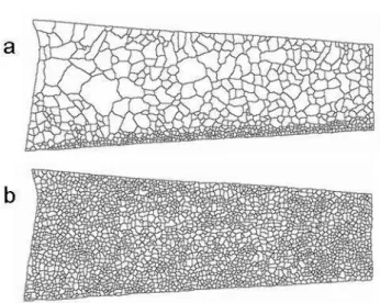
Fig. 4. Grain boundaries of blade in the input file: (a) IN-100 test 1, (b) IN-100 test 2
1.Performing geometric measurements of the blade airfoil using a laser profilometer, NJHP Stone (nanoJura High Precision Surface Metrology System), and approximation of the measurement results with a third degree polynomial.
3.Calculations of the parameters characterizing grains on the non-planar surface (3D). The structure of grain boundaries reconstructed on the analytical surface of the blade provides a foundation for numerical calculations of the grain areas, their circumferences and shape and elongation coefficients.
Fig. 5. Grain boundaries of blade in the input file: (a) IN-100 test 1, (b) IN-100 test 2
4. Results
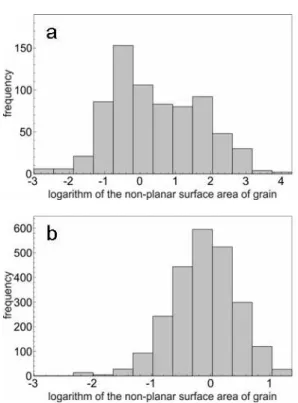
The results of calculations of the areas of non-planar grain surfaces and the grain areas on the projection plane for correct and incorrect macrostructures are presented as distributions with a logarithmic width of classes in Figs. 6 and 7, respectively. 7. Parameters of the grain size distributions in 3D and 2D spaces are presented in Table 1. A supplementary evaluation of the grain size consists of a calculation of the shape and elongation coefficients. The results of the calculations are presented as distributions these values in Figures 8, 9, 10 and 11, respectively, while statistical parameters are shown in Tables 2 and 3.
Table 1.
The parameters of the grain size spatial distributions on a perpendicular projection (2D) and non-planar surface (3D)
Minimal grain area
[mm2]
Maximal grain area [mm2]
Average grain area
[mm2]
Standard deviation [mm2]
Variability coefficient
[%] IN-100 improper macrostructure
2D 0.05 70.29 3.09 5.04 163
3D 0.05 72.66 3.43 5.46 159
IN-100 proper macrostructure
2D 0.05 3.80 0.93 0.50 54
3D 0.05 3.94 1.03 0.56 54
Fig. 6. Grain size distribution on a perpendicular projection: (a) – for incorrect macrostructure;
(b) – for correct macrostructure
Fig. 7. Grain size distribution on a non-planar surface (3D): (a) – for incorrect macrostructure;
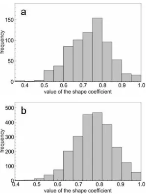
Fig. 8. Distribution of the grain shape coefficient on a perpendicular projection: (a) – incorrect macrostructure;
(b) – correct macrostructure
Fig. 9. Distribution of the grain shape coefficient on a non-planar surface (3D): (a) – incorrect macrostructure;
(b) – correct macrostructure
Table 2.
Distribution parameters of the grain shape coefficient on a perpendicular projection (2D) and non-planar surface (3D)
Minimal shape coefficient
Maximal shape coefficient
Average shape coefficient
Standard deviation
Variability coefficient
[%] IN-100 improper macrostructure
2D 0.36 1.0 0.73 0.10 14
3D 0.36 1.0 0.73 0.10 14
IN-100 proper macrostructure
2D 0.41 1.0 0.77 0.92 12
3D 0.41 1.0 0.77 0.92 12
Table 3.
Distribution parameters of the grain elongation coefficient on a perpendicular projection (2D) and non-planar surface (3D)
Minimal elongation coefficient
Maximal elongation coefficient
Average elongation coefficient
Standard deviation
Variability coefficient
[%] IN-100 improper macrostructure
2D 1.0 3.71 1.50 0.35 23
3D 1.0 3.87 1.50 0.36 24
IN-100 proper macrostructure
2D 1.0 3.75 1.46 0.30 21
3D 1.0 3.65 1.46 0.30 21
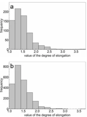
Fig. 10. Distribution of the grain elongation coefficient on a perpendicular projection: (a) – incorrect macrostructure;
Fig. 11. Distribution of the grain elongation coefficient on a non-planar surface (3D): (a) – incorrect macrostructure; (b) – correct macrostructure
All calculations were performed using the package Mathematica, Wolfram Research Incompany.
5. Discussion of results
The new method of evaluation of the stereological parameters of grains on a non-planar surface and on a projection plane has been used for a quantitative analysis of considerably varying macrostructures. The quantitative analysis is made with respect to the grain area distributions and the grain shape and elongation coefficients.
The incorrect macrostructure is distinguished by very significant differences in the grain size, which is reflected in the quantitative analysis. The grain area distributions in the projection plane (Fig. 6) and of the grains with a non-planar surface (Fig. 7) are of a bimodal nature and the differences in the assessment of the average values and standard deviations (Table 1) do not exceed 12%. The quantitative evaluation is supplemented with distributions of the grain shape coefficient (Fig. 8 and 9) and elongation coefficient (Fig. 10 and Fig. 11). These distribution parameters juxtaposed in Tables 2 and 3 show high coincidence of the values calculated.
The quantitative analysis of the grain area carried out for the correct macrostructure yields distributions (Fig. 6 and Fig. 7) of a log-normal nature. The grain size distribution parameters for the grains with a non-planar surface and for the grains in the plane of projection show high coincidence (Table 1). The diversity in the mean values in 2D and 3D spaces is conditional on the grain area
size and grain distribution on the surface of a blade with a variable curvature. The distribution parameters of the shape coefficient (Fig. 8 and Fig. 9) presented in Table 2 and Table 3 and 9) and of the grain elongation coefficient (Fig. 10 and Fig. 11) show high convergence of the values calculated for both, the 2D and 3D space.
While taking account of the complex geometry of blades with a variable curvature and the extreme diversity of the macrostructures analysed, the results of the quantitative evaluation of characteristic parameters of grains with a non-planar surface and grains in the projection plane show high coincidence, which testifies to effectiveness of the method applied.
6. Conclusions
The new method of evaluation of the characteristic parameters of grains with a non-planar surface and grains on a projection plane is effective and can be used for an analysis of any macrostructure of the blade of an aircraft engine turbine.
Any possible constraints in using the new method are conditional on the accuracy of approximation of the geometrical measurement results for the blade.
Acknowledgements
The study has been performed under an ordered research project no. PBZ-MNiSW–03/I/2007/4 funded by the Ministry of Science and Higher Education.
References
[1] S. Jones, C. Yuan, Advances in shell moulding for
investment casting, Journal of Materials Processing Technology 135 (2003) 258–265.
[2] H.S. Whitesell, R.A. Overfelt, Influence of solidification variables on the microstructure, macrosegregation, and porosity of directionally solidified Mar-M247, Materials Science and Engineering A318 (2001) 264–276.
[3] S.A.M. Rezavand, A.H. Behravesh, An experimental
investigation on dimensional stability of injected wax patterns of gas turbine blades, Journal of Materials Processing Technology 182 (2007) 580–587.
[4] Seong-Moon Seo, In-Soo Kima, Chang-Yong Jo, Keisaku
Ogi, Grain structure prediction of Ni-base superalloy castings using the cellular automaton-finite element method, Materials Science and Engineering A 449–451 (2007) 713– 716.
[5] X.L. Yang, H.B. Dong, W. Wang, P.D. Lee, Microscale simulation of stray grain formation in investment cast turbine blades, Materials Science and Engineering A 386 (2004) 129–139.
[7] M. Zielińska, J. Sieniawski, M. Poręba, Microstructure and mechanical properties of high temperature creep resisting
superalloy René 77 modified CoAl2O4, Archives of
Materials Science and Engineering 28 (2007) 629-632.
[8] D. Cai, L. Xiong, W. Liu, G. Sun, M. Yao, Development of
processing maps for a Ni-based superalloy, Materials Characterization 58 (2007) 941–946
.
[9] Roskosz S., Staszewski M., Cwajna J. A complex procedure
for describing porosity in precision cast element sof aircraft engines made of MAR-M 247 and MAR-M 509 superalloys, Materials Characterization 56 (2006) 405–413.
[10]C.H. Sims, N. Stoloff, W.Hagel, Superalloys II: High temperature materials for aerospace and industrial power. Wiley-Interscience Publication, New York, 1987.
[11]X. Xue, L. Xu, Numerical simulation and prediction of solidification structure and mechanical property of a superalloy turbine blade. Materials Science and Engineering A 499 (2009) 69–73.
[12]C. Barbosa, J.L. Nascimento, I.M. Caminha, I.C. Abud, Microstructural aspects of the failure analysis of nickel base superalloys components. Engineering Failure Analysis 12 (2005) 348–361.
[13]S. Roskosz, Relationship between mould’s technology and structure of investment cast nickel based superalloys.
Inżynieria Materiałowa 4 (2008) 375-379.
[14]S. Roskosz, J. Adamiec, Methodology of quantitative
evaluation of porosity, dendrite arm spacing and grain size in directionally solidified blades made of CMSX-6 nickel alloy. Materials Characterization 60 (2009) 1120-1126.
[15]J. Chmiela, D. Słota, J. Cwajna, S. Roskosz, A method for
evaluation of the size of a grain on non-planar surfaces.
Inżynieria Materiałowa 3 (2010), 175, 681 – 685.