SRef-ID: 1607-7946/npg/2004-11-197
Nonlinear Processes
in Geophysics
© European Geosciences Union 2004
Crossing a narrow-in-altitude turbulent auroral acceleration region
R. Pottelette1, R. A. Treumann2,3,*, and E. Georgescu3
1Centre d’ ´Etude des Environnements Terrestre et Plan´etaires, CNRS, 4 av. de Neptune, F-94107 St. Maur des Foss´es, France 2Centre for Interdisciplinary Plasma Science, Max-Planck-Institute for extraterrestrial Physics, P.O.Box 1312, D-85741 Garching, Germany
3Max-Planck-Institute for extraterrestrial Physics, P.O.Box 1312, D-85741 Garching, Germany *Also at Department of Physics and Astronomy, Dartmouth College, Hanover, NH 03755, USA
Received: 21 October 2003 – Revised: 16 December 2003 – Accepted: 17 December 2003 – Published: 14 April 2004 Part of Special Issue “International Workshops on Nonlinear Waves and Chaos in Space Plasmas”
Abstract. We report on the in situ identification of a nar-row electrostatic acceleration layer (electrostatic shock) con-taining intense plasma turbulence in the upward current re-gion, and its effect on auroral particles. Wave turbulence recorded in the center of the layer differs in character from that recorded above and beneath. It is concluded that the shock is sustained by different nonlinear waves which, at each level, act on the particles in such a way to produce a net upward directed electric field. The main power is in the ion acoustic range. We point out that anomalous resistivities are incapable of locally generating the observed parallel po-tential drop.
1 Introduction
The origin of bright aurorae is understood to lie in the pres-ence of mildly energetic electrons in the keV range that are accelerated towards the ionosphere by upward pointing elec-tric fields (Block and F¨althammar, 1990; Bostr¨om et al., 1988). In contrast, black aurorae are attributed to the upward acceleration of ionospheric electrons by downward electric fields (Marklund et al., 1997; Marklund et al., 2001). In the recent past, measurements in situ the upward (Mozer and Hull, 2001; Bostr¨om, 1992a, b) and downward (Carlson et al., 1998b; Ergun et al., 1998; McFaden et al., 2003) auro-ral current regions of the Earth’s auroauro-ral magnetosphere pro-vided ample evidence for this kind of acceleration. The cor-responding upward auroral electric fields in the upward cur-rent region accelerate the ionospheric ion component out into the magnetosphere to become an upward narrow-angle field-aligned ion beam. At the same time the auroral electrons assume a more ring like velocity distribution as predicted by simple adiabatic models (Chiu and Schulz, 1978) of particle motion in the converging magnetic mirror geometry of the Earth’s magnetic field and the electric potentials. Models of Correspondence to:R. Pottelette
(raymond.pottelette@cetp.ipsl.fr)
the acceleration potential region range from large-scale dou-ble layers to turbulent microscopic electric wave structures. Magnetic field-aligned accelerating electric potentials in the upward current region have also been inferred from the in-terpretation of remotely detected auroral kilometric radiation (AKR) fine structure events (Gurnett and Anderson, 1981; Pottelette et al., 2001). The FAST spacecraft, with its high time resolution instrumentation – regarding both wave and particle distributions – and high telemetry rate (Carlson et al., 1998a; Pfaff et al., 2001), has provided new details con-cerning the plasma processes occurring in the auroral accel-eration region.
2 Observations
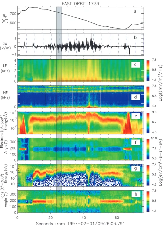
A textbook example of the particle and field signatures dur-ing a FAST spacecraft crossdur-ing of the up- and downward ionospheric current system is given in Fig. 1. These data are derived from one particular orbit which has been extensively studied previously (Elphic et al., 1998; Chaston et al., 2002). The dominant feature is seen in panel (e), where two brief low energy (<few keV) upward electron flux bursts at sec-ond 3 and secsec-ond 68 frame a broad energetic (∼keV) down-ward “inverted-V” electron event (traditionally called so be-cause of its3-like signature in the electron energy spectra) which lasts for 55 s from second 8 to second 63. The electron angle of flow with respect to the magnetic field is shown in panel (f) with 180◦for upward and 0◦(360◦) for downward directions.
a
b
c
d
e
f
g
h
2 3 4
2 3 4
δE
LF
HF
Elec
tr
ons
1
Fig. 1.Plasma measurements during a FAST spacecraft passage through an active auroral current system. The shaded stripe is analyzed in detail in the present Letter.(a): East-West magnetic field component resulting from the magnetic field-aligned currents carried by electrons and flowing in the auroral region during auroral activity. Positive slopes are caused by currents flowing from the magnetosphere downward into the ionosphere, negative slopes are signatures of upward currents.(b): Electric wave field. Note the high activity in the upward current region. (c): Low frequency spectrum of electric waves. The black line at∼200 Hz is the ion cyclotron frequencyfci. Broadband noise
and ion cyclotron harmonics appear in the upward current region. (d): High frequency electric spectrum. The black line at∼350 kHz is the electron cyclotron frequencyfce. At higher frequencies 3 auroral kilometric radiation bands appear. Higher frequency implies lower
altitude above ground. Emission belowfceindicates closeness to the radiation source and acceleration region. (e): Electron energy-flux
10
1
1
1
10
10
Ions upward
P
a
rticle Ener
gy [k
eV
]
0
0
2
1
Time [s after t ]
t
0= UT0 1 Time [s] 2
0.6
0.4
0.2
0.0
T
[k
eV
]
downward
upward
Velocity [km/s]
Parallel Distribution Function (electrons)
28.08-28.63 s
29.34-29.58 s
29.66-29.90 s
high
center
(a)
(b)
(c)
low
downward
upward
Electron Temperature
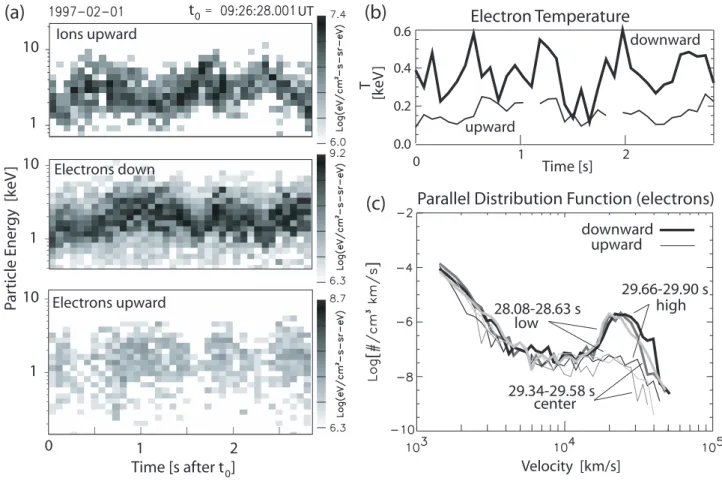
Fig. 2. (a)The ion and electron energy fluxes for the selected 3-s time interval exhibiting the anti-correlation in the energies of the upward ions and downward electrons (upper two panels). The lowest panel shows the upward electron energy flux being correlated with the downward much weaker electron flux. (b)Downward and upward electron temperatures. (c)Downward and upward parallel electron phase space densities (velocity distribution functions) in the three phases of electron energies: high, intermediate and low, corresponding to below, in the center and above the acceleration layer.
It has been demonstrated (Elphic et al., 1998;) that the up-ward current is indeed closed by the two downup-ward currents such that a closed auroral current system is formed. Panel (b) shows the waveform (high-pass filtered above a few Hertz) which illustrates the strong electric activity in the upward current region (note that a direct measurement of the par-allel component of a dc electric field present in the accel-eration region is usually questionable), and panels (c) and (d) give an impression of the low and high frequency wave activity. In panel (d) the emission bands above frequency f ∼350 kHz are events of auroral kilometric radiation, the strong radio signature of substorm activity. The horizontal line in this panel (d) is the electron cyclotron frequencyfce. When the frequency of AKR is close to or belowfce, this is conventionally taken as indication of the spacecraft being right in the radiation source region which is also the site of particle acceleration. The presence of several distinct emis-sion bands indicates that several such acceleration zones may exist simultaneously at different altitudes.
Figure 1 suggests that spatially and temporarily the accel-eration takes place at the two ends of the “inverted-V” re-gion and proceeds in the very short time of 1–2 s. Inside
the “inverted-V” the parallel ion beam energy is fluctuating but its mean energy stays about constant, implying that the spacecraft is right in the acceleration zone and a substan-tial part of the electric acceleration potensubstan-tial is located below spacecraft orbit. Similar considerations apply to the parallel electron energy. However, closer inspection shows that the parallel energies of maximum ion and electron flux oscillate around their averages at a slow though irregular frequency.
Figure 2a shows the high resolution parallel ion and elec-tron fluxes of the selected 3-s time interval measured in an opening angle of∼20◦. The upper two panels visualize a
5 4 3 2 2 3 0 -1
4 0 -1
5
Electric Potential and Field Structure
E
||E
||Space craft Path
Electron beam
Ion beam electrons
Accelerated
ions Accelerated
B
B
~ 10 km
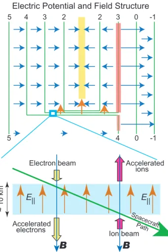
Fig. 3.Model of the electric potential structure, electric field (top) and the passage across the acceleration layer (bottom) which is only a small part (blue box) of the potential structure. Numbers on the lines indicate the hypothetical linearly increasing electric potential which mostly follows the magnetic lines of force. Blue arrows are perpendicular electric fields. The yellow bar is a hypothetical neg-ative charge layer imposed by a converging convection. The red bar corresponds to diverging convection and a positive charge layer. Upward orange arrows indicate the upward electric field in the ac-celeration layer. The length of the arrows indicates the strength of the electric field. They increase towards the negative charge layer which is reflected by the slow increase in ion energy during the “inverted-V” event (Fig. 1). Note that these “charge layers” have not been inferred from the measurements as such measurements are impossible. They have been schematically introduced in order to complete the diverging or converging transverse electric fields and flows.
combination of acceleration in an electric potential field and scattering by the mirror force in a converging magnetic ge-ometry.
In Fig. 2b we plot the downward and upward electron tem-peratures. The downward electrons are about a factor of two hotter than the upward electrons while fluctuating strongly, depending on their phases, with highest temperatures in the intermediate phases between high and low electron energies. Finally, Fig. 2c shows the parallel phase space densities of upward and downward electrons in the high and low
elec-tron energy phases as well as in the intermediate steep en-ergy gradient phase (signified as “center”). The downward phase space distributions exhibit well expressed beams. The upward distribution in the high energy phase is plateaued out which is an indication of a nearly isotropic ring distribution and going on wave-particle interaction.
Quantitatively, the energization of the downward electrons and upward ions from their respective low to high energy lev-els is of the same order of magnitude. For instance, taking the transition in the ions in Fig. 2a at 1.2–1.8 s, the parallel increase in energy is∼4 keV. This increase is matched by the successive increase in the parallel downward electron energy from 1.8–2.0 s, suggesting that the upward ions and down-ward electrons have successively crossed about the same po-tential difference of ∼4 kV. Since ions and electrons have been accelerated into opposite directions by this potential difference, and the ions are at their maximum energy level at the end of this crossing, the spacecraft must have passed a narrow layer of upward directed electric field from below the layer to above the layer and back to below the layer. Fig-ure 3 shows the inferred electric potential and field structFig-ure and the scenario for the downward passage when the space-craft traverses the layer from above to below. In this case the electrons are initially at low energy while the ions are at max-imum energy. After passage the electrons are at high energy, and the ions are found to be at low energy. In the 0.6 s of the first (upward) crossing FAST has moved just 3 km in hori-zontal distance from south to north on this orbit. In the 0.2 s of the second (downward) crossing its horizontal displace-ment was merely 1 km. Hence, the acceleration layer was either strongly folded in the vertical direction which would only be possible if it is very thin, or it moved up and down around the constant altitude of the spacecraft. Evidence for such motions had been obtained earlier from remote sensing observations of AKR (Pottelette et al., 2003) yielding esti-mated vertical (field-aligned) velocities the order of the ion acoustic speed (between 5–50 km/s) and an estimated width of ∼10 km for the accelerating layer. Panel (d) of Fig. 1 shows strong activity in AKR at frequencies below the local fce, indicating that FAST locally crosses the acceleration re-gion, and a ring distribution in the electron phase space den-sity has been formed. Adopting the higher velocity for the crossing, the width of the layer is∼10 km. A field aligned extension of this order is in agreement with a parallel speed of∼20 km/s in the slow crossing. This scenario is in accord with the appearance of upward electrons in the high electron energy phase which result from scattering in the combined magnetic and electric fields during the electron passage from above the layer to below the layer.
3 Discussion and Conclusions
E [
V/m]
||
0.20
0.30
0.15
0.00
0.05
-0.05
0.00
-0.15
-0.20
-0.30
above layer
center
below layer
0.1 1.0 10
Frequency [kHz]
center above
below
Po
w
er Spec
tral D
ensit
y log [(mV/m ) /Hz]
2
f ci f pe
Ion acoustic structures
0
10
20
30
Time [ms]
(a)
(b)
2.0
0.0
-2.0
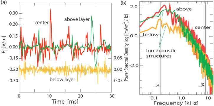
Fig. 4.Magnetic field-aligned electric wave forms(a)and power spectral densities(b)at three positions, above (green), in the center (red), and below (yellow) the acceleration layer for properly selected 30 ms time intervals. The parallel electric wave form above the center of the layer exhibit non-symmetric large-amplitude ion-acoustic solitary structures (ion holes) with net upward directed electric fields. In the center of the layer the electric turbulence is most intense with even stronger asymmetries parallel to the magnetic field but at the same time also much irregular than above the center, containing contributions from higher frequency. Small amplitude nearly unstructured high frequency (electron acoustic) turbulence is observed below the layer. The power spectral densities are high above the center of the layer, maximizing in the ion-acoustic range (<600 Hz), well above the ion-cyclotron frequency. Highest powers are seen in the center of the layer extending to high frequencies. Below the layer ion-cyclotron harmonics and weak high frequency electron acoustic waves are detected.
spacecraft with respect to this layer is fluctuating so that the spacecraft is sometimes above or below the acceleration re-gion. The particle populations have previously been acceler-ated to an energy of about 1–2 keV below the spacecraft in a layer which FAST had traversed at 8 s (see Fig. 1). A sketch of the scenario is given in Fig. 3. The question arises for the internal structure and the physics of this particular layer. In order to infer about their properties we take advantage of the availability of high-resolution measurements of the wave electric field parallel to the magnetic field. This is the direc-tion where acceleradirec-tion is going on.
Figure 4a shows 30 ms of the parallel electric wave form measured at three locations with respect to the acceleration layer, in the upper part of the layer (indicated as above layer) in the high ion energy/low electron energy phase, beneath the layer in the low ion energy/high electron energy phase, and in the center of the layer at the time of maximum gradient in ion energy. These data refer to the time interval 2.32–2.88 s dur-ing which one observes a parallel ion energy decrease (par-allel electron energy increase) of∼4 keV.
The electric field in all three positions is highly turbulent. There are, however, distinctions. The wave amplitudes are largest in the center of the acceleration layer in the average exceeding the fields above by at least a factor of 2 and be-low by an order of magnitude. Amplitudes reach more than
∼300 mV/m here. The character of the turbulence is rather
ir-regular or chaotic with large non-symmetric structures dom-inating over a highly fluctuating background. It is hard to isolate single solitary structures here, but the positive excur-sions in the field clearly dominate. They correspond to up-ward directed fields in this case which are of the order of a few 100 mV/m and thus quite substantial.
Above the layer the low level of the field is quasi-periodically interrupted by large amplitude non-symmetric
Below the layer the amplitudes of the turbulence are much less (<50 mV/m), and at low frequencies ion-cyclotron waves and harmonics appear.
The electric fluctuation spectra (Fig. 4b) are clearly dom-inated by those in the center of the layer where the maxi-mum is in the ion-acoustic range above the ion cyclotron fre-quency, followed by power law decay of the spectrum, with power-law indexξ ∼–2, up to the plasma frequency where a cut-off is weakly indicated. The main power thus resides in the ion-acoustic modes but is modulated by the separation frequency of the single quasi-solitary structures. The plasma frequency derived from electrostatic analyzer data amounts tofpe≈8 kHz, and the cold (<100 eV) electron population has densityn∼0.06 cm−3yielding a cold plasma frequency offpc∼2 kHz. Thus the high frequency turbulence is in ac-cord with the reasonable assumption (Dubouloz et al., 1993) that electron acoustic turbulence contributes and is excited by the hot electrons in cooperation with the residual cold plasma.
The peak spectral power above the layer is above the ion-cyclotron frequencyfci, maximizing in the frequency range around 300 Hz, typical for the presence of bi-polar ion holes excited in this region. In contrast, below the layer the domi-nant peak is around the ion-cyclotron frequency with indica-tion of higher harmonics, which supports other observaindica-tions (e.g. Chaston et al., 2002) of ion-cyclotron waves in rela-tion to the auroral region. Comparison of these harmonics and the modulation of the spectrum in the center of the layer shows that the modulation is not due to the cyclotron har-monics but must be intrinsic to the generation of the quasi-solitary ion hole structure in the center. At frequency above 600–800 Hz the spectrum merges into a steep power law with indexξ ∼–3, indicating the absence of high frequency tur-bulence above the center of the layer.
Finally, below the layer weak ion cyclotron harmonic ac-tivity is dominant (again in agreement with the findings of Chaston et al., 2002). A second peak in the spectrum is found in the range below 1 kHz until at higher frequency the spec-trum merges into a power law slightly flatter than that in the center and of only weakly reduced intensity. This higher fre-quency turbulence which maximizes aroundfpccan be iden-tified with electron acoustic waves, possibly electron phase space holes generated by the interaction of the downward ac-celerated beam and cool upgoing electrons in the ring distri-bution (Dubouloz et al., 1993). Small scale electron holes produced cannot be resolved but move at faster than ion acoustic speed down with the electron beam along the field. The fastest of them leak out from the acceleration layer into the region below where in the spectrum they contribute to the high frequency peak.
The observe asymmetry in some of the solitary structures (holes) is of the order of∼100 mV/m leading us to conclude that this is marginally enough to explain the observed ac-celeration of electrons and ions. The origin of the acceler-ation layer and the origin of the accelerating parallel elec-tric fieldEk(e.g. Tetreault, 1991) is still under debate,
how-ever. Though the parallel electric fields taken from the
soli-tary hole structures over the whole field aligned extension of the acceleration layer are large enough to explain at least part of the acceleration of the particles, it can not yet be proved unambiguously that their observation is the solution of the parallel auroral acceleration problem.
In this respect we comment on the question whether anomalous resistivity ηan = Ek/jk generated by
instabili-ties of the field-aligned currentjkin the upward current
re-gion, as suggested by several authors (e.g. Kindel and Ken-nel, 1971), could be responsible for the necessary potential drop 18 = −R0LEkds along the magnetic field over the
widthLof the acceleration layer. We can easily demonstrate that the anomalous resistivities required can hardly be pro-duced by any of the known plasma instabilities. Indeed, the field-aligned current density can be obtained from panel (a) of Fig. 1 as jk = 1Bz/µ0vsc1t. With 1Bz ≈100 nT, 1t =20 s, and the spacecraft velocity of vsc ≈5 km/s, the parallel current density isjk≈8×10⁻⁷A/m2, in agreement
with the findings of Elphic et al. (1998). The acceleration potential amounts to18≈(3–4) kV. AssumingL= 10 km, this yields ηan ∼ 4×10⁵/L10Vm/A, a rather high value for the collisionless plasma of the topside ionosphere at al-titude of 3000 km. The resistivity is defined through the anomalous collision frequencyνanasηan =νan/ǫ0ωpe2 , with ωpe = 2π fpe. The observations yieldfpe= 8 kHz corre-sponding to a density of the order ofn∼0.95 cm−3, which gives for the anomalous collision frequency
νan∼0.01n/L10≈104/L10 Hz.
Independent of any reasonable choice for the parallel exten-sion of the acceleration layer long the magnetic field this value for the anomalous collision frequency is huge, of the order of the electron plasma frequency. No reasonable cur-rent or gradient driven plasma instability is known which could provide a collision frequency of this value. In fact, the theoretical ion acoustic collision frequency estimated for the above parameters is by at least four orders of magnitude below the required collision frequency. We may thus con-clude that anomalous resistivities are incapable of generating the required potential drop and thus can be discarded as the agents of the observed particle acceleration in the aurora.
for a large fraction of the acceleration of electrons and ions. Hence a small number of such layers are required only to pro-vide the total “inverted-V” electron energy in bright aurorae. It should be stressed that the observations discussed in the present paper are in good agreement with recent numerical simulation results on generation of holes (Singh et al., 1987; Singh and Khazanov, 2003). In particular, Singh et al. (1987) predicted the main features of panel (e) in Fig. 1 from simu-lations, namely a wide upward current sheet sandwiched be-tween two return current regions. The self-consistent poten-tial structure accelerating the upward and downward acceler-ated electrons and ions was found from 2-D PIC simulations of current sheet equilibrium by varying the width of the up-ward current sheet. In addition, they predicted the different types of turbulence above and in the center of the accelera-tion layer (their Figs. 10 and 13, the contours H, there, show the spiky fields of transient double layers, which contribute to the downward accelerations of electrons and upward ac-celerations of ions).
We note once more that the mechanism of formation of such layers remains essentially unclarified. We believe that the mechanism of formation is closely related to the pres-ence of shear flows, as indicated in Fig. 3. Note that in the present cases shear motions (converging perpendicular electric fields) are highly reasonable to exist in the entire field-aligned potential drop (acceleration) zone as they are required by the potential structure. Ganguli (1997) has shown that the effect of such velocity shear on the low-frequency kinetic Kelvin-Helmholtz instability is very im-portant. Though the Kelvin-Helmholtz instability in the ki-netic regime is strongly Landau damped, a new branch of shear velocity driven instability arises which produces broad-band electric turbulence in the perpendicular direction, with frequency ranging from the ion cyclotron frequencyf∼fci up to∼10fci. This instability is not sensitive to the details of the shear flow. Figure 4 refers to parallel turbulence, how-ever, and thus does not contain contributions of this kind of oscillations.
In conclusion we note that, thanks to the high time reso-lution measurements performed on board the FAST space-craft including both wave and particle distributions, it has been possible to clearly identified the characteristics of the turbulence generated inside a shock structure located in the upward current region. At each level, nonlinear electron and ion acoustic structures appear to play a key role in sustain-ing the shock and producsustain-ing localized small-scale net upward electric fields.
Acknowledgements. The authors thank M. Berthomier, R. Ergun, J. McFadden, and C. Carlson for discussions.
Edited by: G. S. Lakhina
Reviewed by: G. I. Ganguli and another referee
References
Block, L. P. and F¨althammar, C.-G.: The role of magnetic field-aligned electric fields in auroral acceleration, J. Geophys. Res., 95, 5877–5888 , 1990.
Bostr¨om, R.: Voltage drops along auroral magnetic field lines on small and large scale, Phys. Space Plasmas, 15, 37–49 , 1992a. Bostr¨om, R.: Observations of weak double-layers on auroral field
lines, IEEE transactions on plasma science 20, 756–763, 1992b. Bostr¨om, R., Gustafsson, G., Holback, B., Holmgren, G., and Kosk-inen, H.: Characteristics of solitary waves and weak double lay-ers in the magnetospheric plasma, Phys. Rev. Lett., 61, 82–85, 1988.
Carlson, C. W., Pfaff, R. F., and Watzin, J. G.: The Fast Auroral Snapshot (FAST) mission, Geophys. Res. Lett., 25, 2013–2016, 1998a.
Carlson, C. W., McFadden, J. P., Ergun, R. E., et al. : FAST ob-servations in the downward auroral current region: Energetic up-going electron beams, parallel potential drops, and ion heating, Geophys. Res. Lett., 25, 2017–2020, 1998b.
Chaston, C. C., Bonnell, J. W., McFadden, J. P., Ergun, R. E., and Carlson, C. W.: Electromagnetic ion cyclotron waves at proton cyclotron harmonics, J. Geophys. Res., 107, 1–19, 2002. Chiu, Y. T. and Schulz, M.: Self-consistent particle and
par-allel electrostatic field distributions in the magnetospheric-ionospheric auroral region, J. Geophys. Res. 83, 629–642, 1978. Dubouloz, N., Treumann, R. A., and Pottelette, R.: Turbulence gen-erated by a gas of electron-acoustic solitons, J. Geophys. Res., 98, 17 415–17 422, 1993.
Elphic, R. J., Bonnell, J. W., Strangeway, R. J., et al.: The auro-ral current circuit and field-aligned currents observed by FAST, Geophys. Res. Lett., 25, 2033–2036, 1998.
Ergun, R. E., Carlson, C. W., McFadden, J. P., et al.: FAST satel-lite observations of large amplitude solitary structures, Geophys. Res. Lett., 25, 2041–2044, 1998.
Ganguli, G.: Stability of an inhomogeneous transverse plasma flow, Phys. Plasmas, 4, 1544–1551, 1997.
Ganguli, G., Shinkler, S., Gavrishchaka, V., and Scales, W.: Low frequency oscillations in a plasma with spatially variable field-aligned flow, Phys. Plasmas, 9, 2321, 2002.
Gray, P., Hudson, M. K., Lotko, W., and Bergmann, R.: Decay of ion beam driven acoustic waves into ion holes, Geophys. Res. Lett., 18, 1675–1678, 1991.
Gurnett, D. A. and Anderson, R. R.: The kilometric radioemis-sion spectrum: relationship to auroral acceleration processes, in Physics of auroral arc formation, edited by Akasofu, S.-I. and Kan, J. R., AGU, Washington, D.C., Geophys. Monogr. 25, 341– 350, 1981.
Hudson, M. K., Lotko, W., Roth, I., and Witt, E.: Solitary waves and double layers on auroral field lines, J. Geophys. Res., 88, 916–926, 1983.
Marklund, G., Karlsson, T., and Clemmons, J.: On low-altitude par-ticle acceleration and intense electric fields and their relation to black aurora, J. Geophys. Res., 102, 17 509–17 522, 1997. Marklund, G. T., Ivchenko, N., Karlsson, T., et al: Temporal
evo-lution of the electric field accelerating electrons away from the auroral ionosphere, Nature, 414, 724–727, 2001.
Mozer, F. S. and Hull, A.: Origin and geometry of upward parallel electric fields in the auroral acceleration region, J. Geophys. Res., 106, 5763–5778, 2001.
Muschietti, L., Ergun, R. E., Roth, I., and Carlson, C. W.: Phase-space electron holes along magnetic field lines, Geophys. Res. Lett., 26, 1093–1096, 1999.
Pfaff, R., Carlson, C., Watzin, J., et al.: An overview of the Fast Auroral SnapshotT (FAST) satellite, Space Sci. Rev., 98, 1–32, 2001.
Pottelette, R., Treumann, R. A., and Berthomier, M.: Auroral plasma turbulence and the cause of auroral kilometric radiation fine structure, J. Geophys. Res., 106, 8465–8476, 2001. Pottelette, R., Treumann, R. A., Berthomier, M., and Jasperse, J.:
Electrostatic shock properties inferred from AKR fine structure, Nonlin. Proc. Geophys. 10, 87–92, 2003.
Singh, N., Thiemann, H., and Schunk, R. W.: Simulations of auroral plasma processes: Electric fields, waves and particles, Planet. Space Sci., 35, 353–395, 1987.
Singh, N. and Khazanov, G.: Double layers in expanding plasmas and their relevance to the auroral plasma processes, J. Geophys. Res., 108, 8007, COA 8-1-8-16, 2003.
Temerin, M., Cerny, K., Lotko, W., and Mozer, F. S.: Observations of double layers and solitary waves in the auroral plasma, Phys. Rev. Lett., 48, 1175–1179, 1982.
Tetreault, D.: Theory of electric fields in the auroral acceleration region, J. Geophys. Res., 96, 3549–3561, 1991.