ISSN 1546-9239
© 2012 Science Publications
Corresponding Author: Habib Ullah, M., Department of Electrical Electronics and System Engineering, Institute of Space Science (ANGKSA), University Kebangsaan Malaysia, Malaysia
117
Design of Transmitter for CDM Based 2×2 Multiple Input
Multiple Output
Channel Sounder for Multipath Delay Measurement
Habib Ullah, M., M.T. Islam, Mandeep Sing, Rosdiadee Nordin and Badariah Bais
Department of Electrical, Electronic and System Engineering,
Institute of Space Science (ANGKASA), University Kebangsaan Malaysia
Abstract: Problem statement: Multiple Input Multiple Output (MIMO) wireless communication
system is an innovative solution to improve the bandwidth efficiency by exploiting multipath-richness of the propagation environment. The degree of multipath-richness of the channel will determine the capacity gain attainable by MIMO deployment. Approach: Therefore, it is very important to have accurate knowledge of the propagation environment/radio channel before MIMO implement. The radio channel behavior can be anticipated by channel measurement or channel sounding. Code Division Multiplexing (CDM) is one of the channel sounding techniques that allow accurate measurement at the cost of hardware complexity. CDM based channel sounder, requires code with excellent auto-correlation and cross-auto-correlation properties which generally difficult to be achieved simultaneously.
Results: In this study, an efficient transmitter for CDM-based 2×2 MIMO channel sounding technique
with Loosely Synchronous (LS) codes is designed. Simulation results shows that the channel sounding scheme using LS codes gives very good performance for measuring 2×2 MIMO channel behavior. The BPSK transmitter is designed using MATLAB, Verilog and Xilinx system generator blocks.
Conclusion: The whole design is simulated as a single ISE project by using ModelSim simulation tool
and compiled using ISE 9.2. However the proposed design of transmitter using LS code of length 8190 bits can measure multipath delay of minimum 0.13 s and maximum 520 s.
Key words:MIMO, transmitter, channel sounder, CDM, multipath delay
INTRODUCTION
Multiplexing multicarrier communications have become very important for the future communications networks. Numerous researches on antenna technology are ongoing both in industry and academia to provide reliable communication systems (Numan et al., 2010). Recently the demand for both higher data rates and more reliable wireless communications in severe multipath fading is rapidly increasing. In real environment accurate knowledge of the propagation channel is required to process MIMO receiving systems. Thus, the accuracy of MIMO channel measurement is an important issue in many aspects like simulation, system design and performance analysis. A major research focus in this area has been the use of multiple antennas for transmitting and receiving instead of the traditional single antenna systems. It has been proposed that using multiple transmit and receive antennas and associated coding techniques could increase the performance of wireless communication. So far, there has been a lot of theoretical research but
relatively few practical systems have been demonstrated. Knowing the characteristic of the MIMO channel parameters is very important issue to determine performance of the MIMO system.
118 Tbb seconds and uses a receiver with a wide band pass filter, the received signal is then amplified, detected with an envelope detector, acquired and stored. The minimum resolvable delay between multipath components is equal to the probing pulse width Tbb, while the repetition rate TREP determines the maximum unambiguous excess delay that can be resolved (Ullah
et al., 2008; 2009a; 2009b; Ibrahimy et al., 2009) the pulse repetition rate must be fast enough to allow observation of the time-varying response of individual propagation paths, while the time interval between pulses must be long enough to ensure that all multipath signals have decayed between successive pulses. This type of system gives an immediate measurement of the square of the channel impulse response convolved with the probing pulse; however it is subject to interference and noise due to the wide band pass filter required for multipath delay resolution; besides, the transmitted signal must have a high peak-to-mean power ratio to provide adequate detection of weak multipath components. No information about the phases of the multipath components can be obtained in this type of system due to the use of an envelope detector.
The previous schemes for MIMO channel measurement are to Use Time-Division Multiplexing with Synchronized switching (TDMS) based MIMO channel sounder (Choi et al., 2006). Although this technique is cost effective, it has the major drawback that absolute time synchronization and excess time slots are needed. As another approach, Code-Division Multiplexing (CDM) based MIMO channel sounder with low correlation codes was introduced (Choi et al., 2006; Islam et al., 2009a; 2009b; 2010a; 2010b; 2011; Shakib
et al., 2010; Tsoulos, 2006). However, it also has disadvantage that dynamic range is limited by the number of transmit antennas due to none-zero correlation values. In this study an efficient transmitter with Loosely Synchronous (LS) code sequence with optimized Interference Free Window (IFW) for CDM based 2×2.
MATERIALS AND METHODS
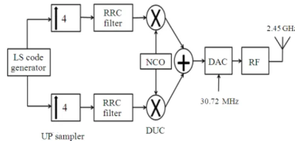
A BPSK Transmitter with LS Code generator is designed using the Sundance FPGA development boards. The proposed design block diagram and explanation is shown in Fig. 1.
LS code generator: Code-Division Multiplexing
(CDM) based MIMO channel sounder with low correlation codes was introduced (Choi et al., 2006). Due to the excellent correlation properties of the Loosely Synchronous Code, it can solve the problem caused in TDMA system. In CDM system it is really challenging to have such code sequence with good auto and cross correlation property at the same time.
Fig. 1: Block diagram of BPSK transmitter
LS codes are defined as the combination of C and S subsequences, a Golay complementary pair, with zeros inserted to avoid overlapping between the two subsequences. If (C0, S0) and (C1, S1) are both Golay pairs of LS codes (Choi and Hanzo, 2002). As a result of inserted zeros, LS codes have features that aperiodic autocorrelation side lobes and cross-correlations are zero within IFW zone. The main purpose of zeros insertion of the LS codes is to avoid the sequences C0 and C1 overlapping with the sequences S0 and S1. Note that it is also necessary to insert enough guard intervals between sequences with length longer than the maximum delay of the multipath channel.
LS code correlation properties: The definitions and
properties of Auto and Cross Correlation Functions (ACF/CCF) of any two codes LSi and LSj (Kim et al., 2008) are given as (Eq. 1):
N 1 N 1
ij i,n j,(n ) mod N i,n j,(n ) mod N
n 0 n 0
ij
R ( ) C C S S
2N , 0, i j 0 , 0, i j 0 , 0 W
− − +τ +τ = =
τ = +
τ = =
= τ = ≠
< τ <
∑
∑
(1)
119 Fig. 2: Simulation result of cross correlation properties
of LS codeset
Fig. 3: Simulation result of auto correlation properties of LS codeset
Fig. 4: The response of RRC filter
Figure 2 and 3 shows the cross correlation of code 1 and code and auto correlation of code 1 respectively. Up sampler increases the sampling rate of the signal. In the proposed design the signal up sampled by 4 before pulse shaping.
Root raised cosine filter: The spectrum of a
rectangular pulse spans infinite frequency. In such instances, the infinite bandwidth associated with a rectangular pulse is not acceptable. The bandwidth of the rectangular pulse can be limited, however, by forcing it to pass through a filter.
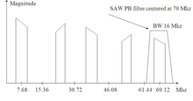
Fig. 5: DAC output spectrum
Table 1: Technical specification of Tx up converter.
Parameter Value
Linear output power -20dBm, average Output power at 1 dB compression 0dBm, minimum RF frequency range 2400-2500 MHz
Gain control 31dB, in 1dB steps
Gain control accuracy ±2dB Maximum
The act of filtering the pulse causes its shape to change from purely rectangular to a smooth contour without sharp edges. Therefore, the act of filtering rectangular data pulses is often referred to as pulse shaping. System Generator tool provides high-level abstractions that are automatically compiled into a netlist code. Mainly in SIMULINK system generator register, multiplier and constant blocks are used to design RRC filter. System Generator block sets allow us to construct bit-accurate and cycle-accurate models of an FPGA circuit in Simulink.
In the proposed transmitter design, Root Raised Cosine (RRC) filter is designed for the purpose of pulse shaping. Figure 4 shows 32 order response of RRC filter. The netlist generations of the RRC filter to create the Verilog code which is compatible for implementation. The specification of the RRC filter; sampling rate is 7.68 MHz, pulse duration 0.13 s and the roll off factor is 0.25.
Digital up converter: In the transmitter design the up
conversion from 70 MHz IF to the 2.4 GHz RF is done in two stages: The first stage converts the 1st IF to 374 MHz and the second stage converts to the 2.4 GHz RF frequency. Numerically Controlled Oscillator (NCO) is used for up conversion. The specification of up converter is given in Table 1.
Digital to analog converter:DAC converts the 16 bit
120 Transmitter up-convert 70 MHz signal to 2.45 GHz and transmit it through Antenna. Amplitude of the output spectrum reduces due to DAC sinc effect.
RESULTS
The proposed BPSK transmitter is designed using MATLAB, Verilog and Xilinx system generator blocks. The whole design is simulated as a single ISE project by using ModelSim simulation tool and compiled using ISE 9.2. The ISE project synthesized as top module Tx_lscode_top Module including two submodule lscode1 and lscode2. The ISE project synthesis report, ModelSim simulation result and RTL illustration of top module and sub modules are included in this section.
Figure 6 presents the Register Transfer Level (RTL) schematic of the designed model. In integrated circuit design, RTL description is a way of describing the operation of a synchronous digital circuit. In RTL design, a circuit's behavior is defined in terms of the flow of signals (or transfer of data) between hardware registers and the logical operations performed on those signals.
For the Verilog Simulation, the ISE 9.2 supports the ModelSim XE III 6.4b Waveform entity simulation methods’ such as using Vector Waveform File (VWF). The RTL schematic view of Top module of proposed transmitter design is illustrated in Fig. 7. The transmitter top module consists of 2 sub-module lscode1 and lscode2. It has 2 input clk and resetn and 16 bit output data_out_scaled. Figure 7 shows the ModelSim simulation result of the transmitter top module.
Figure 8 shows the RTL schematic view of lscode1 sub-module. The lscode1 sub-module consists of counter and memory. Counter has 3 inputs clk, clken and port adr_q; 12 bits output port_q. Figure 9 shows the ModelSim simulation result of the lscode1 sub-module.
The RTL schematic view of lscode2 sub-module is shown in Fig. 10. The lscode2 sub-module consists of one 14-bit input and one bit output counter, two 14-bit input and one-bit output adder and 1 FDR. Counter has 3 inputs clk, clken and port adr_q; 12 bits output port_q. Figure 11 shows the ModelSim simulation result of the lscode2 sub-module.
Fig. 6: RTL view of Transmitter top module
Fig. 7: Simulation result of Tx_lscode_top Module
Fig. 8: RTL view of lscode1 sub-module
Fig. 9: Simulation result of lscode1 Sub-Module
121 Fig. 11: Simulation result of lscode2 Sub-Module
DISCUSSION
Initially, MATLAB has been used, to design the LS code generator and investigate the correlation properties. After required codeset generated with excellent correlation properties, Xilinx system generator blocks used to design the Root Raised Cosine filter for pulse shaping purpose. The proposed design of transmitter was coded in Verilog, compiled and synthesized in ISE 9.2. For Verilog modeling and implementation, the algorithm has to be thought of as a structural, behavioral and physical version of the algorithm. The components of FPGA, input output and device utilization are shown in the summary report.
CONCLUSION
A BPSK Transmitter for 2×2 CDM based channel sounder has been successfully designed, tested and synthesized by using MATLAB, Xilinx ISE and ModelSIM. The necessary code sequence with excellent auto and cross correlation properties also investigated from LS code. The expected correlation properties of LS code are optimized. Two LS code sequences with same code length are chosen as sounding sequence. From two 8190 bits of code sequences with simulated and the length of IFW are 4000 bits. According to the length of IFW the implemented system can measure minimum 1bit duration and maximum 4000 bit duration. After successfully designed the BPSK transmitter it synthesized and verified. The proposed system can measure the delay of minimum 0.13 s and maximum 520 s.
REFERENCES
Choi, B.J. and L. Hanzo, 2002. On the design of LAS spreading codes. Proceedings of the IEEE 56th Vehicular Technology Conference (VTC’02), IEEE Xplore Press, Vancouver, Canada, pp: 2172-2176. DOI: 10.1109/VETECF.2002.1040604
Choi, J.H., H.K. Chung, H. Lee, J. Cha and H. Lee, 2006. Code-division multiplexing based MIMO channel sounder with loosely synchronous codes and Kasami codes. Proceeding of the 64th IEEE Vehicular Technology Conference, Sept. 25-28, pp: 1-5. DOI: 10.1109/VTCF.2006.33
Ibrahimy, M.I., M.A. Hasan and M.H. Ullah, 2009. Design of an automated rail transit system controller: Malaysia perspective. Aus. J. Basic Applied Sci., 3: 3500-3509.
Islam, M.T., M. Moniruzzaman, N. Misran and M.N. Shakib, 2009a. Curve fitting based particle swarm optimization for UWB patch antenna. J. Electromagnetic Waves Appli., 23: 2421-2432. Islam M.T., Shakib M.N. and N. Misran, 2009b.
Multi-slotted microstrip patch antenna for wireless communication. Progress Electromagnetics Rese.
Lett., 10: 11-18. DOI: DOI:
10.2528/PIERL09060704
Islam M.T., M.R.I. Faruque and N. Misran, 2010a. Study of Specific Absorption Rate (SAR) in the human head by metamaterial attachment. IEICE Elect. Express, 7: 240-246. DOI: 10.1587/elex.7.240
Islam, M.T., A.T. Mobashsher and N. Misran, 2010b. Design of microstrip patch antenna using novel U-shaped feeding strip with unequal arm. Elect. Lett., 46: 968-970. DOI: 10.1049/el.2010.0409
Islam M.T., M.W. Numan, N. Misran, M.A.M. Ali and M. Singh, 2011. Hardware implementation of a MIMO decoder using matrix factorization based channel estimation. Frequenz, 65: 79-85. DOI: 10.1515/FREQ.2011.012, /May/2011
Kim, M., S. Kim, H. Lee, H. Lee and H.R. You, 2008. Performance comparison of some codes in code division multiplexing based MIMO channel sounder architecture. Proceedings of 10th International Conference on Advanced Communication Technology, Feb. 17-20, IEEE Xplore Press, Gangwon-Do, pp: 1343-1346. DOI: 10.1109/ICACT.2008.4494013
Numan, M.W., M.T. Islam and N. Misran, 2010. An efficient FPGA-based hardware implementation of MIMO wireless systems. Proceedings of the 7th International Symposium on Communication Systems Networks and Digital Signal Processing, Jul. 21-23, IEEE Xplore Press, Newcastle upon Tyne, pp: 152-156.
122 Tsoulos, G.V., 2006. MIMO System Technology for
Wireless Communications. 1st Edn., CRC/Taylor and Francis, CRC Press, United Kingdom, ISBN: 9780849341908, pp: 378.
Ullah, M.H., A.U. Priantoro and M.J. Uddin, 2008. Design and construction of direct sequence spread spectrum CDMA transmitter and receiver. Proceedings of the 11th International Conference on Computer and Information Technology, Dec. 24-27, IEEE Xplore Press, Khulna, pp: 675-680. DOI: 10.1109/ICCITECHN.2008.4803054
Ullah, M.H., A.U. Priantoro, M.A. Hasan and M.J. Uddin, 2009a. FPGA Implementation of light rail transit fare card controller using VHDL. Eur. J. Sci. Res., 38: 30-40.
Ullah, M.H., M.A. Hasan, M.J. Uddin and A.U. Priantoro, 2009b. VHDL modeling of optimum measurement selection by using genetic algorithm. Aust. J. Basic Applied Sci., 3: 3283-3290.
Ullah, M.H., S.M. Raihan and M.N. Bary, 2011. Performance analysis of power control schemes in CDMA communication system. Proceedings of the 4th International Conference on Mechatronics, May 17-19, IEEE Xplore Press, Kuala Lumpur,
Malaysia, pp: 1-4. DOI: