Fiabilitate si Durabilitate - Fiability & Durability no 2(6)/ 2010
Editura “Academica Brâncuşi” , Târgu Jiu, ISSN 1844 – 640X17
ANALYTICAL MODEL OF CALCULUS FOR INFLUENCE THE
TRANSLATION GUIDE WEAR OVER THE MACHINING ACCURACY
ON THE MACHINE TOOL
Assoc.prof.dr.eng. Ivona PETRE, University Valahia from Targoviste, Lecturer dr. eng. Carmen POPA, University Valahia from Targoviste, Lecturer dr. eng. Dumitru DUMITRU, University Valahia from Targoviste,
Eng. Ciprian MANESCU, University Valahia from Targoviste,
Abstract: The wear of machine tools guides influences favorably to vibrations. As a result of guides wear, the initial trajectory of cutting tools motion will be modified, the generating dimensional accuracy discrepancies and deviations of geometrical shape of the work pieces. As it has already been known, the wear of mobile and rigid guides is determined by many parameters (pressure, velocity, friction length, lubrication, material). The choice of one or another analytic model and/or the experimental model of the wear is depending by the working conditions, assuming that the coupling material is known.The present work’s goal is to establish an analytic model of calculus showing the influence of the translation guides wear over the machining accuracy on machine-tools.
Keywords: accuracy, machine-tools, surface.
1. Introduction
As it has already been known the accuracy of machining each piece depends on a multitude of factors connected to the technological system (the machine tool, the clamping device, the cutting tool etc) [1, 2, 3].
In the present work, the author’s goal is to establish the size and influence only of the wear of the bed the slide guide over the machining accuracy on machine-tools with use on lather. The size of the guide and (longitudinal) slide wear are important to be known because the change of the slide trajectory due to the wear that occurs in time conditions the dimensional deviations and the quality of the machined parts surface.
In order to establish the wear size of the system bed-slide, three distinct situations are being analyzed:
1 – the bed guide only is being worn 2 – the slide guide only is being worn 3 – both guides (bed-slide) are being worn
2.Analytic models establishing the error produced by the bed-slides wear
In order to establish the quantitative influence of the wear process over the machining accuracy on a lathe, the following assumptions are made [2]:
- the curve of the worn profile of the rigid guide U(x) is considered known at a certain moment assessed by the number of the stress cycles;
- the wear on the current stress cycles is neglected compared to the wear produced by all the previous cycles;
- the mobile guide wear U1(l) is so produced that the profile of this guide follows continuously the rigid guide profile; based on this assumption it is admitted that the contact is always of the type according to the appropriate distribution of the normal and tangential stress;
- the mobile guide is set on the rigid one during the displacement so that normal line to the contact surface of the two profiles is unique;
Fiabilitate si Durabilitate - Fiability & Durability no 2(6)/ 2010
Editura “Academica Brâncuşi” , Târgu Jiu, ISSN 1844 – 640X18
Based on these assumptions the wear of the bed and slide guide is established for the 3 situation shown in the first part of the work.
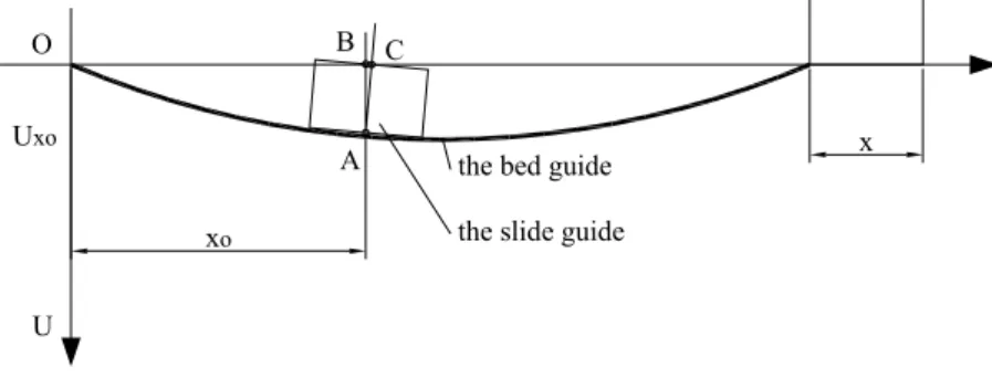
Case 1: the bed guide is being only (fig.1)
xo
x A
B C O
U
the bed guide
the slide guide Uxo
Fig.1.Settlement scheme of the mobile slide on a bed-guide
Taking a point A (xo, Uxo) situated at the middle of the mobile slide. The wear of the bed guide in the considered point is Uxo and the function of the bed guide wear Ux. The deviation of the point A is considered∆1 =AC.
In order to establish, the coordinates of the point C the normal at the bed guide profile in the point A is considered a straight line with the slope m that can be determined based on the wear function Ux.
n mx
y= + (1)
' xM
U / 1
m=− (2)
Where: x n
U 1
U '
x
x =− + and x
U 1 U
n '
x
x +
=
Being the conditions to limit, the co-ordinates of the point C will be yc =0 and x
U U
xc = x 'x + .
The deviation in this case considered:
(
) (
)
( )
adm2 ' x x
2 A c 2 A c
1 = x −x + y −y =U 1+ U ≤∆
∆ (3)
Case 2: the slide guide only is being worn according to a linear variation law (fig.2).
Considering the point B(0,b) situated at the half of the slide with the length l. After a certain period of functioning, as a result of the slide wear, the point B will be displaced in the point B’. In this situation the deviation of the point will be: ∆2 =BB'
In order to make the calculation of this deviation 2 cases can be distinguished: a) the point A is not worn UA =0;
b) the point A is worn by a size that can be established (measured) UA ≠0
a
a
l B(0,b)
B' Slide
Bed
C' M O' O C
A(a,0)
Fiabilitate si Durabilitate - Fiability & Durability no 2(6)/ 2010
Editura “Academica Brâncuşi” , Târgu Jiu, ISSN 1844 – 640X19
• Staring from the equation of the straight line that goes through the points AO’ and following the some argument as in case 1, the deviation of the point B’ will be: - for UA =0⇒ ∆2 =2 a2 +b2 ⋅cosα/2
- for UA ≠0⇒ ∆'2=2 a2 +(b+UA)2 ⋅cosα/2
The size of the angle α depends on the size of the accuracy deviation imposed to the slide:
l U AM MC
tgα= = c (4)
The angle α can be known if the wear of the point C, Us and α <αadm are measured (known).
The allowable size of the angle αadm is a size that can be established from the accuracy conditions imposed by the machine tool on which the slide is installed where:
l A A A l A tg i pp i ra + = = α (5)
where: Ai – the initial deviation that can be accepted as being the maximum allowable deviation prescribed within the accuracy parameters of the machine-tool;
App – the accuracy deviation allowable of the parts machined on the machine tool; Ara – the allowable relative deviation of accuracy;
l – slide length
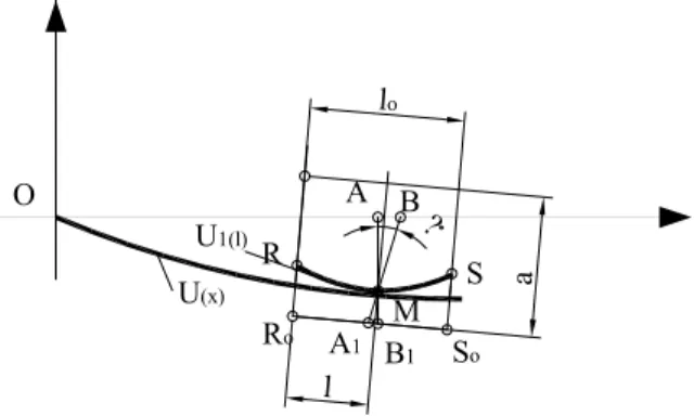
Case 3: booth the mobile slide U1 (l) and the bed U(x) are worn as in figure 3.
A B O l a lo ? M A1 B1
S So Ro R U1(l) U(x)
Fig. 3. Assessment scheme of the changes caused by wear
The straight line at the bed guide in a point is a line having m slope that can be established based on the wear function U (x). Following the some argument as in cases 1 and 2 for a common point M on the bed and slide guide the changes of the co-ordinates of this point will be: 2 M M 1 M 1 M )) x ( ' U ( 1 1 ) l ( U ) x ( U MB AM y + + = + =
∆ (6)
2 M M M 1 1 M )) x ( ' U ( 1 ) x ( ' y ) l ( U sin M A x + ⋅ = γ ⋅ =
∆ (7)
Fiabilitate si Durabilitate - Fiability & Durability no 2(6)/ 2010
Editura “Academica Brâncuşi” , Târgu Jiu, ISSN 1844 – 640X20
The total deviation ∆ais considered to be the size that characterizes the loss of accuracy as a result of the wear process of the mobile and fixed guide:
adm 2
2
a x y
a= ∆ +∆ ≤∆
∆ (8)
3. Explanation of the wear function
As concerns the type’s explanation of the process that has produced them there is no unanimous agreement. Actually, the different way some or other assumptions with reference to the evaluation of the complex phenomena a friction-wear-lubrication is accepted, has influenced the classification of the various types of wear noticed in the industrial practice regarding the aspect and the deterioration degree of the surfaces.
Depending on the way and size of the wear process measurement of a friction couple slide bed guide type the most accessible to any engineer is to establish the worn layer thickness namely the linear wear [4].
In order to find a more correct relation ship of the wear size a linear dependence between the wear time t and the wear size U is considered, the wear velocity being constant in time:
dt dU
vu= (9)
Starting from the assumption unanimous recognized namely at the no continuous lubrication film can be formed at the normal lathers, the wear is assessed to be adhesive and/ or abrasive type and the removal of a wear particle is a cumulative process of contact fatigue through elastic, plastic or elastoplastic deformations [2, 3, 4].
Under this circumstances the dimensionless linear intensity (Iu) considered as on
indication of the wear process, depending on the material characteristics (elasticity modulus E, rupture stress for one cycle σo, the fatigue parameter Wöhler totype), also depending on the
microgeometry characteristics and on loading characteristics (contact pressure p, friction coefficient µ) [2, 4] the form of the wear in a point M situated on the couple bed slide will be:
- for the bed guide:
∫
∫
= ϕ −= 2
1 02 2
1 2 M
l
l
M rv M rp M u
l
l
b o f u
x I dL N H I (x l )p (l )p (x)dl
U (10)
- for the slide guide:
) x ( p ) l ( p I H N dL I ) l (
U u rp M rv
l
0
b o 1 f u M
1 01
0
1
∫
== (11)
where: No – the number of the total strokes within the worning period; l1, l2 – lengths characteristic for the wear area of the bed guide;
φ(x), prp(x), prv(x) – the use coefficient, the load coefficient and velocity coefficient that are considered to have different variation laws (uniform, linear, normal);
Hb – the total length of the bed guide;
Fiabilitate si Durabilitate - Fiability & Durability no 2(6)/ 2010
Editura “Academica Brâncuşi” , Târgu Jiu, ISSN 1844 – 640X21
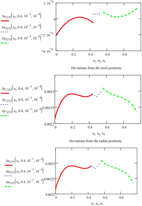
4. The quantitative influence of the wear process over the machining process
Fig. 4. Deviations from the position of the bed-slide
Based in the three cases that have been analyzed (when the bed guide only is worn, when the slide guide only is worn or both) the deviations, that characterize the accuracy loss as a result of the wear process of the friction couple elements, can be established knowing the wear size.
Thus, taking into consideration the most disadvantageous case (but the most possible one) when both the bed guide and the slide guide are worn figure 4 shows the deviation of the radius (deviations from the co-ordinate of the considered point) of axial positioning (deviations from abscises of the analyzed conditions expressed by the variation laws of the use coefficient, loading coefficient and velocity coefficient that characterize the couple wear tribologically standpoint [2].
0 0.2 0.4 0.6 0.8
4.10 6 2.10 6 0 2.10 6
Deviations from the axial positiony
∆x1231x1,0.4 10 3
−
, ,10−4
(
)
∆x2231x2,0.4 10 3
−
, ,10−4
(
)
∆x3231x3,0.4 10 3
−
, ,10−4
(
)
x1,x2,x3
0 0.2 0.4 0.6 0.8
0.0022 0.00225 0.0023
Deviations from the radial positiony ∆y1231x1,0.4 10
3
−
, ,10−4
(
)
∆y2231
(
x2,0.4,10−3,10−4)
∆y3231
(
x3,0.4,10−3,10−4)
x1,x2,x3
0 0.2 0.4 0.6 0.8
0.0022 0.00225 0.0023
Deviations from the total positiony
∆a1231
(
x1,0.4,10−3,10−4)
∆a2231
(
x2,0.4,10−3,10−4)
∆a3231
(
x3,0.4,10−3,10−4)
Fiabilitate si Durabilitate - Fiability & Durability no 2(6)/ 2010
Editura “Academica Brâncuşi” , Târgu Jiu, ISSN 1844 – 640X22
5. Conclusions
As can be noticed in figure4, the deviations of axial position (∆x) show discontinuities in the passing points from one working area to another one, function of the worn guide curve slide. This discontinuity results from the condition that the profiles of the worn mobile guide and of the fixed one are always continuously followed and they have a common contact point.
The radius deviations (∆y) are always continuous functions, so as the profiles of the machined parts in the radial direction will be “smooth” but with circular shapes of various radius.
Given the facts presented, we can conclude that by having the possibility to know the wear size beginning with the projecting status, a better choice of the material couples can be made for bed-slide, a correct evaluation of the overall dimensions of slide and of the guide can be made and an estimation closer to the ones as concerns the size of the exploitation factors (pressure, velocity, lubrication etc.).
We can’t ignore the accuracy over the machined part shape, slide that as it dread been known can be influenced in a smaller or bigger way by the shape of the bed and slide guide wear.
References
[1] Militaru, C., Fiabilitatea si precizia în tehnologia constructiilor de masini, 1987, Ed. Tehnica Bucuresti;
[2] Sandu, Gh., Moraru, V. , Minciu, C., Ghidajele masinilor unelte, 1967, Ed. Tehnica Bucuresti;
[3] Pavelescu, D., Aspecte ale modului in care este corelata evolutia procesului de frecare cu a celui de uzare. Constructia de masini 32, nr.10, 1980, p.495-499;