Universidade de Aveiro Departamento de Eletrónica,Telecomunicações e Informática
2020
Ana Patrícia
Gomes da Cruz
Aplicação de mecanismos baseados em broker para
ligação de terminais a redes móveis
Application of broker-based mechanisms for
“Ser-vos-ao dadas pistas e caminhos, contudo, o trabalho, a
perse-verança e a força de vontade, irão abrir-vos as portas dos segredos que a vossa dedicação e empenho conseguirem encontrar. Bem vindos ao vosso futuro.”
— Mário Jorge Rodrigues
Universidade de Aveiro Departamento de Eletrónica,Telecomunicações e Informática
2020
Ana Patrícia
Gomes da Cruz
Aplicação de mecanismos baseados em broker para
ligação de terminais a redes móveis
Application of broker-based mechanisms for
Universidade de Aveiro Departamento de Eletrónica,Telecomunicações e Informática
2020
Ana Patrícia
Gomes da Cruz
Aplicação de mecanismos baseados em broker para
ligação de terminais a redes móveis
Application of broker-based mechanisms for
end-node attachment in mobile networks
Dissertação apresentada à Universidade de Aveiro para cumprimento dos requisi-tos necessários à obtenção do grau de Mestre em Engenharia de Computadores e Telemática, realizada sob a orientação científica do Doutor Daniel Nunes Corujo, Professor auxiliar do Departamento de Eletrónica, Telecomunicações e Informática da Universidade de Aveiro, e do Doutor António Manuel Duarte Nogueira, Pro-fessor auxiliar do Departamento de Eletrónica, Telecomunicações e Informática da Universidade de Aveiro.
o júri / the jury
presidente / president Professor Doutor Arnaldo Silva Rodrigues de Oliveira
Professor Auxiliar do Departamento de Eletrónica, Telecomunicações e Informática da Universi-dade de Aveiro
vogais / examiners committee Doutor Sérgio Miguel Calafate de Figueiredo
Engenheiro Sénior na Altran Portugal
Professor Doutor Daniel Nunes Corujo
Professor Auxiliar do Departamento de Eletrónica, Telecomunicações e Informática da Universi-dade de Aveiro (orientador)
agradecimentos /
acknowledgements Dedico este trabalho aos meus pais, irmã, cunhado e sobrinho, a quem agradeçopelo incansável apoio, por acreditarem em mim, estarem sempre disponíveis e proporcionarem todas as condições para que este caminho fosse possível. Aproveito também para agradecer às minhas primas Mariana e Matilde, por estarem sempre comigo neste percurso.
Em segundo lugar, agradeço ao Prof. Daniel Corujo e ao Prof. António Nogueira por todo o apoio prestado ao longo da realização deste trabalho. Aproveito também para agradecer ao Instituto de Telecomunicações de Aveiro (UID/EEA/50008/2019) por fornecer todos os recursos e condições necessárias para a realização desta Dissertação.
Por último, agradeço a todos aqueles que tive oportunidade de conhecer, de convi-ver e acima de tudo por me acompanharem nesta longa caminhada; em particular, ao Marco, à Inês Moreira, ao Ricardo, ao Diogo e à Cristiana por toda a amizade, apoio e ajuda disponibilizada.
A todos Vocês, que tornaram este caminho possível, um muito obrigada!
Esta dissertação foi realizada no âmbito do projeto de investigção PTDC/EEI-TEL/30685/2017 “5G-CONTACT - 5G CONtext-Aware Communications optimi-zation” financiado pela FCT/MEC, e do projeto POCI-01-0247-FEDER-024539 “5G”, financiado pelo FEDER (através do POR LISBOA 2020 e do COMPETE 2020) e foi desenvolvida com o apoio do Instituto de Telecomunicações.
Palavras Chave 5G, 4G, EPC, 5GC, OAI, broker
Resumo Nos últimos anos, o tráfego de dados móveis tem vindo a crescer com o aumento
de equipamentos ligados à rede. Devido à demanda do utilizador, os operadores de rede necessitam de atualizar continuamente a sua rede e manter os custos baixos. Atualmente, para essa atualização, o operador precisa de adquirir novos equipamentos, tendo um investimento muito elevado. O 5G via fornecer maior escalabilidade e flexibilidade na rede. Para isso, a arquitetura do sistema 5G é construída com base numa nuvem nativa, o que significa uma arquitetura baseada em serviços na rede “core”. Este tipo de arquitetura visa fornecer conectividade independentemente da tecnologia de acesso, introduzindo maior redundância na resiliência no plano de controlo e eficiência operacional. Adicionalmente, ao invés de interfaces dedicadas entre cada par de funções de rede “core” intervenientes, as mesmas comunicam através de uma interface baseada em serviços, com vista a uma maior flexibilidade e simplicidade.
OpenAirInterface (OAI) é uma plataforma de software de código aberto que visa fornecer uma aproximação aos padrões 3GPP das redes 4G e 5G. Esta dissertação fornece um estudo do impacto de uma arquitetura baseada em serviços no plano de controlo. Para isso, utilizou-se uma arquitetura que evolui o Evolved Packet Core (EPC) para uma rede “core” próxima da 5G Core (5GC), introduzindo um broker. Um broker é integrado entre os módulos do plano de controlo, no qual estes para comunicarem entre si necessitam de realizar pedidos. A abordagem utilizada consiste na integração de um broker na plataforma OAI, avaliando o seu impacto comparando com o EPC original.
Keywords 5G, 4G, EPC, 5GC, OAI, broker
Abstract In recent years, mobile data traffic has been growing with the increase of equip-ments connected to the network. Due to user demand, network operators have to continuously upgrade their networks and keep the costs low. Nowadays, to do this upgrade, the operator needs to acquire new equipment, leading to a very high investment. 5G aims to provide more scalability and flexibility on the network. For this, the 5G system architecture is built based on a cloud-native, which means Service Based Architecture (SBA) in the core network. SBA aims to provide con-nectivity with all access technologies, introducing more redundancy in the control plane’s resiliency and operational efficiency. Additionaly, instead of using dedicated interfaces between each pair of interacting core functions, they now communicate through a Service-Based Interface (SBI), aiming for greater flexibility and simpli-city. The OpenAirInterface (OAI) is an open-source software platform that aims to provide an approximation to the 3GPP standards of the 4G and 5G networks. This thesis provides a study of the impact of the SBA in the control plane. For that, we used an architecture that evolves the Evolved Packet Core (EPC) into a core network close to 5G Core (5GC) by introducing a broker. The broker is integrated between the modules in the control plane, wherein they have to order requests to communicate with each other. The proposed architecture consists of integrating the broker on the OAI platform, evaluating it, and comparing it with the original EPC.
Contents
Contents i
List of Figures vii
List of Tables ix Glossary xi 1 Introduction 1 1.1 Motivation . . . 2 1.2 Goals . . . 2 1.3 Document structure . . . 3
2 State of the Art 5 2.1 Evolved Packet System (EPS) . . . 5
2.1.1 User Equipment . . . 7
2.1.2 Access Network . . . 8
2.1.3 Core Network . . . 9
2.1.3.1 Mobility Management Entity (MME) . . . 9
2.1.3.2 Home Subscriber Server (HSS) . . . 10
2.1.3.3 Serving Gateway (S-GW) . . . 10
2.1.3.4 Packet Data Network Gateway (P-GW) . . . 10
2.1.3.5 Policy and Charging Rules Function (PCRF) . . . 11
2.1.4 Communication Protocols . . . 12
2.1.4.1 Radio Resource Control Protocol (RRC) . . . 12
2.1.4.2 Packet Data Convergence Protocol (PDCP) . . . 13
2.1.4.4 Medium Access Control Protocol (MAC) . . . 13
2.1.4.5 Physical Layer . . . 13
2.1.4.6 S1 Application Protocol (S1AP)/Non-Access Stratum (NAS) 13 2.1.4.7 Diameter . . . 14
2.1.4.8 GPRS Tunneling Protocol (GTP) . . . 14
2.1.5 Connection Procedures . . . 14
2.1.5.1 The EPS Bearer . . . 15
2.1.5.2 LTE authentication . . . 15
2.1.5.3 Attach Procedure . . . 16
2.1.6 LTE implementation platforms . . . 18
2.1.6.1 OpenLTE . . . 18
2.1.6.2 srsLTE, srsUE, srsENB . . . 18
2.1.6.3 OpenEPC . . . 18
2.1.6.4 NextEPC . . . 19
2.1.6.5 GR-LTE . . . 19
2.1.6.6 Open-Source LTE Deployment (OSLD) . . . 19
2.1.6.7 AMARISOFT LTE . . . 19
2.1.6.8 OpenAirInterface (OAI) . . . 19
2.2 5G network . . . 23
2.2.1 Core netwok . . . 24
2.2.1.1 Access and Mobility Management Function (AMF) . . . . 24
2.2.1.2 Session Management Function (SMF) . . . 24
2.2.1.3 User Plane Functions (UPF) . . . 25
2.2.1.4 Policy Control Function (PCR) . . . 25
2.2.1.5 Network Exposure Function (NEF) . . . 25
2.2.1.6 Network Repository Function (NRF) . . . 25
2.2.1.7 Unified Data Management (UDM) . . . 25
2.2.1.8 Authentication Server Function (AUSF) . . . 25
2.2.1.9 Application Function (AF) . . . 25
2.2.1.10 Unified Data Repository (UDR) . . . 25
2.2.1.11 Network Slice Selection Function (NSSF) . . . 26
2.3 Brokers . . . 26
2.3.1 Software Solutions . . . 26 ii
2.3.1.1 RabbitMQ . . . 26
2.3.1.2 Eclipse Mosquitto . . . 28
2.3.1.3 Kafka . . . 29
2.4 Summary . . . 30
3 Architecture and Specifications 31 3.1 Problem statement . . . 31
3.2 Requirements and Specifications . . . 32
3.2.1 Selection of LTE implementation . . . 32
3.2.2 OAI . . . 33 3.2.3 Brokers . . . 34 3.3 Proposed solution . . . 35 3.3.1 Architecture . . . 35 3.4 Introducing brokers . . . 36 3.4.1 Attachment Procedure . . . 37 3.5 Execution Procedure . . . 38
3.5.1 Execution procedure for LTE . . . 38
3.5.2 Execution procedure for message brokers . . . 39
3.6 Summary . . . 40
4 Implementation 41 4.1 Overview . . . 41
4.1.1 Virtual Machine Specifications . . . 42
4.2 Radio Access Network (RAN) . . . 42
4.2.1 Evolved NodeB (eNB) . . . 42
4.2.1.1 Hardware Setup . . . 42
4.2.1.2 Software Setup . . . 42
4.2.2 UE Setup . . . 43
4.2.3 Run eNB and UE . . . 43
4.3 Core Network . . . 44
4.3.1 HSS + MME . . . 44
4.3.1.1 Configuring and building HSS . . . 44
4.3.1.2 Configuring and building MME . . . 45
4.4 Adaptations to HSS+MME and S/P-GW . . . 45 4.4.1 RabbitMQ . . . 47 4.4.1.1 Publisher/Subscriber . . . 47 4.4.2 Mosquito MQTT . . . 48 4.4.2.1 Publisher . . . 50 4.4.2.2 Subscriber . . . 50 4.4.3 Kafka . . . 51 4.4.3.1 Publisher . . . 51 4.4.3.2 Subscriber . . . 51 4.4.4 Message broker VM . . . 52
4.5 Extraction data from captures . . . 52
4.6 Summary . . . 54 5 Results 55 5.1 Scenario . . . 55 5.2 Data Gathering . . . 56 5.3 Signaling Impact . . . 56 5.3.1 Messages defined by 3GPP . . . 56
5.3.2 Size of messages using brokers . . . 57
5.3.3 Throughput . . . 58
5.4 Delay on the control plane . . . 59
5.4.1 Delay between UE+eNB and MME entities . . . 59
5.4.2 Delay between MME and HSS entities . . . 61
5.4.3 Delay between MME and S/P-GW entities . . . 62
5.4.4 Delay in broker entity . . . 65
5.5 Attachment Time . . . 65
5.5.1 Original EPC . . . 65
5.5.2 Message Brokers . . . 66
5.5.3 Comparison between original EPC and message brokers . . . 67
5.6 Total Time . . . 68
5.6.1 Original EPC . . . 69
5.6.2 Message Brokers . . . 70
5.6.3 Comparison total time between original EPC and message brokers . 70 5.7 Latency . . . 71
5.8 Summary . . . 72
6 Conclusions 75 6.1 Future work . . . 76
References 77 Appendix-A: oai-mme/oai-spgw source code modifications 81 A.1 Broker init connection configurations . . . 81
A.2 Broker information structure . . . 81
A.3 Changes on nwGtpv2cCreateAndSendMsg function . . . 81
A.4 Init broker connection in s11_mme_task.c . . . 82
A.5 Init publisher . . . 82
Appendix-B: RabbitMQ implementation 85 B.1 publisher and subscriber methods . . . 85
B.1.1 Establishment the connection . . . 85
B.1.2 Private reply queue . . . 85
B.1.3 Publish the message . . . 85
B.1.4 Subscriber method . . . 86
Appendix-C: Mosquitto implementation 87 C.1 Similar methods for publisher and subscriber . . . 87
C.1.1 Create the client . . . 87
C.1.2 Establishment the connection . . . 87
C.2 Publish the message . . . 87
C.3 Subscribe the message . . . 88
Appendix-D: Kafka implementation 89 D.1 Create the client . . . 89
D.2 Publish the message . . . 89
D.3 Subscribe the message . . . 89
Appendix-E: Extraction data from captures 91 E.1 Extraction S1AP captures . . . 91
E.3 Extraction Diamater captures . . . 93
List of Figures
2.1 The Evolved Packet System network elements. . . 6
2.2 Functional split between E-UTRAN and EPC (adapted from [11]). . . 7
2.3 Internal architecture of the UE (adapted from [14]). . . 8
2.4 Architecture of E-UTRAN (adapted from [11]). . . 9
2.5 User plane protocol stack[15]. . . 12
2.6 Control plane protocol stack[15]. . . 12
2.7 EPS Bearer Architecture [11] . . . 15
2.8 EPS attach procedure . . . 16
2.9 OpenAirInterface protocol stack (source [36]). . . 20
2.10 Brief representation of the modules implemented by OpenAirInterface . . . 21
2.11 Main architecture options proposed by 3GPP for 5G evolution. . . 23
2.12 5G Architecture [38] . . . 24
2.13 Simplified RabbitMQ architecture. . . 27
2.14 RabbitMQ RPC system. . . 28
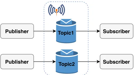
2.15 Simplified MQTT architecture using Mosquitto broker. . . 29
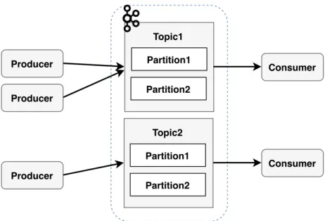
2.16 Simplified Kafka architecture. . . 30
3.1 LTE network elements implemented by OpenAirInterface [53]. . . 33
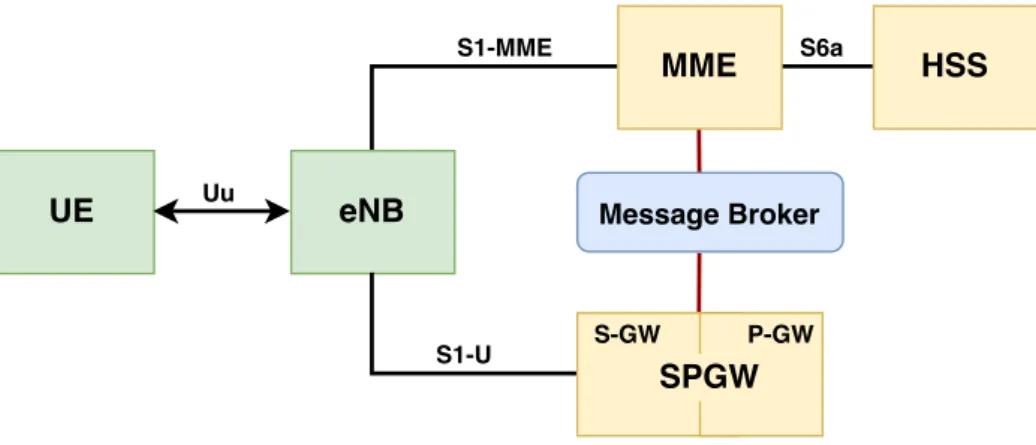
3.2 Illustration of the integration of the broker between the core elements and eNB. 35 3.3 Proposed solution architecture. . . 36
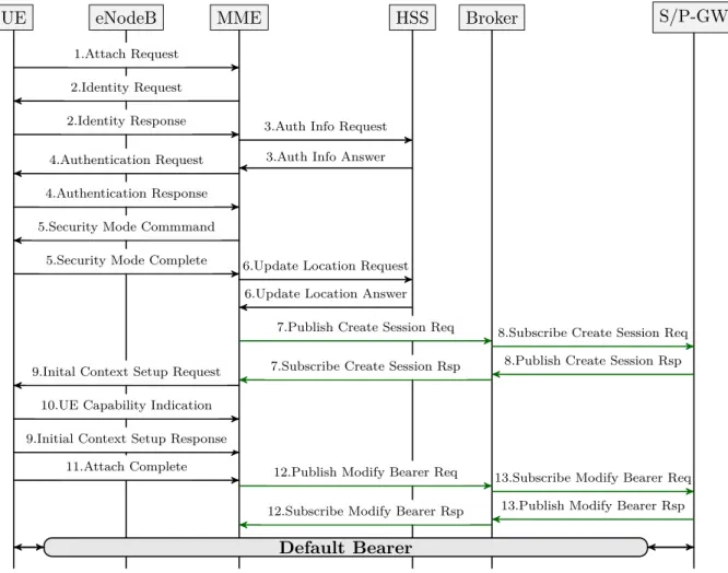
3.4 Attachment procedure using a broker. . . 37
3.5 EPS execution procedure . . . 38
3.6 Execution procedure using a broker. . . 39
4.1 Architecture implementation in Openstack cloud environment. . . 41
4.3 RabbitMQ flow using RPC method. . . 49 4.4 Mosquitto MQTT flow. . . 50 4.5 Kafka flow. . . 52 4.6 Implementation of the Flask server. . . 53 5.1 OAI with and without message broker scenario. . . 56 5.2 Delay time for messages exchanged with UE+eNB and MME for original EPC. . 60 5.3 Delay time for each pair of messages exchanged between HSS and MME entities. 62 5.4 Delay time comparison for the message pair msg6 for different implementations. 62 5.5 Delay time comparison for the message pair msg10 for different implementations. 63 5.6 Delay time comparison for the message pair msg11 for different implementations. 64 5.7 Delay time for each request and response messages in broker entity. . . 65 5.8 Attachment time for original EPC . . . 66 5.9 Attachment time comparison between message brokers. . . 67 5.10 Attachment time comparison between original EPC and message brokers. . . 68 5.11 Total time for original EPC. . . 69 5.12 Total time using message brokers. . . 70 5.13 Total time comparison between original EPC and message brokers. . . 71 5.14 Comparison between original EPC and different brokers in terms of latency. . . . 72
List of Tables
2.1 Comparison of the network elements between 4G and 5G system. . . 26 3.1 Comparison between LTE implementations platforms. . . 33 4.1 Resources used by each VM. . . 42 4.2 OAISIM file configuration. . . 43 4.3 Main configuration of the HSS files. . . 44 4.4 Example of user subscribers. . . 44 4.5 MME file configuration. . . 45 4.6 Version of server brokers. . . 52 5.1 Size of messages defined by 3GPP. . . 57 5.2 Size of messages sent through the different brokers. . . 57 5.3 Mean throughput per interface for different implementation. . . 58 5.4 Assign a delta message to the different pairs of messages. . . 59
Glossary
3G Third Generation
3GPP Third Generation Partnership
Project
4G Fourth Generation 5G Fifth Generation 5GC Fifth Generation Core
AAA Authentication, Authorization and
Accounting
AES Advanced Encryption Standard AF Application Function
AKA Authentication and Key Agreement ALOE Abstraction Layer and Open
Operating Environment
AMF Access and Mobility Management
Function
AMQP Advanced Message Queuing
Protocol
AN Acces Network
APN Access Point Name AS Access Stratum AuC Authentication Center
AUSF Authentication Server Function AUTN Authentication Token
AV Authentication Vector AVP Attribute Value Pair BIOS Basic Input/Output System CAPEX Capital Expenditure
CK Cipher Key
CN Core Network
CPU Central Processing Unit
DHCP Dynamic Host Configuration
Protocol
DL Downlink
DNS Domain Name System eMBB Enhanced Mobile Broadband EMM EPS Mobility Management eNB Evolved NodeB
EPC Evolved Packet Core EPS Evolved Packet System
E-RAB E-UTRAN Radio Access Bearer ESM EPS Session Management
E-UTRA Evolved Universal Terrestrial Radio
Access
E-UTRAN Evolved Universal Terrestrial Radio
Access Network
GBR Guaranted Bit Rate
GR GNU Radio
GSM Global System for Mobile
Communications
GTP GPRS Tunnelling Protocol GUMMEI Globally Unique MME Identifier GUTI Globally Unique Temporary Identity HARQ Hybrid Automatic Repeat Request HLR Home Location Register
HPLMN Home Public Land Mobile Netwok HSS Home Subscriber Server
ICMP Internet Control Message Protocol ICT Information and Communication
Technologies
IK Integrity Key
IMEI International Mobile Equipment
Identity
IMSI International Mobile Subscriber
Identity
IoT Internet of Things IP Internet Protocol ITTI Inter-task Interface LTE Long Term Evolution MAC Medium Access Control
MBMS Multimedia Broadcast Multicast
Services
MBR Maximum Bit Rate MCC Mobile Country Code ME Mobile Equipment
MME Mobility Management Entity mMTC Massive Machine Type
Communication
MNC Mobile Netwok Code
MQTT Message Queue Telemetry Transport MSIN Mobile Subscription Identification
Number
MSISDN Mobile Station International
Subscriber Directory Number
MT Mobile Termination
N3IWF Non-3GPP InterWorking Function NAS Non-Access Stratum
NEF Network Exposure Function NF Network Function
NR New Radio
NRF Network Repository Function NSA Non Standalone
NSSAI Network Slice Selection Assistance
Information
NSSF Network Slice Selection Function OAI OpenAirInterface
OAISIM OpenAirInterface System Emulation OPEX Operational Expenditure
OS Operating System
OSA OpenAirInterface Software Alliance OSLD Open-Source LTE Deployment PCEF Policy and Charging Enforcement
Function
PCR Policy Control Function
PCRF Policy and Charging Rules Function PDCP Packet Data Convergence Protocol PDN Packet Data Network
PDU Packet Data Unit
P-GW Packet Data Network Gateway PHY Physical Layer
PLMN Public Land Mobile Netwok PS Packet Switched
QCI Quality of Service Class Identifier QoS Quality of Service
RAM Random Access Memory RAN Radio Access Network RAND Random Number
RAT Radio Access Technology RLC Radio Link Control RPC Remote Procedure Call RRC Radio Resource Control S/P-GW Serving/PDN Gateway S1AP S1 Application Protocol
SA Standalone
SAE System Architecture Evolution SBA Service Based Architecture SBI Service Based Interface SCM Security Context Management SCTP Stream Control Transmission
Protocol
SDF Service Data Flow SDR Software Defined Radio SEAF Security Anchor Function S-GW Serving Gateway
SIM Subscriber Identity Module SM Session Management
SMF Session Management Function SPR Subscription Profile Repository SRB Special Radio Bearer
TAC Tracking Area Code TAI Tracking Area Identity TCP Transmission Control Protocol TE Terminal Equipment
TEID Tunnel Endpoint Identifier xii
TFT Traffic Flow Template UDM Unified Data Management UDP User Datagram Protocol UDR Unified Data Repository UE User Equipment
UICC Universal Integrated Circuit Card
UL Uplink
UMTS Universal Mobile
Telecommunications System
UPF User Plane Functions
UPF User Plane Functions
URLLC Ultra-Reliable and Low Latency
Comumunications
USIM Universal Subscriber Identity
Module
USRP Universal Radio Peripheral VM Virtual Machine
VoIP Voice over Internet Protocol X2AP X2 Application Protocol XRES Expected Response
CHAPTER
1
Introduction
Over the years, mobile telecommunications and the number of equipments needing a connection to the network have been growing. The Fourth Generation (4G) network provides high data rates and low complexity when compared with the previous generation networks.
In 2017, mobile data traffic increased by 71 percent. It is predictable that, by 2022, mobile data traffic keeps growing, reaching 77 exabytes per month. That points to approximately one zettabyte per year. Besides the expectations about the increasing mobile traffic of 4G, it is expected that Fifth Generation (5G) will reach 12 percent by 2022. Furthermore, until 2022, global mobile traffic is expected to rise seven-fold [1]. With the 4G evolution, new services appeared, and not only human customers take advantage of using it but also Internet of Things(IoT) services, such as cars, sensors, among others. The network operators are continuously upgrading and extending their network infrastructure to attend the user demand of data and services, increasing not only in Capital Expenditure (CAPEX) but also in Operational Expenditure (OPEX). On the other hand, the revenue per user is not enough to cover the investment, resulting in losses. To reduce costs and increase revenue, network operators need to progress their mobile networks to 5G [2].
5G network is being developed due to the rise of data traffic and demand for a high data rate as well as to reduce the costs. 5G considers three main scenarios: enhanced mobile broadband (eMBB), massive machine type communication (mMTC), and ultra-reliable low latency communications (URLLC). The 5G Core Network (5GC) architecture is built upon in Service Based Architecture (SBA), which takes advantage of the service concept, i.e., multiple services are provided by Network Functions (NF) and services communicate with each other through general interfaces [3]. Considering the HTTP-based (e.g., REST) nature of such interactions, this approach to web-based
technologies allows new ideas to be pursued in the domain of cloud-native mobile networks, such as the exploration of broker-based interactions between the elements of the mobile core network. Furthermore, 5GC provides architectural agility enabling 1:N redundancy for control plane resiliency, processing efficiency, and operational efficiency (CAPEX and OPEX)[4].
Third Generation Partnership Project (3GPP)1 is an organization that develops telecommunications standards. This community works on cellular telecommunications technlogies, such as radio access, core network and service capabilities, providing a complete system for mobile telecommunication [5]. Projects like OpenAirInterface(OAI)2 are developed to emulate and simulate the 4G/5G networks following 3GPP standards.
1.1 Motivation
The future network of 5G mobile telecommunications will depend on a reformulation of the architecture of its core, standardized by 3GPP in standard TS 23.501.
This new architecture is different from the previous ones by including mechanisms that allow the network to increase the capacity to integrate different types of usage scenarios, evidenced by the increasing integration of Information and Communication Technologies (ICT) in various sectors of our society.
The new architecture also shows an evolution of mobile network core architecture closer to cloud-native systems and technologies, allowing operators to benefit from added flexibility and cost savings. As a result, this opens up the way for further research concerning the impact of the adoption of other computer system-related mechanisms, such as the utilization of message brokers for control signaling routing.
Although there are some open-source software platform that implement the core network of the operator, like OAI, they are still associated with the 4G standard and there are no implementations with 5G.
1.2 Goals
The focus of this thesis is to evolve the 4G network by introducing message brokers between core entities. That means we will use message brokers to make the signaling routing between the core entities, removing the dedicated interfaces of 4G. For that, we will use a software platform, OAI, developed with the 4G standard.
The OAI platform will be analyzed in terms of code structure, functionality, and what type of emulation it is possible to achieve. The message brokers will be integrated into the proper modules of the platform. Subsequently, the traffic will be analyzed for
13GPP: https://www.3gpp.org/
2OpenAirInterface: https://www.openairinterface.org/
both implementations with and without a broker. Furthermore, their impact will be evaluated with multiple users in the network.
1.3 Document structure
The remainder of this document is organized in the following way. Chapter 2 describes the relevant 3GPP standards of the 4G network as well as the different open-source 4G software platforms, the 5G network standards, and the brokers used for the imple-mentation. Chapter 3 provides the requirements needed to build the solution and a detailed description of the proposed architecture. Chapter 4 presents the architecture’s implementation details such as hardware and software that were used and all the configurations needed. Chapter 5 presents the analysis of the results gathered. Finally, chapter 6 presents the work conclusion and future work.
CHAPTER
2
State of the Art
This chapter gives an overview of all the concepts that are necessary to understand this document. The goal of this thesis is to evolve the EPC into a core network close to 5GC, while integrating a broker. For that, it is first necessary to understand the scope of the 4G and 5G networks.
The first section of this chapter addresses the EPS by describing its architecture and exposing some LTE software platforms. The second section presents an overview of the 5G network. The last section describes different brokers.
2.1 Evolved Packet System (EPS)
In 2004, the 3GPP started to study the evolution of the 3G Universal Mobile Telecom-munications System (UMTS) system. The reasons were to keep 3G system competitive. The first release documented of EPS specifications was Release 8, completed in 2008. The main motivations behind this were an optimized Packet Switched (PS) system, which answers the user’s demand for Quality of Service (QoS) and high data rates, low complexity, and to keep the need for cost reduction, such as CAPEX and OPEX [6].
Simultaneously, the 3GPP community worked on the evolution of the core network called System Architecture Evolution (SAE), wherein it defines an all-Internet Protocol (IP) network architecture. There were two main reasons to design this new architecture.
The first one was to have a “flat architecture” which means fewer network nodes were implicated in the user’s data traffic, allowing performance and cost-efficiency. The second reason was to separate the signaling (known as control plane) from the user’s data (known as user plane) to allow them to scale independently [7].
3GPP communications have continued to increase data rates, increasing the num-ber of active subscrinum-bers at the same time, and improving performance, which was
documented on release 10, completed in 2011. Release 10, known as LTE-Advanced, corresponds to the 4G of the mobile telecommunications network [8].
There are three main components that integrate the EPS, namely the user equipment (UE), the access network (Long Term Evolution (LTE) or Evolved Universal Terrestrial Radio Access Network (E-UTRAN)), and the core network, the Evolved Packet Core (EPC). Figure 2.1 shows the functional components and the standardized interfaces of
EPS. S-GW P-GW PCRF HSS External networks/ Operator services (IMS) EPC S1-U S11 S5/S8 S6a Rx Gx SGi Control Plane User Plane UE E-UTRAN LTE-Uu eNB eNB eNB X2 X2 X2 S1-MME MME S10
Figure 2.1: The Evolved Packet System network elements.
EPS provides to the user an IP address to a Packet Data Network (PDN) for accessing some services such as Voice over Internet Protocol (VoIP) and Internet. All data traffic is transported using bearers (section 2.1.5) through QoS policies from the gateway in PDN to the UE. Multiple bearers may be associated to each user to provide them with different QoS streams or to associate them to different PDNs. The E-UTRAN deals with tasks associated with radio functionality of the EPS like encryption and scheduling. The EPC deals with non-radio tasks [9].
As represented in figure 2.1, the core network has many logic nodes, whereas the access network only has one, the Evolved NodeB (eNB). Each one of these elements interconnects through standardized interfaces. It allows operators to choose their networks by splitting or merging these network elements [10]. Figure 2.2 depicts the principal functions between the E-UTRAN and EPC. The following subsections describe the network elements in more detail.
Inter Cell RRM
Radio bearer control
Dynamic resource allocation (scheduling)
Radio admission control
Measurement reporting configuration for mobility
E-UTRAN RRC PDCP MAC RLC PHY Protocol Stack Internet Mobility anchoring S-GW
NAS Security Roaming
Bearer management Idle state mobilityhandling MME UE IP address allocation Packet filtering P-GW EPC S1
Figure 2.2: Functional split between E-UTRAN and EPC (adapted from [11]).
2.1.1 User Equipment
The architecture of the UE is the same as previous generations UMTS and Global System for Mobile Communications (GSM), shown in figure 2.3.
The mobile equipment (ME) is known as the present communication device. The ME is split into two components, the mobile termination (MT), which deals with all the communication functions, and the terminal equipment (TE), which terminates the data streams.
The universal integrated circuit card (UICC) is a smart card, known as the subscriber identity module (SIM) card. When the UICC is activated, the ME selects a universal subscriber identity module (USIM) application. After a successful USIM application selection, the USIM selected is stored on the UICC, which saves specific user data like the user’s phone number and home network identity. The USIM executes different security-related calculations, having the secure keys stored in the smart card. The LTE network supports mobile devices that are using a USIM from Release 99 or later. However, it does not support the SIM used by previous releases of GSM [12], [13].
TE MT UICC R Cu ME UE
Figure 2.3: Internal architecture of the UE (adapted from [14]).
2.1.2 Access Network
Figure 2.4 represents the E-UTRAN architecture. The access network, E-UTRAN, deals with the radio communications between the mobile and the EPC and it is only composed by one component, the eNB. The E-UTRAN consists of a network of eNBs, providing the Evolved Universal Terrestrial Radio Access (E-UTRA) user plane and control plane terminations towards the UE (more information concerning protocols on section 2.1.4).
Each eNB may be connected to each other through the X2 interface. It also connects to EPC using the S1 interface that subdivides into S1-MME, connected to Mobility Management Entity (MME), and S1-U, connected to Serving Gateway (S-GW). The S1 interface has the functionality to support multiple connections between MME/S-GW. The eNB is responsible for all radio related roles like functions for radio resource management. It covers features associated with the radio bearers like radio bearer control, radio admission control, connection mobility control, scheduling, and dynamic allocation of resources to UEs in both uplink and downlink. Furthermore, it determines which of the MMEs would receive the signaling sent from UE. This MME will serve the UE while it is in the radio coverage of the pool area wherein the MME is associated. However, when the UE moves to a new pool area and into a new pool area, the new MME will send the Identification Request or the Context Request messages to the old MME using Globally Unique Temporary Identity GUTI [11], [15].
UE S-GW MME E-UTRAN LTE-Uu eNB eNB eNB X2 X2 X2 Control Plane User Plane S1-MME S1-MME S1-U S1-U
Figure 2.4: Architecture of E-UTRAN (adapted from [11]).
2.1.3 Core Network
The core network, known as EPC, is the cornerstone of the EPS. It is responsible for the overall control of the UE and the establishment of bearers. The EPS provides the bearer path with some QoS policies. However, the control of multimedia applications (VoIP) is supplied by the IP Multimedia Subsystem (IMS), which is designed to be
outside the EPS.
The elements that compose the core network displayed in figure 2.1 are discussed below in more detail.
2.1.3.1 Mobility Management Entity (MME)
The MME is the main control plane element of the LTE network. The MME processes Non-Access Stratum (NAS) signaling between the EPC and the UE, which is responsible for idle mode UE tracking and paging procedures. The main functions supported by the MME are classified as:
• bearer related functions which include the establishment, maintenance and release of the bearers, and is handled by the session management layer in the NAS protocol;
• connection management functions which include the establishment of the con-nection and security between the network and the UE, and is handled by the mobility management layer in the NAS protocol.
A typical network may include multiple MMEs. Each of them are selected for operations based on the geographical location or distances from the UE. After being selected, the MME selects other network elements required for the service, such as S-GW and P-GW. The MME gets and stores the location reports, sent by the UEs. When the UE needs to be paged, it uses this data to do so. The MME also presents a significant role in the authentication process in interfaces with HSS for getting and
providing subscribers data. When there are multiple MME in the LTE network, the S10 interface is used to connect them. When a new MME is selected to serve a specific UE, the new MME can contact the old MME through S10 to retrieve data about the identity(MME), security information, and information related to active bearers (PDN gateways to communicate, QoS) [15].
2.1.3.2 Home Subscriber Server (HSS)
The HSS is the central subscriber database of the LTE networks. It is a combination of the Home Location Register (HLR) and Authentication Center (AuC) from previous 3GPP versions. The HSS stores permanent subscription details for its subscriber in the network, including the authentication key. It also saves the temporary mobility and service data for every subscriber. During a user’s authentication, the HSS provides the MME with an authentication vector based on the authentication key, that can verify if a specific user can be allowed to connect to PDN. However, the authentication key itself never leaves the HSS [16].
2.1.3.3 Serving Gateway (S-GW)
The S-GW terminates the user plane towards E-UTRAN. For each UE associated with the EPS, there is a single S-GW, at a given time. One S-GW could connect to multiple eNBs, and one eNB could connect to various S-GWs.
Moreover, this entity works as a mobility anchor point for inter-eNodeB and intra-3GPP handover without changes in the S-GW. Concerning inter-eNodeB handovers, the S-GW is responsible for notifying the source eNB after switching the path and not receiving traffic for handed over UE. When the UE is in idle mode, the S-GW buffers the downlink packets to this user and initiates a network triggered service request procedure by the MME. When the UE moves, the S-GW might change, which is selected by the related MME.
Other roles include [15]: • lawful interception
• packet routing and forwarding;
• transport level packet marking in the Uplink(UL) and Downlink(DL) (based on the metrics of the associated EPS bearer) .
2.1.3.4 Packet Data Network Gateway (P-GW)
The P-GW is the entity that communicates the data plane traffic to and from external PDNs through the SGi interface. The network usually includes one or more P-GWs for each type of external PDN connection, such as the Internet, the network operator’s servers, or the IMS. Each PDN is identified by an access point name (APN). Also, the P-GW can provide connectivity to UEs using non-3GPP access networks. The P-GW
is also responsible for allocating the IP addresses to the UEs. Each mobile device is assigned to a default P-GW [13].
The main functions include [16]:
• per-user based packet filtering (by e.g., deep packet inspection); • lawful interception;
• the transport level packet marking in the UL and DL is based on the quality of service class identifier (QCI) of the associated EPS bearer;
• UL and DL service level charging, rate enforcement and gating control;
• DL rate enforcement based on the accumulated maximum bit rates (MBRs) of the aggregated of service data flows (SDFs) with the same guaranted bit rate (GBR) QCI;
• DHCP (server and client) functions.
Furthermore, this entity includes functions UL and DL bearer binding, i.e., represents an association between an SDF and a bearer in the access network to transport that SDF. Some functionalities, like SDF detection, policy enforcement, and flow-based charging, are supported by the entity, namely Policy and Charging Enforcement Function (PCEF), which is located at the gateway [17]. The S-GW and P-GW entities, according to 3GPP standards, could be implemented as separated entities or as a single entity, removing the S5/S8 interface [15].
2.1.3.5 Policy and Charging Rules Function (PCRF)
PCRF is the entity responsible for policy control decision concerning SDF detection, gating, QoS policies and flow based charging towards the PCEF, which resides in the P-GW. All the security procedures required by the operator are applied before this entity accepts service information from the application function (AF). This entity, also, has to decide how a specific subscription profile repository (SPR) shall be treated in the PCEF, and ensure that the PCEF user plane traffic mapping and treatment is by the user’s subscription profile. So, its inputs are the SPR, the AF, and the predefined rules. The SPR is a logical entity containing all subscription-related information needed for subscription-based policies, for example, the subscriber’s allowed services, and the information on the subscriber’s allowed QoS. The AF is an element that extracts session information from the server application and provides it to the PCRF. The PCRF authorizes QoS resources. It uses the service information received from the AF and the subscription information received from the SPR to calculate the proper QoS authorization. Also, it may take into account the request QoS received from the PCEF through Gx interface [10], [17].
2.1.4 Communication Protocols
All interfaces mentioned previously are associated with a protocol stack, which the network elements use for data and signaling messages. The protocol stack consists of two planes: the user plane, which handles the user data traffic, and the control plane, which handle signaling messages that are just for control between the network elements. Figure 2.5 and figure 2.6 present the protocols associated to user plane and control plane, respectively, and each of their interfaces. The main functions of the different protocols are described below [11], [13], [18].
Application IP PDCP RLC MAC L1 PDCP RLC MAC L1 GTP-U UDP/IP L2 L1 GTP-U UDP/IP L2 L1 GTP-U UDP/IP L2 L1 GTP-U UDP/IP L2 L1 UE eNodeB S-GW P-GW IP LTE-Uu X2 S5/S8 SGi Application IP L1 L2 PDN GTP-U UDP/IP L2 L1 S1-U eNodeB
Figure 2.5: User plane protocol stack[15].
GTP-C UDP L2 L1 IP GTP-C UDP L2 L1 IP MME S10 MME Diameter SCTP L2 L1 IP HSS GTP-C UDP L2 L1 IP MME S6a NAS RRC PDCP RLC MAC L1 PDCP RLC MAC L1 S1-AP IP L2 L1
UE LTE-Uu eNodeB S1-MME
RRC SCTP S1-AP IP L2 L1 SCTP NAS GTP-C UDP L2 L1 IP MME GTP-C UDP L2 L1 IP S-GW GTP-C UDP L2 L1 IP P-GW S5/S8 GTP-C UDP L2 L1 IP S11
Figure 2.6: Control plane protocol stack[15].
2.1.4.1 Radio Resource Control Protocol (RRC)
The radio resource control (RRC) sublayer is responsible for handling the access network-related procedures, including the broadcast of system information that the device needs
to communicate with a cell (non-access stratum (NAS) and access stratum (AS)). Also, it is responsible for the transmission of paging messages from the MME to the device to notify about new connection requests, configure radio bearers, and mobility functions such as handover, and UE cell (re)selection.
2.1.4.2 Packet Data Convergence Protocol (PDCP)
The packet data convergence (PDCP) sublayer manages RRC messages in the control plane and IP packets in the user plane. Regarding the user plane, it performs header compression and decompression, ciphering and deciphering, and retransmission during handover. For the control plane it involves ciphering and integrity protection.
2.1.4.3 Radio Link Control Protocol (RLC)
The radio link control (RLC sublayer is responsible for concatenation, segmentation of IP packets, and tracks packets that were sent or received. It has three modes of transmission: Transparent Mode (TM), Unacknowledged Mode (UM), and Acknowledged Mode (AM).
2.1.4.4 Medium Access Control Protocol (MAC)
The medium access control (MAC) sublayer handles the mapping between logical and transport channels. It also handles uplink and downlink scheduling, multiplexing/de-multiplexing of logical channels, and error correction through hybrid automatic repeat request (HARQ). The MAC supplies services to the RLC in the form of logical channels.
2.1.4.5 Physical Layer
The physical layer (PHY) provides services to the MAC sublayer by using transport channels. Besides, it handles coding/decoding, modulation/demodulation, among others.
2.1.4.6 S1 Application Protocol (S1AP)/Non-Access Stratum (NAS)
The MME controls the eNB into its pool area through the S1AP. The main functions related to the S1AP are E-RAB management functions (setting up, modifying and releasing E-UTRAN Radio Access Bearers (E-RAB) that are triggered by the MME), initial context transfer function, mobility functions, UE capability Info Indication function, paging, NAS signaling transport function between the UE and MME, and location reporting which allows MME to know UE’s current location [19]. S1AP utilizes Stream Control Transmission Protocol (SCTP).
The NAS protocol establishes a logical connection between the UE and the MME. The eNB transmits the NAS messages between LTE-Uu and S1-MME interfaces. The main functions are:
• the support of session management procedures to establish and maintain IP connectivity between the UE and a P-GW.
The NAS procedures are grouped into two categories: EPS mobility management (EMM), which is related with mobility over E-UTRAN access, authentication and security, and EPS session management (ESM), which offers support to the establishment and handling of user data [20].
2.1.4.7 Diameter
The diameter protocol aims to provide authentication, authorization, and accounting (AAA) for applications such as network access or IP mobility and runs over Transmission Control Protocol (TCP) or SCTP. It gives the ability to exchange messages and delivery Attribute Value Pairs (AVPs), capabilities negotiation, error notification, and extensibility, which provide the addiction of new applications, commands, and AVPs. All delivered data is in the form of AVPs. The use of the AVPs by this protocol is to provide [21]:
• user authentication information, which enables the Diameter server to authenticate the user;
• service specific authorization information, between clients and servers, to allow whether a user’s access request should be granted;
The S6a interface is responsible for enabling the transfer of subscriber related data between the HSS and MME, which is defined in [22].
2.1.4.8 GPRS Tunneling Protocol (GTP)
The GTP is a tunneling protocol with a version for control plane (gtpv2) and a version for user plane (gtpv1). Both versions run over the User Datagram Protocol (UDP). To separate traffic into different communications flows GTP tunnels are used. A GTP tunnel in each node is identified with a Tunnel Endpoint Identifier (TEID), an IP address and a UDP port number. All data traffic is transported by using bearers based on GTP, and there is at least one tunnel for each UE attached. Between the S-GW and the P-GW, the interface could be called S5 or S8, according to the scenario. If it is a roaming scenario, the interface is called S5. Otherwise, if it is a non-roaming scenario, the interface is called S8, where typically the S-GW is in the visited network, and the P-GW is in the home network.
2.1.5 Connection Procedures
The following sub-sections describe the user connections procedures such as the au-thentication and attachment and the way that the user can request a service to the network.
2.1.5.1 The EPS Bearer
The EPS bearer is a tunnel responsible for transporting all data traffic between the UE and the P-GW, with a specific QoS. An EPS bearer consists of one or more service data flows such as streaming video application, and each service data flow comprises one or more packet flows like video streaming. All the packets that flow into a specific EPS bearer has the same QoS.
Whenever a mobile connects to a PDN, a default EPS bearer is created and remains established until the EPS session is finished. At the same time, the mobile receives an IP address to communicate with that network. The default bearer has a default QCI and a maximum bit rate. After the establishment of the default bearer, if an application or service needs particular QoS policies, a dedicated bearer is created. The dedicated bearer offers better QoS than the default bearer and can have a GBR.
Each EPS bearer is associated with a traffic flow template (TFT) that consists of a set of packet filters, and that filtering could be a port number or IP address.
The EPS bearer covers three different interfaces, so it cannot be implemented directly. The solution for this problem is broken down in three lower-level bearers, namely the radio bearer, the S1 bearer, and the S5/S8 bearer. Each of these has specific QoS policies. The radio bearer is implemented with a proper configuration of the LTE-Uu interface protocols, while the S1 and S5/S8 bearer are implemented using GTP tunneling. The E-RAB is a combination of the radio bearer and S1 bearer, which are illustrated in the figure 2.7 [13], [15].
PDN EPS Bearer E-RAB Radio Bearer S5/S8 Bearer S1 Bearer UE eNB S-GW P-GW S5/S8 Bearer LTE-Uu S1 S5/S8
PDN Connection (EPS Session) UE IP address
SGi
Figure 2.7: EPS Bearer Architecture [11]
2.1.5.2 LTE authentication
The authentication consists of the process to verify if a user is an authorized subscriber to the network that he is trying to access. The EPS Authentication and Key Agreement (AKA) corresponds to the mutual authentication and key agreement procedure used
After an attach request received from the UE, the MME knows the identity of the user through its IMSI, and it requests an authentication vector (AV) from the HSS. The HSS generates AVs, which are composed by the next keys:
• Integrity Key (IK) • Cipher Key (CK)
• Random Number (RAND) • Expected Response (XRES) • Authentication Token (AUTN)
After receiving the AV, the MME sends the RAND and AUTN to the UE. Then, for the received keys, the UE computes the response and sends it back to the MME. After that, MME compares the received response from the UE with the XRES received from the HSS. Then, if the responses match, the authentication will be successful. All this exchange of keys is possible through the NAS protocol(see section 2.1.4) [23], [24].
2.1.5.3 Attach Procedure
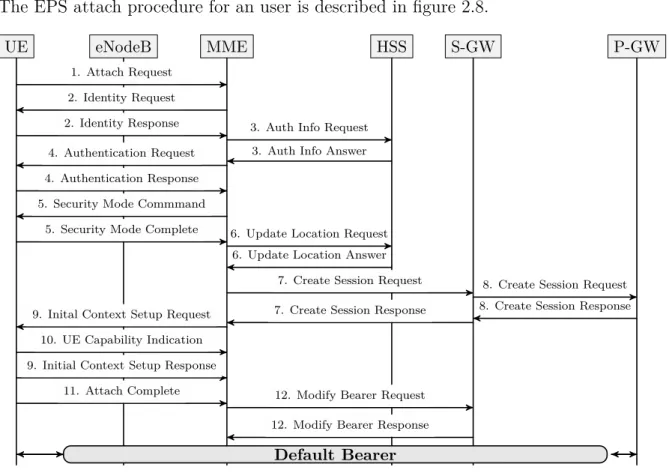
The EPS attach procedure for an user is described in figure 2.8.
P-GW S-GW HSS MME eNodeB UE 1. Attach Request 2. Identity Request
2. Identity Response 3. Auth Info Request 3. Auth Info Answer 4. Authentication Request
4. Authentication Response 5. Security Mode Commmand
5. Security Mode Complete 6. Update Location Request 6. Update Location Answer
7. Create Session Request 8. Create Session Request 8. Create Session Response 7. Create Session Response
9. Inital Context Setup Request 10. UE Capability Indication 9. Initial Context Setup Response
11. Attach Complete 12. Modify Bearer Request 12. Modify Bearer Response
Default Bearer
Figure 2.8: EPS attach procedure
1. The eNB forwards the Attach Request received by the UE in a S1-MME control message (Initial UE message) including the GUTI of the UE received from the last attach and the PDN connectivity request.
2. When the UE is unknown in the MME, the MME sends an Identity Request to the UE to request the IMSI. The UE answers with Identity Response (IMSI). 3. The MME sends an Authention Information Request message to the HSS,
re-questing AVs for the UE that the IMSI is known.
4. The MME sends an Authentication Request to the UE with the information (RAND and AUTN) to generate AV. The UE responds with RES. Upon the MME receives the message it compares the RES value generated by the UE and the XRES sent from the HSS, to authenticate the user.
5. After the user authentication is completed, the MME starts the NAS security setup procedure. The MME selects algorithms of ciphering and integrity received from the UE from the Attach Request message. After selecting the algorithms, it informs the UE by sending a Security Mode Command message. When the UE receives the message, it generates NAS security keys through the algorithms selected by the MME and executes an integrity validation. If the message passes the integrity check, the UE sends a Security Mode Complete to the MME to inform that NAS security was successfully generated.
6. The MME sends an Update Location Request message to the HSS, which includes the IMSI and MME ID, to register the UE and acquire the subscription information of the UE. The HSS registers the MME ID of the MME where the user is located. As response (Update Location Answer), the HSS sends the subscription information of the user. The subscription information permits the MME to create the EPS session and the default EPS bearer for the subscriber.
7. Now, all the information is available for the MME to set up the default EPS bearer. The MME begins by selecting a P-GW regarding the APN received from the HSS user subscription. The MME sends a Create Session Request to the S-GW, which includes relevant subscription information and destination P-GW. 8. The S-GW receives the message and sends it to the P-GW. This message includes a GTP tunnel endpoint. The P-GW creates a GTP tunnel endpoint and sends the Create Session Response to the S-GW, which includes the IP address allocated for the UE and QoS of the default bearer. When the S-GW receives the TEID from the P-GW, the S5/S8 bearer is established. The S-GW forwards the message to the MME and creates a GTP tunnel endpoint for the S1 bearer.
9. The MME updates the information related to the UE and sends it to the eNB through the Initial Context Setup Request message, such as the IP address allocated. After receiving the message, the GTP tunnel endpoint is created for the S1 bearer and the TEID is sent to the MME.
10. The UE sends all the details of its capabilities to the MME . 11. The eNB sends an Attach Complete message to the MME.
12. The MME updates the S1 bearer and sends the information via Modify Bearer Request message to the S-GW. And the S-GW sends an acknowledged to the MME. The bearer is now established
2.1.6 LTE implementation platforms
There are several open-source software-based platforms available, wherein each of them holds different characteristics and implementation, offering simulation or monitoring in real-time. The following sections describe some open-source solutions.
2.1.6.1 OpenLTE
OpenLTE is an open source implemention of the 3GPP LTE specifications. Its main focus is the transmission and reception of the downlink. However, the current goal is to expand the capabilities of the GNU Radio applications and inserting capabilities to a simple eNB application. These build a simple eNB in a straightforward EPC, written in Octave, C++ and Python.
In this project there is no UE implementation, and many features are undeveloped or unstable. Furthermore, it requires a huge amount of processing power and also, a very low latency. If there is any delay in the processing, the system will not respond in time and will lose samples [25].
2.1.6.2 srsLTE, srsUE, srsENB
srsLTE1 is an open source LTE library developed by Software Radio Systems2, written in C, following the 3GPP Release 10. Besides, this project is composed by srsUE and srsENB, written in C++. This library proposes a basic light-weight implementation of the EPC.
srsUE and srsENB are a complete software radio LTE UE and eNB, respectively, built on the srsLTE library. srsUE application presents all layers from PHY to IP. srsUE can connect to any LTE network and provides high-speed mobile connectivity through the standard interface. Transmiting and receiving radio signals are a requirement by a Software Defined Radio (SDR) like Ettus Research USRP. srsENB can connect with any EPC. When this connection occurs, a local LTE cell is created. Furthermore, this project uses some security functionalitis and NAS messages from OpenLTE project [26], [27].
2.1.6.3 OpenEPC
OpenEPC provides a full implementation of the EPC, following the 3GPP Release 8 to 12. The current version available, includes all the components that compose the
1srsLTE: https://www.srslte.com/
2Software Radio Systems: https://www.softwareradiosystems.com/
3GPP architecture including the interfaces with different access technologies and service platforms [28]. However, this implementation is not an open source solution.
2.1.6.4 NextEPC
NextEPC3 is an opensource implementation of the EPC of LTE networks supporting 3GPP Release 13. This project presents an implementation of the MME, HSS, S-GW, P-GW, and PCRF; however, it does not present any implementation of eNB neither UE, which is a limitation of testbed [29].
2.1.6.5 GR-LTE
GR-LTE is an open-source project, whose aim is to provide a modular environment for a LTE DL, reaching this by giving signal processing blocks into the GNU Radio framework. This implementation could be considered as an UE, and does not present a deployment of eNB or EPC [30].
2.1.6.6 Open-Source LTE Deployment (OSLD)
The OSLD aims are to provide open-source SDRs and shared deployment of software for wireless communications systems. The project consists on a modular LTE library for mobile terminals and base stations. Therefore, it uses the open-source SDR framework ALOE. This project was terminated and does not provide an implementation of the EPC [31].
2.1.6.7 AMARISOFT LTE
Amarisoft LTE4 is the most complete platform that implements 4G system, but it requires a paid license to use it. This platform provides LTE release 14 compliant EPC and eNB, Multimedia Broadcast Multicast Services (MBMS) gateway and IMS server. The EPC handles UE procedures such as, attach, authentication, radio bearer establishment,etc. The component of UE is developed in LTE release 8 support features up release 14, allowing simulation of hundreds of UEs. It also, provides a component of the 5G system, New Radio compliant release 15 [32].
2.1.6.8 OpenAirInterface (OAI)
OAI is an open-source platform developed to emulate 4G/5G networks following the 3GPP standards, written in C and C++. Initially, this project started to be developed by EURECOM5, but now it is managed by the OpenAirInterface Software Alliance (OSA)6. This platform offers a software-based implementation of the LTE network and it
3NextEPC: https://nextepc.com/
4Amarisoft LTE: https://www.amarisoft.com/ 5Eurecom: http://www.eurecom.fr/en
comprises the entire protocol stack of 3GPP standards both in E-UTRAN and EPC. Furthermore, it can be used to customize and build the 4G network (UE, eNB, and EPC) on a computer(Intel x86 processors).
Commercial UEs or OAI UEs can be connected to the OAI eNB to test distinct configurations and monitor the network in real-time. It also provides a hardware platform supporting drivers and firmware such as USRP, BladeRF, and EXMIMO board [33]–[35]. Moreover, it provides an environment with diverse of built-in tools such as soft monitoring and debugging tools, realistic emulation modes, protocol analyzer, and configurable logging system for all layers[35].
As mentioned before, the OAI is an implementation of the 3GPP specifications and provides a full implementation of the protocol stack. Figure 2.9 shows the LTE protocol stack implemented by OAI. According to [36], some features of the E-UTRAN are the integrity check and encryption using Advanced Encryption Standard (AES). Standards S1AP and GTP-U interfaces offer communication with the core network.
The EPC features are:
• reuses standards compliants of GTPv1u and GTPv2c protocols from the open-source software implementation of EPC namely nwEPC7.
• NAS integrity and encryption using AES.
• UE procedures handling: attach, authentication, service access, radio bearer establishment.
• transparent access to the IP network.
Figure 2.9: OpenAirInterface protocol stack (source [36]).
The OAI software is obtained from the Eurecom’s Gitlab and OpenAirInterface’s GitHub. It is on the Eurecom’s Gitlab where most information regarding this platform is provided8. This includes its tutorials, the software or hardware that they
recom-7nwEPC: https://sourceforge.net/projects/nwepc/
8OpenAirInterface5G-wiki: https://gitlab.eurecom.fr/oai/openairinterface5g/wikis/home
mend to use, the main configuration files that we need to modify, the recommended simulator/emulator that we need to use according to our objectives, among others.
Another recommendation of this community is regarding the code. OAI recommends to use the code of master branch instead of the development branch. The development branch consists of recently updated version code, and the master branch stable version of the code, updated once every 2-3 months. Furthermore, when the master branch is updated, a tagged release is created, and this tag consists of the latest stable.
This community is very active, and anyone can communicate through the mailing list. All the questions (problems, bugs discovery, doubts) published are visible for all subscribers allowing them to clarify other people with the same question.
The OAI source code splits into openairinterface5g9 (eNB RAN + UE RAN) and openair-cn10 (EPC), as represented in figure 2.10.
openairinterface5G
UE eNB
openair-cn
HSS MME S/P-GW
Figure 2.10: Brief representation of the modules implemented by OpenAirInterface
openairinterface5g
The openairinterface5g provides the source code for the UE and eNB RAN. The source code is organized in the following way11:
• cmake_targets: folder that contains the script to compile the code (simulation, emulation, and real-time platform) and the generated build output files.
• common/utils: OAI utilities, such as the Inter-task Interface (ITTI) • openair1: source code of PHY layer.
• openair2: implementation of the protocol stack of layer 2, such as RLC, MAC, PDCP, RRC and X2 Application Protocol (X2AP).
• openair3: implementation of the S1AP, NAS and GTPv1 for eNB and UE. • targets: top-level wrappers for unitary simulation for PHY channels, system-level
emulation and real-time eNB and UE.
The eNB needs a configuration file with specific parameters filled while it is running. The parameters of the configuration file are divided into six main sections [37]:
• Main parameters: configuration of the base station identity, Tracking Area Code (TAC), Mobile Country Code (MCC), and Mobile Netwok Code (MNC).
9OpenAirInterface5G: https://gitlab.eurecom.fr/oai/openairinterface5g 10Openair-cn: https://github.com/OPENAIRINTERFACE/openair-cn
• PHY parameters: configuration regarding the physical layers like frequency and band.
• Special Radio Bearer (SRB) parameters: configuration of the SRB like retrans-mission timer.
• MME parameters: configuration of the MME parameters like IP address.
• Network interfaces: configuration of the eNB S1 and S1-MME IP address and interface names.
• Log configuration: select the logger’s level and verbosity by taking all the layers and components of the network into account.
openair-cn
The openair-cn repository provides the source code for the main elements of the core network: S-GW, MME, P-GW, and HSS. The S-GW and P-GW integrate only one entity, the S/P-GW.
HSS is the network element that contains the database and uses freeDiameter12, an open-source protocol that implements the Diameter protocol. Moreover, it uses MySQL13 database to store all the information regarding the user subscriber. It needs some configurations regarding the access to the database, such as the username, password and database name. Besides, all the network subscribers need to be inserted into the database, including the IMSI, International Mobile Equipment Identity (IMEI), Mobile Station International Subscriber Directory Number (MSISDN). It is connected to MME via S6a thread.
MME also uses S6a thread like HSS. This also needs some configurations, such as maximum number of UEs and eNBs, S1AP outcome timer, the Globally Unique MME Identifier (GUMMEI) and the Tracking Area Identity (TAI) parameters, S11 and S1-MME interfaces, and logging.
S/P-GW is the combination of the elements S-GW and P-GW and do not com-municate through S5/S8 interface. It uses the GTP protocol to comcom-municate. A configuration file of this entity is also provided and is divided into S-GW and P-GW. The S-GW configuration refers to S11 and S1-U interfaces, ITTI message queue size and logging. The P-GW configuration is regarding the SGi interface, DNS address, and a pool of IP addresses available for UEs.
Despite being a very complete implementation, OAI is also a very complex system. The project presented is not well documented and organized, and code is sometimes confusing, which is hard for new users to understand or customize.
12freeDiameter: http://www.freediameter.net/ 13MySQL: https://www.mysql.com/
2.2 5G network
5G network has been designed to provide a more flexible and scablable network tech-nology, capable of connecting everyone and everything, everywhere. The first version of the 5G specifications system was introduced in release 15 by the 3GPP community, which includes the 5GC [38] and New Radio (NR) [39].
Initially, 3GPP community had some 5G architecture options where there were multiple possibilities for the core network architecture. The work had progressed, and only two main architectures were considered, shown in the figure 2.11.
5G NR 5GC
UE
(a) Standalone architecture with 5G core.
5G NR LTE eNB EPC Control Plane User Plane UE
(b) Non-standalone architecture with 5G NR
and LTE networks.
Figure 2.11: Main architecture options proposed by 3GPP for 5G evolution.
In figure 2.11a shows an architecture of the 5G NR with 5GC in Standalone (SA) mode. This architecture enables all the functionalities provided by the 5GC, like Service Based Architecture (SBA). Meanwhile, figure 2.11b shows the integration of the 5G radio systems in LTE networks, i.e., Non Standalone (NSA) mode. In this case, it uses LTE as the anchor for connection and connecting through the existing EPC. Only the user plane of the 5G radio is considered, which is then used with dual connectivity with LTE[40].
The 5G system is described to support data connectivity and services enabling deployments using new techniques such as Network Function Virtualization and Software Defined Networking. In order to allow independent scalability, evolution and flexible deployments, this new system maintains the principle of separating the Control Plane from the User Plane. Another principle for the design of 5G is to minimize the dependencies between the Access Network (AN) and the Core Network (CN) through the converged CN with a common interface (AN - CN) which integrates different access types such as 3GPP and non-3GPP access. 5G presents two options for the architecture:
(i) the first one is to be similar to LTE network namely reference points; (ii) the second consists of a service-based interface (SBI), which is used in the control plane, where it only exists one interface in network functions (NF), and these interfaces connect via bus.
2.2.1 Core netwok
The following sections describe the main functionalities of the 5G core network functions [38], [40], [41]. Figure 2.12 depitcs the non-roaming of the 5G network architecture where service-based interfaces are used into the control plane.
NEF NRF PCF UDM AF
AUSF AMF SMF
Nnssf Nnef Nnrf Npcf Nudm Naf
Nausf Namf Nsmf NSSF (R)AN UE UPF DN N1 Uu N2 N3 N4 N5 Control Plane Figure 2.12: 5G Architecture [38]
2.2.1.1 Access and Mobility Management Function (AMF)
AMF is responsible for termination of RAN control plane interface (N2) and NAS (N1), NAS messages ciphering and integrity protection, lawful intercept, registration management, connection, reachability and mobility, and Session Management Function (SMF) selection. It provides transport for session management (SM) messages between UE and SMF, transparent proxy for routing SM messages, access authentication and authorization, security anchor function (SEAF), security context management (SCM), and EPS bearer ID allocation for interworking with EPS. In addiction, the AMF supports functions associated with non-3GPP ANs like authentication of UEs connected over Non-3GPP InterWorking Function (N3IWF).
2.2.1.2 Session Management Function (SMF)
The SMF provides SM (session establishment, modification, release), allocation and management of the IP address to UEs, selection and control of User Plane Functions (UPF), termination of SM parts of NAS messages, control and coordination of charging
![Figure 2.2: Functional split between E-UTRAN and EPC (adapted from [11]).](https://thumb-eu.123doks.com/thumbv2/123dok_br/15791370.1078184/35.892.122.779.118.505/figure-functional-split-e-utran-epc-adapted.webp)
![Figure 2.4: Architecture of E-UTRAN (adapted from [11]).](https://thumb-eu.123doks.com/thumbv2/123dok_br/15791370.1078184/37.892.131.760.131.387/figure-architecture-of-e-utran-adapted-from.webp)
![Figure 3.1: LTE network elements implemented by OpenAirInterface [53].](https://thumb-eu.123doks.com/thumbv2/123dok_br/15791370.1078184/61.892.135.785.771.1059/figure-lte-network-elements-implemented-openairinterface.webp)