BlueLab IoT, a Universal Software Platform for IoT Data Acquisition
Devices
Vitor Vaz da Silvaab,
aDepartment of Engineering of Electronics, Telecommunication and Computers, ISEL/IPL - Instituto Superior de Engenharia de Lisboa, Portugal
bCTS-Uninova, Portugal vsilva @ deetc.isel.ipl.pt
Abstract1— Physical devices with different sensors and
sampling rates distributed over several unrelated locations need to store their values over time. Applications that need the result of a set of sensors must access their data. A common and simple interface within the physical devices, monitoring stations, to store data on a database is needed; as also a simple and common retrieval interface for any application that only shows the data as it is or processes it into higher levels of significance. BlueLab IoT is a platform with libraries and an interface application to aid that development; a working implementation is provided.
Keywords: IoT, database, station, device, storage, monitoring
I.INTRODUCTION
The expected number of IoT (Internet of Things) connected and accessed through the Internet is increasing day by day [1]. The applications covered by these devices are very diverse: simple fixed environmental sensors, home gadgets and appliances, industry modules, and mobile devices like wearables and transportation systems’ data. The ease with which these devices can be bought and installed also contributes to the increasing number of available IoTs including the young developers, students, hackers and curious self-learning individuals. The number of devices which are independent of any enterprise or government will increase likewise, and contribute to the Smart cities as shrubs in a forest.
Hardware and software on the devices and software on the server need a bridge that has to be built from both sides. This may be a difficult task for developers that are only focused on one of the sides of that bridge. To overcome that gap, this work provides such a bridge with a library on each end. This platform aims for data acquisition, monitoring, thus does not allow, at this stage, the possibility of acting upon the devices, even if there is an actuator on them.
The main purpose of this work is to build a universal platform that is simple, for immediate usage with minimal configuration; a plug and play type, which can also be used as a tool to develop other more complex approaches [2].
II.ARCHITECTURE
The BlueLab IoT architecture for data acquisition devices is presented in Figure 1. Each physical device can have
several sensors, and devices may differ among themselves. These devices communicate either directly with the server or they may communicate with a data gateway where after some processing the result is forwarded, relayed, to the server where it is stored. Each gateway can also be seen as a high level sensor and the data that it sends to the server is stored as if it had been collected by the gateway’s sensors. To use the platform each device or gateway that communicates with the server needs to create a session, which is done by a login with password and, after a successful authentication, receives a session id that must be used in all subsequent communications. Each session can be limited in time and or data volume, and when it expires a new connection must be established. There are two databases: user and data; one for user authentication and session validation and another where the data is stored. Physical devices are called stations and each data is stored as an entry. The database is implemented with PostgreSQL [3]. Different users have different schemas, i.e. each has its own database, this means that there is independency of data; two different users can have stations with the same station number.
Figure 1 – BlueLab IoT structure.
A. User
A user must register itself into the platform by email and password, where after a successful registration process can use the system. The user must create an environment, which is composed by all stations, and is the owner of that environment.
B. Station
A Station belongs to the user that created it and has a unique sequential number that is associated with it during the creation process where other information about the station is also stored as for example the station’s unique number (e.g.: mac address, imei, …), its latitude, longitude and height, a name and a description. A set of privileges define a station, delete protecting it, so that a specific station may or not be deleted along with all its entries, or if a range of entries can be deleted from that station.
C. Entry
The IoT data database’s entity-relation model is presented in Figure 2. It is the schema of a single user.
Figure 2 – BlueLab IoT data database Entity Relationship model
Regarding the entry entity shown in Figure 2, a data entry is a combination of a key-value pair, a key (kkey) and a value (vvalue) that is associated with it (e.g.: “temp”, 12.3) and, two date stamps, one indicating the time the sample was done (t_stamp) and, the other the time the value was stored in the database (db t stamp). These timestamps allow synchronization of data between stations, and their retrieval. Some stations, devices, may not have a real time clock (RTC) and their timestamp might be measured from the last reset. Different sensors may also have different sampling frequencies, digital filtering and eventually a temporal reference associated with it and stored as the t_stamp. An entry is identified by its increasing sequential number
seq_num within a specific station. The sequence number is
used for several reasons: to reference all key value pairs to the same sampling window time; as an acknowledge, as it is used as a result of storing the data value pairs and avoid repeating values if the device recovers from an error condition.
III.STATION
Each device used in this project is composed by an ESP8266-E12 embedded system with wifi [4], connected to all or eventually some of the following set of sensors: humidity, pressure and temperature sensor, BME280 [5], air quality sensor MQ135 [18, 19], and Real Time Clock DS3231. The sensors can also be switched off in each module during configuration right after the reset of the device. The software base is that of Arduino’s system [8].
The Arduino system has two top level functions, the setup() and the loop(). The setup is meant to be executed only once, and the loop is called repeatedly by the system.
Shown in Figure 3 is a detail of the setup code related to the BlueLab IoT library. The code shown does not handle error conditions, to make it easy to understand, and the access to the wifi is also not shown. A real implementation should handle error conditions, have a retry loop and
eventually make reset to the module if needed, as it is in the complete code available in links shown further down.
The setup code example shown in Figure 3 involves the creation of an object, dbConn, that handles all calls to the IoT data database. A login is then necessary, with the user e-mail and password, which corresponds to the registration process, which had to be done previously, and is described further down in the text. A successful login returns a session id which is then used on subsequent calls using the dbConn object. The actual sequence number is retrieved from the database and incremented for the next frame to be sent.
Figure 3 – Detail of the setup code of a device
Although not necessary it is a good idea to store in the database that the device has had a reset.
A frame with the reset condition, along with the time it occurred, is stored in the IoT data database. Any value can be associated with the “reset” key, for example indicating the reason or error code. There is no difference between a “reset” key and any other key (e.g. “abc213”) in the way it is processed and stored.
After the setup process where all the device’s configuration is made, the Arduino calls the loop() function repeatedly and the associated code is where the data is acquired and sent to the database.
A detail of that process is shown in the code of Figure 4, where all sensors are acquired with the same rate. It is a very simplistic approach and a real situation would preferably use
// create an object to access BlueLab dbConn = new DataBaseConnection(
login_host, login_url, data_host, data_url); // login in
dbConn->login(usr_email, usr_password); // get current sequence number
int seqNum=dbConn->getSeqNum(deviceId); // prepare next frame’s sequence number seqNum++;
// running the setup code means that // a reset has occurred in the device // store that information!
// ... get the time the reset occured long long tStamp=util.epochMicroseconds(); // ... build the frame
dbConn->newFrame(deviceId, seqNum, tStamp); // ... add the data to be stored
dbConn->addKeyValue("reset",0); // ... send the frame
dbConn->sendFrame();
// prepare next frame’s sequence number seqNum++;
interrupts. In either case, only the data that is available with the same timestamp (tStamp) should be on the same frame because all key values will have the same sequence number. On the other hand, if two different frames are sent with different timestamps and with the same sequence number they will be stored as long as the keys are different. This is helpful when it is necessary to relate and synchronize sampling events from sensors with different sampling times.
Figure 4 – Detail of the acquisition and storing code of a device
Each data value is identified by a key string and a value. To store data with the same sequence number but different timestamps it is necessary to build two different frames as shown in Figure 5.
Figure 5 – key-value pairs with same sequence number but different timestamps.
Devices need not be identical. The key-value pairs stored in the database can be specific to each device. If for example the same type of readings has to be made on a large area, it makes sense that the key strings be identical, even if the devices are not physically identical: i.e. two devices with different hardware both reading temperatures, can use the same key string “Temp”.
All calls are made through the https protocol by JSON format posts.
A station is in fact a set of sensors and a communication link to a database. So any other equivalent configuration can also be considered as a station. This project also uses the smartphone as a mobile station.
A. Mobile station
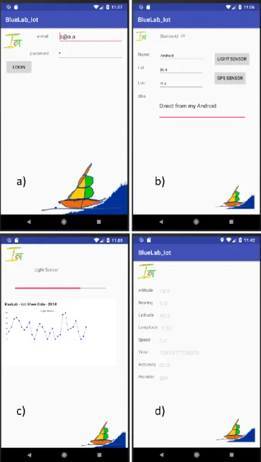
A smartphone has sensors that can be sampled and its values sent to the BlueLab IoT, this is achieved by using the same https calls as any other station. A simple application is shown in Figure 6.
Figure 6 – Smartphone BlueLab Iot application showing a) login b) station description c) light sensor ad d) GPS sensor
Figure 6 shows several sequences of the smartphone as a BlueLab IoT station. After a successful login a) the station is created automatically if it doesn’t exist and the user provides some information that is shown b), right after logging in. Then choosing the light sensor c) all light changes within a certain threshold are sent to the database. By choosing the GPS sensor d) a set of geospatial and speed information changing within certain thresholds are also sent to the database.
// New frame
dbConn->newFrame(deviceId, seqNum, tStamp); dbConn->addKeyValue("pressure", press); dbConn->addKeyValue("humi", humi); // Send the frame
dbConn->sendFrame()); // new Timestamp
other =util.epochMicroseconds();
// New frame – same seqNum different tStamp dbConn->newFrame(deviceId, seqNum, other); dbConn->addKeyValue("temp", temp);
dbConn->addKeyValue("air", airQual); // Send the frame
dbConn->sendFrame()); seqNum++;
// Get new values
float temp=bme.readTemperature(); int press=bme.readPressure(); float humi=bme.readHumidity(); int airQual=analogRead(sensorGas); tStamp=util.epochMicroseconds(); // Build a new frame
dbConn->newFrame(deviceId, seqNum, tStamp); // Add the values to the frame
dbConn->addKeyValue("pressure", press); dbConn->addKeyValue("humi", humi); dbConn->addKeyValue("temp", temp); dbConn->addKeyValue("air", airQual); // ... send the frame
dbConn->sendFrame();
// prepare next frame’s sequence number seqNum++;
IV.FUNCTIONS
Available functions for the hardware module can be downloaded from https://github.com/tektonia/bluelab iot where a working example can be uploaded to a compatible ESP8266-E12 hardware, or adapted for another microcontroller module with equivalent functionalities.
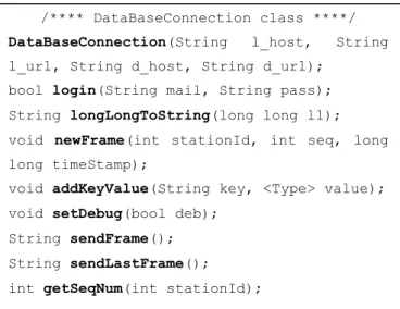
The BlueLab IoT functions available for the device are shown in Figure 7.
Most of these functions have been used in the code shown in Figure 3, namely: DataBaseConnection(), that creates a new object, and it is only needed to be done once in the program; login(), that establishes a connection with the User data system. It has to be called every time a session id is needed to access the IoT data database system; newFrame(), creates a new frame header with an empty data content header; addKeyValue(), adds key-value pairs to the data content of a frame; sendFrame(), sends a frame with the pre filled headers and content data header; getSeqNum(), returns the highest sequence number stored in the database for a specific station id.
Figure 7 – Functions available for the device
Of the functions listed in Figure 7 that have not been used in the examples shown are: setDebug(), that fills a debug header for all frames allowing a more verbose response from the calls made to the BlueLab IoT data database system; longLongToString(), which converts a long long data type value to a String; and sendLastFrame(), that resends the last frame with the most recent session id. This function is called specifically when the sendFrame() call fails due to an invalid or outdated session id. In that situation a new login has to be issued and after its success the sendLastFrame() function is called to send the outstanding frame.
Functions available for the API (application programming interface) software module can be found in https://github.com/tektonia/bluelab iot under the api folder. These functions are shown in Figure 8. All functions have the same $data parameter which corresponds to the contents of the post call made through the https protocol to https://bluelab.pt/iot/calliot.php; the only entry point interface to access the BlueLab IoT data database. It is expected that all the https calls have a valid e-mail and corresponding
session id before the functions of Figure 8 end up being called.
These functions allow the creation, destruction of the database, and the insertion and retrieval of data related to the IoT database represented in Figure 2.
Functions to change or remove a station definition, or delete data within a time range are available. Though, it is not possible to change the data acquired by a device. If a device changes place (latitude or longitude), then it is preferable to create a new station with the new position and an observation stating the changes and data is stored with the new station id.
Figure 8 – Functions available for the API
A working API that uses the functions shown in Figure 8 is presented in section V. Any user can build its own API by calling the required functions as shown in several examples on Figure 9, where javascript functions are called as they are in the html files on the BlueLab site.
/**** https post function calls ****/ function getAllStationIds($data);
/* Information of a specific station_id */ function getStation($data)
function getAllStations($data);
/* All entries from requested station_id and sequence number */
function getEntry($data)
/* All entries from requested station_id */ function getAllEntriesFromStation($data) /* Entry with the lowest sequence number of the requested station_id */
function getFirstEntry($data);
/* Highest sequence number entry of the requested station_id */
function getSeqNumber($data);
/* Stores a single key-value pair and its timestamp for the specified station_id and sequence number */
function storeKeyValue($data)
/* Stores an array of key-value pairs with the same timestamp for the specified station_id and sequence number */ function storeArrayKeyValue($data) /* Creates a new station with information supplied by the user */
function createStation($data) function createDataBaseIfNotExists($data) function createDataBase($data); function destroyDataBase($data); /**** DataBaseConnection class ****/
DataBaseConnection(String l_host, String l_url, String d_host, String d_url);
bool login(String mail, String pass); String longLongToString(long long ll); void newFrame(int stationId, int seq, long long timeStamp);
void addKeyValue(String key, <Type> value); void setDebug(bool deb);
String sendFrame(); String sendLastFrame(); int getSeqNum(int stationId);
Figure 9 – Javascript calls to the BlueLab IoT database functions
Examples in Figure 9 show the interaction with the https calls and processing its result. Function SeqNum() sends a request to the database and when it is processed, and its result is received through the function SeqNumReceived(data) defined as a callback function in SeqNum(); where data is a structure with the result of the call and data.seq_num holds the highest sequence number in the entries that belong to the station_id parameter in the getSeqNumber function call.
The main difference between newEntry() and multiEntry() is that the first only sends a key-value pair and the second an array of key-value pairs.
V.VALIDATION AND USE OF THE PROPOSED PLATFORM At the BlueLab IoT site https://bluelab.pt choose the IoT link on the IoT icon and a page will be displayed as shown in Figure 10, where it is possible to make a new registration, recover a forgotten one, or login in with the correct credentials.
a) b)
Figure 10 – BlueLab IoT a) entry page and links
The register process is to acquire a unique entry and identity into the system, with the e-mail as the user and a chosen password. If a new registration is not made, a demonstration login can be used instead (user: [email protected]
password: a); the state of that login depends only on those
that use it so no relevant information may be present on its associated database. Nevertheless some collected data is available to be used on the working examples as those below. After a successful login a page similar to that of Figure 11 shows up.
Figure 11 – Example showing the user environment and data to be requested
There are some clickable buttons, shown in Figure 11, that allow: to show all user stations (the environment), insert data into any station (as a debugging procedure, simulating the entry of device data, which is supposed to be added through the physical device interaction), and show data (download it as well) that can be visualized either as a scatter graph or on a map if the data holds geospatial information.
The selected selection shown in Figure 11 is to get data from 10/08/2018 20:00h till 11/08/2018 08:59h from stations 1,17,18, and 19 that hold the key “temp”. A dataset with 4 variables was received and shown as Figure 12.
function SeqNum(sid, statId){ $.post( "https://bluelab.pt/iot/calliot.php", {func: "getSeqNumber", email: $('#email').val(), sessionId: sid, station_id: statId }, SeqNumReceived, "json" ); } function SeqNumReceived(data){ seqNum = parseInt(data.seq_num)+1; } function newEntry(sid,st_id,seq,tm,ky,vl){ $.post( https://bluelab.pt/iot/calliot.php", { func: "storeKeyValue", sessionId: sid, email: $('#email').val(), station_id: st_id, seq_num: seq, t_stamp: tm, key: ky, value: vl }, newEntryCreated, "json" ); } function multiEntry(sid,st,seq,t,mx,mn,ac){ $.post( "https://bluelab.pt/iot/calliot.php", { func: "storeArrayKeyValue", sessionId: sid, email: $('#email').val(), station_id: st, seq_num: seq, t_stamp: t, dados: { tempMax: mx, tempMin: mn, tempAct: ac } }, multiEntryCreated, "json" ); }
Figure 12 – Temperature data in C from 4 different devices
The scatter graph of Figure 12 represents the temperature that similar stations acquired during the selected period. Stations 1,18 and 19 are similar as they were measuring room temperature in different places of a house, while station 17 was positioned outside the house in a shade so that it would not receive direct sunlight. Data in station 19 has a rhythmic modulation which is correlated to a continuous charging of a battery that is inside the physical device; the battery heats up while it charges. This station can be seen on Figure 13 a).
Figure 13 – Two different stations a) Rechargeable battery, temperature, humidity and pressure sensor and b) RTC, temperature, humidity, pressure
and air quality sensor.
Presented in Figure 13 are two different stations with the same microcontroller; station number 1 is on image b), it is continuously connected to a power source and has a real time clock, temperature, pressure, humidity and air quality
To try with a real example, upload the code supplied in https://github.com/tektonia/bluelab iot to an ESP8266-E12 module. The ssid and ssid_password for the wifi network must be set (and also the user e-mail and password) before compilation and uploading to the physical device; station.
VI.CONCLUSIONS
This system is easy to setup and made to work with the code supplied through the links available on previous sections. The current database [3] can hold up to 4 Tera byte of data. If this is an issue, data can be withdrawn from this database and stored somewhere else, eventually not storing the raw data but statistical outputs. A developer user of the BlueLab IoT can build its own API with the functions provided above, and install any quantity of different stations (maximum set as 25).
Using a mobile station with geolocation for example a smartphone, which stores the path to BlueLab Iot, and another station, carried along with the smartphone, that sends temperature values, allows the temperature to be geo-synchronized.
Future developments like a sophisticated representation for the visualization of the data, including statistic information will be available in the BlueLab Iot site; one of the basic requirements of the IoT elements [9].
REFERENCES
[1] T. Kramp, R. van Kranenburg, and S. Lange, “Introduction to the internet of things,” in Enabling
Things to Talk: Designing IoT Solutions with the IoT Architectural Reference Model, 2013.
[2] M. Bauer et al., “IoT reference architecture,” in
Enabling Things to Talk: Designing IoT Solutions with the IoT Architectural Reference Model, 2013.
[3] PostgreSQL, “PostgreSQL: The world’s most
advanced open source database,”
http://www.postgresql.org/, 2014. .
[4] Espressif, “ESP8266EX Overview | Espressif Systems,” Esp8266, 2017. .
[5] Bosch Sensortec, “BME280 - Combined humidity, pressure and temperature sensor,” Datasheet. 2015. [6] K. Vandana, C. Baweja, Simmarpreet, and S.
Chopra, “Influence of Temperature and Humidity on the Output Resistance Ratio of the MQ-135 Sensor,”
Int. J. Adv. Res. Comput. Sci. Softw. Eng., 2016.
[7] X. Liu, S. Cheng, H. Liu, S. Hu, D. Zhang, and H. Ning, “A Survey on Gas Sensing Technology,”
Sensors, 2012.
[8] Arduino, “Software Arduino (IDE),” Arduino, 2017.
[Online]. Available:
https://www.arduino.cc/en/Guide/Environment. [9] A. Knud and L. Lueth, “IoT basics : Getting started