Lorena Matildes Assunção da Silveira
Licenciada em Ciências da Engenharia Civil
Design Philosophy Study on CFRP RC Structures
Dissertação para obtenção do Grau de Mestre em
Engenharia Civil - Perfil de Estruturas
Orientador: Dr.-Ing. Maria Patricia Garibaldi, Research Associate, Institute of Concrete Structures - Technische Universität Dresden
Co-orientadores: Professor Doutor Carlos M. Chastre Rodrigues, Professor Auxiliar, Faculdade de Ciências e Tecnologia,UNL
Dr.-Ing. Frank Jesse, Investigador,Hentschke Bau GmbH.
Júri:
Presidente: Prof. Doutor Armando Manuel Sequeira Nunes Antão Arguente: Doutor Hugo Emanuel Charrinho da Costa Biscaia
Vogal: Prof. Doutor Carlos M. Chastre Rodrigues
Design Philosophy Study on CFRP RC Structures
Copyright © Lorena Matildes Assunção da Silveira, Faculdade de Ciências e Tecnologia, Universidade Nova de Lisboa.
Acknowledgments
I would like to thank all who in one way or another contributed in the completion of the present dissertation. First, I give thanks to God for being present in my life, for protecting and giving me strength to make it through every day.
I would like to express my deepest gratitude to my advisors, Dr.-Ing. Maria Patricia Garibaldi, Technische Universität Dresden- Faculty of Civil Engineering, Dr. -Ing. Frank Jess, Technische Universität Dresden- Faculty of Civil Engineering and Dr.-Ing. Carlos Chastre, Universidade Nova de Lisboa- Faculdade de Ciências e Tecnologia for their continuous guidance and support.
Lastly, I must thank my family for their love and unfailing support, I thank my father and my grandmother for their constant words of encouragement, my friends Priscilla and Miguel, my sisters Barbara and Maria Clara for their patience and willingness to help me at any stage of this dissertation and specially my mother who continuously supports and encourages me and my decisions. This accomplishment would not have been possible without them. Thank you.
Abstract
The present dissertation was developed with the main purpose of comparing the different design philosophies existing for prestressed reinforced concrete members, as well as analyzing a solution that is both safe and economically viable.
Since one of the major problems in civil engineering infrastructures is due to corrosion, a study was conducted to examine the feasibility of replacing the material used as reinforcement and prestress. The steel, which for many decades has been used shall be replaced by FRP, particularly CFRP. However, since carbon presents a brittle behavior, a new design methodology suggested by fib and by the Canadian code is presented so that the failure is not due to the reinforcement but due to the concrete, which, although it is not a ductile material, presents more ductility than materials with carbon fibers. In this way, a code has been developed so that, through the balance of the cross section, it calculates the amount of reinforcement required, following the American (ACI) and European code (Eurocode) design methodology. Another code for prestressed reinforced concrete members was elaborated to analyze the prestress system used and the material used as reinforcement and tendons.
The European code has proved to be economically viable since, for the same applied moment, it requires a smaller amount of reinforcement. As for the bonded and unbonded system the results show that the systems with unbonded tendons are only feasible when the concrete members are subjected to high moments. It is also observed that depending on the initial force applied on the prestress, the results may be favorable regarding to the amount of reinforcement required, however the amount of reinforcement can be significantly increased when the initial force of the prestress is highly increased.
Keywords: Reinforced concrete, Ultimate limit state, ACI, Eurocode, CFRP, Bonded and unbonded
Resumo
A presente dissertação foi elaborada com o principal objectivo de comparar as diferentes filosofias de dimensionamentos existentes para peças de betão armado pré-esforçado, bem como analisar uma solução que seja ao mesmo tempo, segura e economicamente viável.
Uma vez que um dos principais problemas nas infraestruturas de engenharia civil, ocorre devido a corrosão. Foi elaborado um estudo para analisar a viabilidade de substituição do material usado como armadura ordinária e cabos de pré-esforço. O aço, que por muitas décadas vem sendo usado, passa a ser substituído por FRP, nomeadamente CFRP. No entanto, uma vez que o carbono apresenta um comportamento frágil, uma nova metodologia de dimensionamento sugerida pela FIB é apresentada, para que a rotura não se dê pela armadura ordinária, mas sim pelo betão, que mesmo não sendo um material dúctil, apresenta mais ductilidade que os elementos feitos com fibras de carbono.
Deste modo, foi elaborado um código que através do equilíbrio da secção transversal, calcula a quantidade de reforço necessária através da metodologia de dimensionamento do código americano (ACI) e do código Europeu (Eurocódigo). Um segundo código foi elaborado para peças de betão armado pré-esforçadas para analisar o sistema mais adequado para o pré-esforço, bem como o material mais vantajoso.
O código europeu mostrou-se economicamente mais viável, uma vez que para o mesmo momento fletor requer uma menor quantidade de armadura. Quanto ao sistema aderente e não aderente os resultados mostram que os sistemas com pré-esforço não aderente só são viáveis para um momento atuante muito elevado. Observa-se também que, dependendo da força inicial que aplicamos no pré-esforço, os resultados podem ser bem vantajosos relativamente a quantidade de armadura necessária, mas, no entanto, pode aumentar significativamente a quantidade de reforço necessário quando aumentamos em demasia a força inicial aplicada nos cabos.
Palavras-chave: Betão Armado, Estado Limite Último, ACI, Eurocódigo, CFRP, Sistema de
Table of Contents
Acknowledgments ... iii
Abstract...v
Resumo ... vii
Table of Contents ... ix
List of Figures ... xi
List of Tables ... xv
Abbreviations and Symbols ... xvii
1 Introduction ... 1
1.1 Objectives and Scope ... 1
1.2 Thesis outline ... 1
2 Design philosophy... 3
2.1 ACI 314 & ACI 318 flexure design philosophy ... 3
2.1.1 Design concrete compressive strength ... 4
2.1.2 Design flexural tensile strength of steel... 6
2.1.3 Design procedure ... 6
2.1.4 Safety factors ... 10
2.1.5 Load combinations ... 11
2.2 Eurocode 2 ... 12
2.2.1 Design compressive strength of concrete ... 13
2.2.2 Design flexural tensile strength of steel... 14
2.2.3 Safety factors ... 14
2.2.4 Design procedure ... 15
2.3 Comparison- ACI codes and Eurocode 2 ... 19
3 Prestressed reinforced concrete members ... 21
3.1 Prestress history ... 21
3.2 Prestress systems ... 23
3.4 Unbonded tendons ... 27
3.5 FRP ... 28
3.5.1 FRP Structures ... 30
3.6 Ultimate limit state ... 33
3.6.1 Compression force ... 33
3.6.2 Prestress force ... 33
3.6.3 Materials ... 36
3.6.4 ULS – Flexural Verification ... 37
4 Parametric study for optimization of RC structures in bending with CFRP ... 39
4.1 General considerations ... 39
4.2 The code developed ... 39
4.2.1 Properties of materials ... 42
4.3 ACI 314/318 vs Eurocode 2 analysis ... 46
4.3.1 Case A - ACI 318 and Eurocode 2 design procedure ... 49
4.3.2 Case B - Eurocode 2 and ACI 318 with Eurocode parameters ... 52
4.3.3 Case C- ACI procedure and the effect of the ultimate strain ... 53
4.3.4 Case D- ACI comparison for effect of the safety factor ... 55
4.4 Analysis of prestressed reinforced concrete members ... 56
4.5 Bonded vs Unbonded tendons - Case 1 ... 59
4.6 Bonded vs Unbonded tendons - Case 2 ... 63
4.7 Bonded tendons ... 64
4.8 Unbonded post tensioning ... 67
4.9 Influence of the initial prestress in the amount of reinforcement ... 70
4.10 New design approach ... 72
5 Conclusions ... 75
References ... 77
List of Figures
Figure 2.1 - Stress-Strain curve for concrete adapted from ACI [6] ... 5
Figure 2.2 – Parabolic-rectangular stress-strain curve for concrete adapted from ACI [6] ... 5
Figure 2.3 - Stress-strain curve for steel adapted from ACI [7] ... 6
Figure 2.4 - Internal stress and strain distribution for a rectangular section under flexure at ULS;(a) Cross Section; (b) Strain Diagram; (c) Parabola-rectangular stress block; (d) bilinear stress block; (e) Rectangular stress block. Adapted from ACI [7]. ... 7
Figure 2.5 - Rectangular stress block considering compression reinforcement [8] ... 7
Figure 2.6 - Strength reduction factor ACI 318 [2] ... 11
Figure 2.7 - Parabola-rectangle stress-strain diagram for concrete under compression [4] ... 13
Figure 2.8 - Parabola-rectangle, bilinear and rectangular stress block adapted from Eurocode 2 [4] . 14 Figure 2.9 - Idealized and design stress-strain diagrams for reinforcing steel[4] ... 14
Figure 2.10 - Stress distribution when the reinforced concrete member is subjected to bending moment [10] ... 15
Figure 2.11 – Stress block considering compression reinforcement [11] ... 16
Figure 3.1 - Prestressed wooden bridge as designed by Stephen H. Long [12] ... 21
Figure 3.2 - Prestress cast iron sidewalk as designed by Peter H. Jackson-Diagrams[12] ... 22
Figure 3.3 - Prestress cast iron sidewalk as designed by Peter H. Jackson- [12] ... 23
Figure 3.4 – (a) Concrete member subjected to bending without prestress; (b) concrete member subjected to bending with prestress- tensile strength reduction[13] ... 24
Figure 3.5 - Prestress systems ... 24
Figure 3.6 - Prestress systems: (a) pre-tensioning; (b) post-tensioning [14] ... 25
Figure 3.7 - Process for the manufacture of a bonded prestressed RC beam with post tension system (a) Placing prestress cables, (b) Concreting and hardening of concrete, (c) Anchoring process, (d) Grouting process, (e) Hardening of the concrete beam, (f) Anchoring detail [15] ... 26
Figure 3.8 - Cross-section of wire unbonded tendon ... 27
Figure 3.9 – Tensile strength comparison for different materials [17] ... 29
Figure 3.10 – Bond type anchorage system [18]... 30
Figure 3.11 - Lunenshe Gasse Bridges [20]... 30
Figure 3.13 – The Beddington Bridges Trail, Canada [21] ... 31
Figure 3.14 - Strain distribution for prestressed concrete beam ... 35
Figure 3.15 - Internal forces for calculation of the cross-section resistance capacity ... 37
Figure 4.1 - Flowchart of the cycle performed by VBA code ... 41
Figure 4.2 - Applied load, shear and bending moment diagrams ... 47
Figure 4.3 - Cross section and stress- strain distribution adapted from EC2 considering failure due to concrete crushing [4] ... 48
Figure 4.4 - Cross section and stress- strain distribution adapted from ACI considering failure due to concrete crushing [7] ... 48
Figure 4.5 - Results for ACI [1] and Eurocode [4] design with the Portuguese National Annex (PT) and with the German one (DE); (a) Amount of reinforcement required with the variation of the applied moment; (b) Depth of the neutral axis and level arm varying the applied moment; (c)Strain distribution with the variation of the applied moment; (d) Nominal moment varying the nominal moment ... 50
Figure 4.6 - Difference between ACI and Eurocode changing the procedure of the design. Amount of reinforcement required ... 53
Figure 4.7 - Results for variation of the ultimate limit strain. ACI procedure considering the bilinear (bili) stress block. (a) Amount of reinforcement required; (b) Strain distribution ... 55
Figure 4.8 - Variation of the safety factor. ACI design. (a) Amount of reinforcement required; (b) Strain distribution ... 56
Figure 4.9- Prestressed RC beam- Steel rebar and steel tendons ... 57
Figure 4.10 – Prestressed RC beam - Steel rebar and CFRP tendons ... 57
Figure 4.11- Prestressed RC beam - CFRP rebar and carbon tendons ... 58
Figure 4.12 – Prestress configuration, loads and diagrams ... 58
Figure 4.13 - Comparison for steel rebars and tendons varying the applied bending moment ... 60
Figure 4.14 - Comparison for steel rebars and CFRP tendons varying the applied bending moment . 61 Figure 4.15 - Comparison for CFRP rebars and tendons varying the applied bending moment ... 62
Figure 4.16 - Comparison for steel rebars and tendons varying the width ... 63
Figure 4.17 - Comparison for steel rebars and CFRP tendons varying the width ... 63
Figure 4.18 - Comparison for CFRP rebars and tendons varying the width ... 64
Figure 4.20 - Comparison of bonded tendons. Effectiveness of steel tendons and rebars compared to CFRP tendons and rebars ... 66 Figure 4.21 - Comparison of unbonded tendons. Effectiveness of steel tendons and rebars compared
to carbon tendons ... 68 Figure 4.22 - Comparison unbonded tendons. Effectiveness of steel tendons and rebars compared to
List of Tables
Table 2.1 – Concrete stress block parameters given by ACI [9] ... 8
Table 2.2 – Load combinations ... 11
Table 2.3 - Stress-strain distribution for concrete crushing and steel failure ... 15
Table 2.4 - ACI and EC2 design comparison ... 19
Table 3.1 - CFRP Bridges examples ... 32
Table 3.2 - Steel and carbon. Comparison of stress-strain curves ... 36
Table 3.3 - Material safety factors given by FIB[5] and EC2 [4] ... 37
Table 4.1 – Properties of CFRP tendons ... 42
Table 4.2 – Properties of steel tendons ... 42
Table 4.3 - Properties of CFRP rebars ... 43
Table 4.4 - Properties of CFRP rebars ... 43
Table 4.5 – Geometry of the cross section for case 1 ... 44
Table 4.6 – Concrete properties for case 1 ... 44
Table 4.7 – Table used to choose the type of prestress system, tendon material, rebar material and concrete strength class for case 1 ... 45
Table 4.8 - Geometry of the cross section for case 2 ... 45
Table 4.9 - Concrete properties for case ... 45
Table 4.10 - Table used to choose the type of prestress system, tendon material, rebar material and concrete strength class for case 1 ... 46
Table 4.11 - Assumptions, case A ... 49
Table 4.12 - Assumptions, case B ... 53
Table 4.13 - Assumptions, case C ... 54
Table 4.14 - Assumptions, case D ... 55
Abbreviations and Symbols
Abbreviations
EC2 Eurocode 2
ACI American Concrete Institute RC Reinforced Concrete
FRP Fiber Reinforced Polymers
CFRP Carbon Fiber Reinforced Polymers VBA Visual Basic for Applications
Symbols
𝐴𝐸𝑑 Design value of an accidental action and 𝐴𝐸𝑑 = 𝛾1𝐴𝐸𝑘
𝐴𝐸𝑘 Characteristic value of seismic action
𝐴𝑝 Area of a prestressing tendon or tendons
𝐴𝑠 Area of tension steel reinforcement
𝑏 Width
𝑑 Effective depth of a cross-section
𝐸 Effect of actions
𝐸𝑑 Design value of effect of actions Ef Modulus of elasticity of FRP
𝐸𝑝 Modulus of elasticity of tendons
𝐸𝑠 Modulus of elasticity of reinforcement
fcd Design concrete strength
fck Characteristic compressive cylinder strength of concrete at 28 days
Fp Prestress force
Fc Compression force according to EC2
C Compression force according to ACI
𝑓𝑓𝑑 Design value of tensile strength for FRP
𝑓𝑓𝑘 Characteristic value of tensile strength of FRP reinforcement
𝑓𝑝𝑘 Characteristic tensile strength of prestressing
fy Yield strength of reinforcement fyd Design yield strength of reinforcement fyk Characteristic yield strength of reinforcement
f‘c Concrete strength
𝐺𝑗𝑘 Characteristic value of permanent action j
ℎ Overall depth of a cross-section
𝑃∞ Prestress force after all losses
𝑄1𝑘 Characteristic value of the leading variable action
𝑀𝐸𝑑 Design moment
𝑀𝑅𝑑 Resistant moment
x Depth of the neutral axis
ΔPc+s+r Long term losses due to creep, shrinkage and relaxation at location x, at time t
𝜀𝑐𝑢 Ultimate compressive strain in the concrete
𝜀𝑝0 Initial strain of tendon
𝜀𝑐 Compressive strain in the concrete
𝜀𝑐𝑢2 Ultimate compressive strain in the concrete according to Table 3.1 EC2
𝜀𝑐2 Strain at reaching the maximum strength according to Table 3.1 EC2
𝜀𝑠 Steel strain
𝜀𝑝 Prestress strain
𝜀𝑢𝑘 Characteristic strain of reinforcement or prestressing steel at maximum load
𝛾𝑐 Partial factor for concrete
𝛾𝑓 Partial factor for FRP
𝛾𝑝 Partial factor for tendons
1
Introduction
1.1
Objectives and Scope
Textile reinforced concrete, carbon concrete composites or CFRP RC are different names for the same type of modern development. The use of high performance fibers as a replacement for reinforcement steel. Among the advantages are the high strength, high durability, excellent fatigue resistance, a principal non-corrosive characteristic and more. Barriers for practical application include high price, required adaptation of production technology and also lack of experience in practical design or lack of design rules itself. One of the most promising materials as a replacement for steel are carbon fibers. The economic aspect of design solution is strongly connected to the required amount of reinforcement and the security factor. The use of high safety factor leads to expensive infrastructures. A conservative approach might be as safe as uneconomic. The blind transfer of RC design rules to Carbon fiber reinforcement might be as simple as unsafe, because the switch from ductile steel reinforcement to brittle carbon fibers will have fundamental impact on the load bearing behavior and especially on the observable failure types. For design with CFRP various guidelines and recommendations exists already, but they differ fundamentally in the numbers chosen for safety factors and safety concepts. The aim of this study is to show the impact on design results caused by using different design concepts and to create a conceptual design for both the structures described above and the elements to be used.
1.2
Thesis outline
The presented thesis is divided into five chapters.
Chapter 1: Theme Description, previously developed work, motivations and objectives to be achieved
with the realization of this work.
Chapter 2: The design theory for reinforced concrete structures according to the American and
European code. Comparison between the different approaches for the flexural design in the ultimate limit state.
Chapter 3: History of prestress and its different systems. The influence of the choice of types of tendons,
whether bound or unbound. Physical and mechanical characteristics of the material used for the ultimate limit state. Introduction to a new design theory suggested by fib.
Chapter 4: Presenting the results obtained with the help of VBA program. Comparison in the amount of
reinforcement needed when using the American or European approach. Comparison between bonded and unbonded tendons and also carbon tendons and rebars. Effect of the initial prestress force for a prestressed rectangular section of reinforced concrete.
2
Design philosophy
The aim of this study is to understand and compare the different approaches based on the ACI 318 and ACI 314 [1-3] and the Eurocode 2 [4] The principles adopted for both codes are the same, the concrete member must be in equilibrium, which means that the internal forces must balance the external load. However, they present differences in the design procedure which leads to significant differences in the results for reinforced concrete structures in bending.
For prestressed reinforced concrete structures another comparison is made, and different types of reinforcement and prestress are used.
Once one of the most important aspect of this study is to evaluate the feasibility of CFRP structures, and since the Eurocode does not provide a design procedure for this type of material and so, for the conventional steel prestressed structure the EC2 was followed and for CFRP ones the design procedure given by FIB [5] was followed.
In this chapter are described the procedures given by the previously-mentioned codes and different assumptions are considered to evaluate where these differences come from.
2.1
ACI 314 & ACI 318 flexure design philosophy
The approach suggested by the ACI [2] is that there is a reduction in the resistant moment and not a reduction of the capacities of the material. Differently than suggest by Eurocode 2 [4]
To calculate the resistant moment, i.e. the design strength of a given cross section, the considered assumptions are:
• Bernoulli hypothesis, plan sections remain plans after loading. The strain in concrete and reinforcement is assumed to be directly proportional to the distance from the neutral axil. Linear strain distribution;
• The static equilibrium and the strain compatibility must be satisfied;
• Stress in reinforcement below the yield point shall be taken as the strain times the modulus of elasticity, Es linear behavior. For strains, greater than that corresponding to εy, stress is considered as fy;
• For the flexural calculation, the tensile strength of concrete is neglected;
• Concrete strength = f’c;
• Yield strength of reinforcement = fy;
2.1.1
Design concrete compressive strength
Figure 2.1 - Stress-Strain curve for concrete adapted from ACI [6]
Figure 2.2 – Parabolic-rectangular stress-strain curve for concrete adapted from ACI [6]
To calculate the stress of the concrete curve (Figure 2.2) the equation shown in the expression (12) must be used:
𝑓𝑐= {
0.85
𝑓′
𝑐[2
(Ɛ𝑐
Ɛ𝑐2)
−
(Ɛ𝑐
Ɛ𝑐2) 2
]
𝑓𝑜𝑟 0 ≤ Ɛ𝑐 ≤ Ɛ𝑜
0.85
𝑓′
𝑐𝑓𝑜𝑟 Ɛ𝑜≤ Ɛ𝑐≤ Ɛ𝑐𝑢
2.1.2
Design flexural tensile strength of steel
For the steel used as reinforcement the following behavior of the material was considered (Figure 2.3). It presents an initial linear branch that satisfies the Law of Hook and after reaching the point of yield, the stress remains constant on a horizontal plateau.
Figure 2.3 - Stress-strain curve for steel adapted from ACI [7]
2.1.3
Design procedure
Figure 2.4 (d). This code also presents a simplification, the rectangular stress block due to its easy calculation process. Figure 2.4(e).
Figure 2.4 - Internal stress and strain distribution for a rectangular section under flexure at ULS;(a) Cross Section; (b) Strain Diagram; (c) Parabola-rectangular stress block; (d) bilinear
stress block; (e) Rectangular stress block. Adapted from ACI [7].
When the compression reinforcement is considered the following scheme is adopted, (Figure 2.5) and therefore, the compression force given by the reinforcement helps the compression force given by the concrete. The tensile force must balance both forces, the concrete and the steel ones.
Figure 2.5 - Rectangular stress block considering compression reinforcement [8]
However, for this case, it was considered a reinforced concrete member under flexure and compression reinforcement were not included in the equilibrium.
For a singly reinforced rectangular beam, an initial strain is always assumed for the concrete and steel. Knowing the initial strain, it is possible to calculate the depth of the neutral axis that satisfies the balanced strain condition through the following expression:
𝑥 = 𝜀 𝜀𝑐
𝑐+ 𝜀𝑠∙ 𝑑 (2)
where:
𝑥 is the depth of the neutral axis;
𝜀𝑐 is the concrete strain;
𝜀𝑠 is the steel strain;
𝑑 is distance from extreme compression fiber to centroid of tension reinforcement;
By calculating through the numerical integration the stress block diagram, it is possible to obtain the resulting compression force, 𝐶:
𝐶 = 0.85𝑓𝑐′𝛼𝑏 (3)
where :
f'c is specified compressive strength of concrete; b is the width of rectangular cross section; α = x∙ β1;
β1- reduction coefficient obtained from the following parameter table (Table 2.1) provided by ACI [9]
Table 2.1 – Concrete stress block parameters given by ACI [9]
f’c [MPa] ≤8 35 42 49 ≥56
α 0.72 0.68 0.64 0.60 0.56
β 0.425 0.400 0.375 0.350 0.325
β1 0.85 0.8 0.75 0.7 0.65
γ = α/ β1 0.85 0.85 0.85 0.86 0.86
To satisfy the equilibrium condition the internal forces must balance, hence it is possible to write the following expression:
Where:
C is the resulting compression force given by equation (2) T is the tensile force of reinforcement given by:
𝐹𝑠= 𝐴𝑠𝑓𝑦 (5)
Where:
𝐴𝑠 is the area of tension steel reinforcement;
𝑓𝑦 is the specified yield stress of non-prestressed steel reinforcement;
Thus, it is possible to write the following expression:
𝐴𝑠𝑓𝑦= 0.85𝑓𝑐′𝛽1𝑥𝑏 (6)
Thus, introducing Eq. (2) and Eq. (4) into Eq. (3) the following expression can be derived and therefore it is possible to obtain the necessary amount of reinforcement, 𝐴𝑠:
𝐴𝑠=0.85𝑓𝑐 ′𝛽
1𝑥𝑏
𝑓𝑦 (7)
The nominal moment is the capacity of the structure to resist the applied loads and it can be calculate by the internal forces of the cross section, as can be seen in the following expression:
𝑀𝑛= 𝐴𝑠𝑓𝑦(𝑑 −𝛽12 )𝑥 (8)
Once the nominal moment has been calculated, the reduction factor is applied and the following condition must be satisfied:
𝑀𝑢≤ 𝜙𝑀𝑛 (9)
Where:
𝜙 is the reduction factor;
𝑀𝑛 is the nominal moment capacity;
𝑀𝑢 is the factored moment at section;
𝐶𝑡 =𝑓𝑐 ′∙ 𝑏 ∙ 𝑥
𝑡
2 (10)
Where 𝑥𝑡 represents the compressed zone until it reaches 𝑓𝑐′.
Regarding the application point of the force, as it is known, the resulting force on the triangular part, before the concrete strain reaches the ultimate strain, is applied to a third of the extreme compression fiber (𝑐𝑡/3). On the other hand, the constant part of the stress, after the strain reaches its ultimate point,
is calculated in the same way the resulting force is applied in the middle of the stress block.
After the calculation of the resulting compression force and the point of application for the linear stress block, it is possible to calculate the nominal moment by the following equation (10) and thus proceed to check the ultimate limit state through equation (8).
𝑀𝑛 = 𝐶𝑡∙ 𝑧𝑡∙ 𝐶𝑟∙ 𝑧𝑟 (11)
Where:
𝐶𝑡 is the resulting compression force before the ultimate strain is reached;
𝑧𝑡 is the distance between the force resulting from the triangular stress block and the tensile force;
𝐶𝑟 is the resulting compression force after the ultimate strain is reached;
𝑧𝑟 is the distance between the force resulting from the rectangular stress block and the tensile force;
For the present study, the bilinear scheme has been used and it does not include compression reinforcement.
2.1.4
Safety factors
Figure 2.6 - Strength reduction factor ACI 318 [2]
Where:
• Compression-controlled: Φ= 0.65
• Tension-controlled: Φ = 0.90
• Transition zone: Φ = 0.65 + (εsy – 0.002) (250/3)
2.1.5
Load combinations
According to ACI [2] the load combinations considered are presented in Table 2.2 and the required strength should be bigger than the factored loads.
Table 2.2 – Load combinations
Loading combination Primary load
U = 1.4D D
U = 1.2D + 1.6L + 0.5(Lr or S or R) L
U = 1.2D + 1.6(Lr or S or R) + (1.0L or 0.5W) Lr or S or R U = 1.2D + 1.0W + 1.0L + 0.5(Lr or S or R) W
U = 1.2D + 1.0E + 1.0L + 0.2S E
U = 0.9D + 1.0W W
U = 0.9D + 1.0E E
Where :
U = the design (ultimate) load D = dead load
F = fluid load
T = self straining force L = live load
Lr = roof live load
H = lateral earth pressure load, ground water pressure. S = snow load
R = rain load W = wind load E = earthquake load
2.2
Eurocode 2
Contrary to what is provided by the ACI code,presented in the previous section, the Eurocode 2 is not based on reducing the bearing capacity of the reinforced concrete member but on the contrary, the resistant moment is already calculated with the reduced capacities of the materials that are affected by a safety factor.
To calculate the resistant moment, design strength, of a given cross section the assumptions considered are:
• Bernoulli hypothesis, flat sections remain flat after loading. The strain in concrete and reinforcement is assumed to be directly proportional to the distance from the neutral axis. Linear strain distribution;
• The static equilibrium and the strain compatibility must be satisfied;
• Stress in reinforcement below the yield point shall be taken as the strain times the modulus of elasticity, linear behavior. For strains, greater than that stress, is considered as fyd ;
• For the flexural calculation, the tensile strength of concrete is neglected; • Design concrete strength = fcd ;
• Design yield strength of steel reinforcement = fyd;;
2.2.1
Design compressive strength of concrete
• Stress-strain relationship for the design of the cross section
According to EN-1992-1-1 (3.1.7) there are three options for the stress-strain distribution and stress block: (1) Parabola-rectangle, Figure 2.7; (2) Bi-linear and (3) Rectangular. The stress-strain distribution that has been used in this thesis is the parabola-rectangle as shown.
Figure 2.7 - Parabola-rectangle stress-strain diagram for concrete under compression [4]
In which the design value of concrete compressive strength is given by the following expression:
𝑓𝑐𝑑= 𝛼𝑐𝑐𝛾𝑓𝑐𝑘
𝑐 (12)
Where:
𝛾𝑐 is the partial safety factor for concrete;
αcc is the coefficient taking account of long term effects on the compressive strength and of unfavorable effects resulting from the way the load is applied.
The value of αcc can be found in the National Annex and therefore it is considered as 0.85 in the German Annex and 1.0 in the Portuguese Annex.
The curve shown in Figure 2.7 can be obtained by the following expressions:
𝜎𝑐= 𝑓𝑐𝑑[1 − (1 −ƐƐ𝑐 𝑐2)
𝑛
] 𝑓𝑜𝑟 0 ≤ Ɛ𝑐≤ Ɛ𝑐2 (13)
Regarding the stress block the parabola-rectangle is used (Figure 2.8) in this study to represent the most realistic behavior of the concrete member.
Figure 2.8 - Parabola-rectangle, bilinear and rectangular stress block adapted from Eurocode 2 [4]
2.2.2
Design flexural tensile strength of steel
Regarding the steel reinforcement the following stress-strain distribution is given by EN-1992-1-1(3.2.7) and the assumption B with the horizontal branch has been used for the flexural design, Figure 2.9.
Figure 2.9 - Idealized and design stress-strain diagrams for reinforcing steel[4]
The value of the design yield strength of reinforcement is given by the following expression:
𝑓𝑦𝑑 = 𝑓𝛾𝑦𝑘 𝑠
(15)
2.2.3
Safety factors
To calculate the used values previously mentioned, 𝑓𝑐𝑑 and 𝑓𝑦𝑑, respectively, the Design value of concrete compressive strength and the Design yield strength of reinforcement, the following safety factors recommended by EC2 should be:
• Concrete : γc = 1.5
• Steel : γs = 1.15
2.2.4
Design procedure
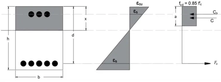
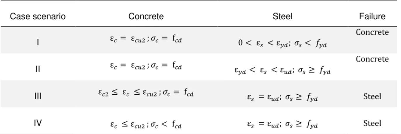
According to EC2, the verification of a singly reinforced beam involves analyzing the strain in the concrete member when it is subjected to a load. Thus, 4 scenarios can be considered to describe a state of stress-strain of a reinforced concrete member when subjected to bending moment. In Figure 2.10, and Table 2.3 the behavior of the cross section can be observed when the strains reach its limit. When the strain of the concrete or the steel reaches the ultimate strain, it is considered that the concrete member reached its limit and therefore fails.
Figure 2.10 - Stress distribution when the reinforced concrete member is subjected to bending moment [10]
Table 2.3 - Stress-strain distribution for concrete crushing and steel failure
Case scenario Concrete Steel Failure
I ε𝑐 = ε𝑐𝑢2 ; 𝜎𝑐 = f𝑐𝑑 0 < ε
𝑠 < ε𝑦𝑑; 𝜎𝑠< 𝑓𝑦𝑑
Concrete
II ε𝑐 = ε𝑐𝑢2 ; 𝜎𝑐 = f𝑐𝑑 ε
𝑦𝑑 < ε𝑠 < ε𝑢𝑑; 𝜎𝑠≥ 𝑓𝑦𝑑
Concrete
III ε𝑐2≤ ε𝑐 ≤ ε𝑐𝑢2 ; 𝜎𝑐= f𝑐𝑑 ε
𝑠 = ε𝑢𝑑; 𝜎𝑠≥ 𝑓𝑦𝑑 Steel
Figure 2.11 – Stress block considering compression reinforcement [11]
The scheme (Figure 2.11) is shown to demonstrate the case scenario for a concrete beam with compression reinforcement and how to calculate its resistance capacity. The main difference from the previous scheme, (Figure 2.10), is that, a compression force due to the compression reinforcement force is included in the equilibrium.
By knowing the initial strain, it is possible to calculate the position of the neutral axis using the same expression used in section 2.1.3 equation (1).
Considering the stress block that has been mentioned, Figure.2.8, for a given cross section, the compression force that is given by the integration of the stress-block is calculated. The stress considered has the expression (12) or (13), depending on the strain value. And the resulting compression force is given by:
𝐹𝑐 = ∫𝐴 𝜎𝑐 𝑑𝐴 (16)
The compression force is given by the sum of the two parts: the compression force after the strain reaches 𝜀𝑐𝑢2, represented by the rectangular portion of the stress-block and a second part, due to the parabolic portion, when the strain has not reach 𝜀𝑐𝑢2 yet.
Integrating the rectangular part of the stress block we get:
𝐶𝑟 = 𝑓𝑐𝑑∙ 𝜀𝑐𝑢2𝜀− 𝜀𝑐2
𝑐𝑢2 ∙ 𝑏 ∙ 𝑥 (17)
𝐶𝑝 = 𝑓𝑐𝑑∙ 𝑛 + 1 ∙𝑛 𝜀𝜀𝑐2
𝑐𝑢2 ∙ 𝑏 ∙ 𝑥 (18)
Thus, the resulting compression force is given by:
𝐹𝑐 = 𝐶𝑟+ 𝐶𝑝 (19)
The position of the compression force to the neutral axis can be calculated by solving the following integral:
𝑥 − 𝑐 =∫𝐴 𝜎𝑐∙ 𝑦 𝑑𝐴
∫𝐴 𝜎𝑐𝑑𝐴 (20)
In order to satisfy the balance of longitudinal forces we have:
∑ 𝐻 = 0 → 𝐹𝑐 = 𝐹𝑠 (21)
Where:
𝐹𝑐 is the resulting compression force;
𝐹𝑠 is the tensile force;
𝐹𝑠 = 𝜎𝑠 𝐴𝑠 (22)
and from Figure 2.9 the stress in the steel reinforcement is given by:
𝜎𝑠 = { 𝜀 𝑓𝑦𝑑 𝑓𝑜𝑟 𝜀𝑠 ≥ 𝜀𝑦𝑑
𝑠 𝐸𝑠 𝑓𝑜𝑟 𝜀𝑠< 𝜀𝑦𝑑 (23)
After calculating the compression force and the force due to the reinforcement, it is possible to calculate the resistant moment of the cross section:
𝑀𝑅𝑑= 𝐹𝑐∙ 𝑧 = 𝐹𝑠∙ 𝑧 (24)
And the nominal moment:
𝜇 = 𝑏𝑑 𝑀2𝑅𝑑𝑓
𝑐𝑑 (25)
𝑀𝐸𝑑 ≤ 𝑀𝑅𝑑 (26)
. Where:
𝑀𝐸𝑑- is the design moment
MRd- is the resistance moment
To calculate the design moment the applied load may be esteemed through one of the following four combinations according to Eurocode, depending in which environment situation the structure is. Persistent/transient design situations:
𝐸𝑑= 𝐸 ∑ 𝛾𝐺𝑗𝐺𝑗𝑘 𝑚
𝑗=1
+ 𝑃 + 𝛾𝑄𝑖𝑄𝑖𝑘+ ∑ 𝛾𝑄𝑖𝜓0𝑖𝑄𝑖𝑘 𝑛
𝑖=2
(27)
𝐸𝑑= 𝐸 ∑ 𝐺𝑗𝑘 𝑚
𝑗=1
+ 𝑃 + 𝐴𝑑+ (𝜓11𝑜𝑢 𝜓21)𝑄𝑖𝑘+ ∑ 𝜓2𝑖𝑄𝑖𝑘 𝑛
𝑖=2
(28)
Seismic design situations:
𝐸𝑑= 𝐸 ∑ 𝐺𝑗𝑘 𝑚
𝑗=1
+ 𝑃 + 𝐴𝐸𝑑+ ∑ 𝜓2𝑖𝑄𝑖𝑘 𝑛
𝑖=1
(29)
Where:
𝐸 Effect of actions;
𝐸𝑑 is the design value of effect of actions;
𝐺𝑗𝑘 is the characteristic value of permanent action j;
𝑄1𝑘 is the characteristic value of the leading variable action;
𝐴𝐸𝑘Characteristic value of seismic action;
𝐴𝐸𝑑 is the design value of an accidental action and 𝐴𝐸𝑑 = 𝛾1𝐴𝐸𝑘;
𝑃 Relevant representative value of a prestressing action;
𝛾𝐺𝑗 Partial factor for permanent action j;
𝛾1Importance factor (see EN 1998);
𝜓0 Factor for combination value of a variable action;
𝜓1Factor for frequent value of a variable action;
𝜓2Factor for quasi-permanent value of a variable action;
2.3
Comparison- ACI codes and Eurocode 2
The procedure followed in this section is for reinforced concrete members without prestress. The cross section is known and so is the bending moment. Axial forces were not considered.
To summarize the different flexural design approaches given by the European code and the American code, the following table is presented, Table 2.4:
Table 2.4 - ACI and EC2 design comparison
ACI EC2
3
Prestressed reinforced concrete members
In this chapter the different materials used for reinforced concrete members with prestress and its history will be described briefly. Also, different types of prestress systems and the flexural design method in the ultimate limit state will be presented.
In order to optimize prestressed reinforced concrete members, three types of structures were studied. conventional steel reinforced concrete structures, CFRP structures and finally mixed structures (CFRP and steel).
3.1
Prestress history
The benefits of prestressing capacities have been used from decades. The earliest date goes back to the beginning of the 18th century, a timber bridge made of timber by Stephen Harriman Long, Figure.3.1. [12].
Figure 3.1 - Prestressed wooden bridge as designed by Stephen H. Long [12]
Prestressed concrete members were well developed a few years later by Peter H. Jackson who obtained the first patent for prestressed concrete structure: a sidewalk made of prestressed cast iron and wrought iron[12].
Figure 3.2 - Prestress cast iron sidewalk as designed by Peter H. Jackson-Diagrams[12]
In the 19TH century, Eugène Freyssinet, a structural engineer who propose to replace three old suspension bridges over Allier River (France) using high quality concrete with the cost of a single one. Le Veurdre Bridge (1910), Boutiron Bridge, and Châtel-deNeuvre Bridge. However, deformation problems were detected shortly after its construction and in 1940 the bridge was destroyed during the war. In 1928 Freyssinet patent his ideas and an addendum was made. In 1930 Freyssinet demonstrates his knowledge and a few conclusions of his study are shown as an example:[12]
• the recommendation to use high-quality concrete;
• very high strength steel (wires);
• a variety of methods to tension the wires;
• the possibility of precasting several long elements on only one beam of wires followed by cutting them to the desired length;
• high strength concrete to reduce to a minimum the loss of initial prestress;
• high initial stress of tensioned steel;
An expansion of prestressed concrete occurred in Europe due to the World War I.
In 1937, the German engineer Ewald Hoyer, secured four patents about precast prestressed concrete beams.
Figure 3.3 - Prestress cast iron sidewalk as designed by Peter H. Jackson- [12]
Another contribution was made by the Belgian Gustav Magnel to solve the problem of the steel relaxation and its influence on prestressed concrete members. Corrosions are one of the main problems of steel, and in order to solve the problem of steel tendons and rebars, important research on the use of new material was and still is nowadays conducted at many European universities.
3.2
Prestress systems
Concrete members present a good behavior when subjected to compression forces, however they have a very poor behavior when subjected to tension, so the tensile strength may be neglected and therefore a solution must be provided to compensate the lack of tensile strength. Steel and FRP are materials used to compensate the lack of tension forces in the concrete beam, either as conventional reinforcement or as prestressed cables, since these materials have a high tensile strength.
Figure 3.4 – (a) Concrete member subjected to bending without prestress; (b) concrete member subjected to bending with prestress- tensile strength reduction[13]
Advantages of prestressed concrete members:
• Increased spans;
• Higher slenderness of structural elements;
• Lighter structures;
• Improved in-service and long-term behavior;
• Smaller deflections;
• Rational use of high-strength concrete and steel;
There are two ways to tension the prestress, pre-tensioning and post-tensioning. In this dissertation only the post tensioning system was evaluated comparing bonded and unbonded tendons. Figure 3.5, summarize some of the prestress existing types.
Figure 3.5 - Prestress systems
The following Figure 3.6 presents both system previously mentioned.
Figure 3.6 - Prestress systems: (a) pre-tensioning; (b) post-tensioning [14]
3.3
Bonded tendons
As shown before, the tendon used on prestressing may be bonded or unbonded. Bonded tendons have a main feature that consists in tendons forming a bond in the concrete structure by grouting over its length. The grout, most of the time is a cementitious matrix to be applied after stressing the strands. After the grout hardens the longitudinal movement is not possible, so the function of the grout is:
• Provides a continuous bond between the strand and the duct.
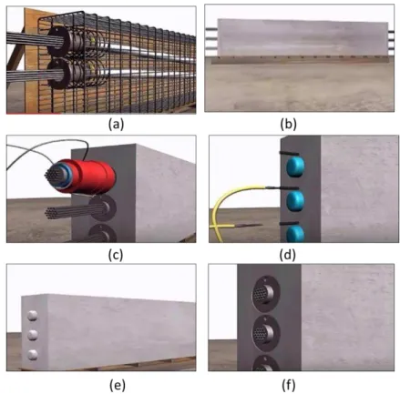
• Increase protection against corrosion, since it creates a physical barrier.
• Provides an environment non-conducted for corrosion through its alkalinity.
By compatibility, the force in the strand is directly related with the deformation of the surrounding concrete.
The losses by friction must be considered and it is higher in short tendons due to the high friction between the strand and its housing.
Figure 3.7 - Process for the manufacture of a bonded prestressed RC beam with post tension system (a) Placing prestress cables, (b) Concreting and hardening of concrete, (c) Anchoring process, (d) Grouting process, (e) Hardening of the concrete beam, (f) Anchoring detail [15]
Bonded Advantages:
• Develops higher ultimate flexural strength;
• Does not depend upon the anchorage after grouting;
• Localizes the effects of damage;
• Simple technique for demolishing or providing future opening in slab
For the design of bonded tendons, in this dissertation, the flexural design has been made according to Eurocode with the following assumptions:
• Perfect bond between tendon and concrete;
• Concrete strain capacity is assumed as 0.0035;
• Strain compatibility between prestress strain and concrete strain;
• Linear strain behavior;
• Tensile concrete strength may not be considered;
• Perfect bond between reinforcement bars and concrete;
• The deformations due to the shear forces may be neglected;
3.4
Unbonded tendons
The prestress is designated as unbonded if the tendons are not bonded to the concrete member and therefore a longitudinal displacement is allowed relatively to the concrete. The compressive force goes only and directly from the anchors to the concrete
For unbonded tendons, as shown in Figure 3.8, there is a coating material that prevents the corrosions of strands and reduces the friction effect and a plastic sheathing to encase and it acts as a bond breaker, protecting against damage by mechanical handling and barrier against intrusion of moisture and chemicals.
Figure 3.8 - Cross-section of wire unbonded tendon
When the concrete member is loaded a flexural deformation occurs and it leads to an increase in the length of the tendon. By compatibility of deformation the elongation and the strain are directly related. In that way, an increment of the stress must be considered, and it can be calculated considering the deformation and safety factors.
Unbonded Advantages:
• Provides greater available lever arm;
• Reduces friction losses;
• Simplifies pre-fabrications of tendons;
• Grouting not required;
• Can be constructed faster;
The analysis regarding unbonded tendons relies on the following assumptions:
• Tensile concrete strength may be ignored;
• A plane section remains plane after deformations;
• Perfect bond between reinforcement bars and concrete;
• The deformations due to the shear forces may be neglected;
• The stress in an unbonded tendon is constant over its full length;
• Concrete creep and tendon relaxation are not considered in the present study;
• Stress-Strain relationship is linear for both concrete and steel;
3.5
FRP
One of the major problems faced by civil engineers for construction with reinforced concrete members is the corrosion to which it is subjected, and it is directly related to their durability.
Thus, new types of materials have been studied to replace the conventional reinforcement and prestress. In this dissertation will be studied the FRP material and, more specifically the CFRP.
FRP (Fiber-reinforced polymer) are composite materials composed of aramid fibers (AFRP), basalt (BFRP), carbon (CFRP) or glass (GFRP). They can be used in aerospace, automotive, marine and construction industries, since it presents a high tensile strength.[16]
• AFRP
Aramid fibers are synthetic materials and it is known by their high strength and good heat-resistance. These fibers present a high modulus of elasticity but a low density. On the other hand, it has a higher cost than the other fibers such as glass and basalt, and therefore are less used as reinforcement in construction. In addition, the fibers of aramid also absorb moisture and must be impregnated with a polymer matrix
• BFRP
Basalt fibers are fibers with a high temperature and abrasion resistance, it has almost the same price of the glass fibers, however, the lack of guidelines for basalt by the ACI, Canadian Code and FIB makes them less competitive in the market than the other fibers.
• CFRP
• GFRP
Glass fibers have high electrical insulation properties, good heat resistance and have the lowest cost and therefore are widely used for reinforcing structures. It has a much lower modulus of elasticity than steel.
The figure below (Figure 3.9) shows the comparison between the tensile strength of different materials used in the field of civil engineering. It should be noted that carbon has a modulus of elasticity similar to that of steel.
Figure 3.9 – Tensile strength comparison for different materials [17]
.
Within all of the aforementioned fibers, the most interesting for the use of prestressing are the CFRPs because they have the highest strength and modulus of elasticity. One of the main problems with CFRP tendons is the fact that their anchoring is not a simple process for the post-tensioning or pre-tensioning systems. Each supplier produces tendons with different characteristics and for that reason to find a perfect solution is almost impossible. Another problem is the lack of lateral resistance that FRP tendons present, making it difficult to find an optimal anchoring system, because any lateral force imposed can damage the tendon, since it is a fragile material with a bad lateral resistance. Although some studies mention mechanical anchorage as a possible solution because it is easy to install [17], while some others, [18] suggest that anchorage systems of bonded type are more adequate to avoid a concentration of stress, distributing the load evenly from the anchorage to the FRP tendon.
Figure 3.10 – Bond type anchorage system [18]
3.5.1
FRP Structures
The use of FRP in civil engineering structures has been growing considerably in recent decades, especially in pedestrian bridges.
The first pre-stressed bridge built, Lunenshe Gasse Bridges, was built in 1980 Dusseldorf, Germany [20]. It is composed by twelve GFRP tendons. Figure 3.11.
Figure 3.11 - Lunenshe Gasse Bridges [20]
Figure 3.12 – (a) The Ulenbergstrasse bridges and (b) Technical data [20]
Relatively to bridges with CFRP, the first CFRP bridge with prestressed tendons was made in Japan in 1988 [21]. The first highway bridge with CFRP prestress and fibreoptic sensors was made in Alberta, Canada in 1993, the Beddington Bridges Trail, Figure 3.13.
Figure 3.13 – The Beddington Bridges Trail, Canada [21]
This bridge is composed of two spans 22.83m and 19.23m and each consisting of 13 bulb-tee sections precast and prestressed. Two types of CFRP cables were used, one produced by Tokyo Rope and the other by Mitsubishi Kasei [22].
Table 3.1 - CFRP Bridges examples
Bridge Country Year Picture
Shinmiya Bridge
First application of Carbon cable as prestressed
material
Japan 1988
Rapid City Bridge
Precast and post-tensioned bridge.
Length: 9m Span: 5.2m
United
States 1992
Tsukude Golf Country Club Bridge
Pedestrian bridge with a single span of 99.0m
Japan 1993
Beddington Trail Bridges
Highway bridge with precast and prestressed
concrete members.
Canada 1993
The West Mill Bridge
High way bridge with span of 10.0m
United
3.6
Ultimate limit state
3.6.1
Compression force
The compression force, since it only depends on the strain, is calculated the same as shown in section 2.2.4, equation (16) and (17).
3.6.2
Prestress force
The force of the prestress varies over time and it suffers instantaneous losses and long-term losses, however, it is considered a permanent action since in a short time it tends to its limit value.
According to EC2 the procedure for calculating the prestress force is given as follows:
• Maximum force 𝑃𝑚𝑎𝑥 imposed at the active end.
𝑃𝑚𝑎𝑥 = 𝐴𝑝∙ 𝜎𝑝,𝑚𝑎𝑥 (30)
Where:
𝐴𝑝 is the area of a prestressing tendon or tendons;
𝜎𝑝,𝑚𝑎𝑥 is the Maximum prestress stress;
𝜎𝑝,𝑚𝑎𝑥 = 𝑚𝑖𝑛 {𝑘1∙ 𝑓𝑝𝑘 ; 𝑘2∙ 𝑓𝑝0.1𝑘 } (31)
𝑘1 = 0.8
𝑘2= 0.9
• The value of the initial prestress force 𝑃𝑚0:
𝑃𝑚0 = 𝐴𝑝∙ 𝜎𝑝,𝑚0
where:
𝜎𝑝,𝑚0 is the stress in the tendon immediately after tensioning or transfer;
𝜎𝑝,𝑚0 = 𝑚𝑖𝑛 {𝑘1∙ 𝑓𝑝𝑘 ; 𝑘2∙ 𝑓𝑝0.1𝑘 } (32)
𝑘1 = 0.75
𝑘2= 0.85
• In the case of bonded tendons, we have:
𝐹𝑝 = 𝐴𝑝∙ 𝜎𝑝 (33)
With:
The prestress stress given by:
𝜎𝑝 = {
0.9𝑓𝑝𝑘
𝛾𝑝 𝑓𝑜𝑟 𝜀𝑝 ≥ 𝜀𝑝𝑑
𝜀𝑝 𝐸𝑝 𝑓𝑜𝑟 𝜀𝑝< 𝜀𝑝𝑑
(34)
For the case of the carbon we do not have yield plateau and thus the tension can only be calculated linearly until reaching the ultimate strain.
• In the case of unbonded tendons we have:
𝜎𝑝 ≅ 𝑃𝐴∞
𝑝 + 𝛥 𝜎𝑝,𝑈𝐿𝑆 (35)
Therefore, equation (33) into equation (30) it is possible to obtain the force of prestress that is given by:
𝐹𝑝= 𝑃∞+ 𝛥 𝜎𝑝,𝑈𝐿𝑆∙ 𝐴𝑝 (36)
Where:
𝐹𝑝 is the prestress force;
𝐴𝑝 is the area of a prestressing tendon or tendons;
𝜎𝑝 is the stress applied to the tendon;
fp is the tensile strength of prestressing;
fpk is the characteristic tensile strength of prestressing;
𝛾𝑝 is the partial factor for actions associated with prestressing;
𝑃∞ is the prestress force after all losses;
𝛥 𝜎𝑝,𝑈𝐿𝑆 is the increase of the stress from the effective prestress to the stress in the ultimate limit state
Figure 3.14 - Strain distribution for prestressed concrete beam
The prestress strain is the sum between the initial strain and the strain of tendon available in flexure. Given by:
𝜀𝑝 = ∆𝜀𝑝+ 𝜀𝑝0 (37)
The initial strain is given by the following equation:
𝜀𝑝0 =𝐴𝑃∞
𝑝∙ 𝐸𝑝 (38)
And the strain in the prestress can be obtained by geometry :
∆𝜀𝑝
𝑑 − 𝑥 = 𝜀𝑐
𝑥 (39)
The method used is the one provided by the EC, considering a parabolic-rectangular stress block and some values assumed as given values, such as: the pre-stress used, the type of concrete, the type of steel and a cross-section with a given geometry. Thus, the only unknown, is the need or not of extra reinforcement to satisfy the balance.
adjustment in the strain to reach the equilibrium is made. Once the strain is found, stress and the corresponding forces may be calculated.
3.6.3
Materials
Regarding the concrete properties used in this chapter they are the same as the ones presented in section 3.2 and for the reinforcement and prestress the following stress-strain distribution is considered. And as it can be seen, Table 3.2, steel and CFRP present different behavior that shall be considered in the design procedure. For the steel, it is possible and preferable to design after the yield point while for CFRP material this point does not exist, therefore the concrete member fails abruptly if the failure is due to CFRP reinforcement. The Table 3.2 shows these differences.
Table 3.2 - Steel and carbon. Comparison of stress-strain curves
Material Rebars Tendons
Steel
Carbon
The values of the safety factors used for each material of the prestressed reinforced concrete structure are presented in Table 3.3. For steel and concrete the values considered are given by EC2 [4] and for CFRP the safety factors considered are given by FIB [5]
𝑓𝑓𝑘
𝑓𝑓𝑑 𝑓𝑝𝑓𝑑
Table 3.3 - Material safety factors given by FIB[5] and EC2 [4]
Concrete Steel (tendons/rebars)
CFRP (Tendons)
CFRP (Rebars)
1.5 1.15 1.3 1.8
3.6.4
ULS
–
Flexural Verification
The ultimate limit state is a state in which the carrying capacity of the structure is exceeded, and therefore the safety of the structure and especially of human lives are compromised. It should be noted that the structures can be dimensioned for the ultimate limit state or for the service state, and the distinction between the two is made through the risk. Ultimate Limit State can lead to human and material losses, while the service state only leads to the discomfort of the user of the structure.
The verification of the ultimate limit state sums up the calculation of the amount of reinforcement required when the reinforced concrete member is subjected to a given moment.
For the ultimate limit state to be verified, the following condition must be satisfied:
𝐸𝑑 ≤ 𝑅𝑑
Where:
𝐸𝑑 is the value of the applied load and 𝑅𝑑 the resistant capacity;
As for the calculation of 𝑅𝑑, resistant capacity of the structure, a cross section analysis is made and as shown in Figure 3.15, these forces must be considered.
The verification of the ultimate limit state was done through the balance of the forces. Assuming an initial strain, ultimate strain and through an iterative process it was possible to find the neutral axis and the forces that balance the applied loads as well.
∑ H = 0 (40)
∑ M = 0 (41)
Where:
H are the horizontal forces;
M is the moment in the cross section;
Doing the equilibrium of the moments at the point where the reinforcement is applied, it is possible to write the following:
𝑀𝑅𝑑 = 𝐹𝑐∙ Z + 𝐹𝑝∙ 𝑧𝑝 (42)
Where:
𝑀𝑅𝑑is the resistant moment;
𝐹𝐶is the resulting compression force;
𝑍 is the level arm, the difference between the compression force and the tensile force in the reinforcement rebars;
𝐹𝑝is the force in prestressed cables;
𝑍𝑝 is the level arm, the difference between the tensile force in rebars and the prestress force;
The equilibrium given by the equation (41) the balance of the longitudinal forces is obtained.
𝐹𝑐 − 𝐹𝑝 − 𝐹𝑠 = 0 (43)
4
Parametric study for optimization of RC structures in bending
with CFRP
4.1
General considerations
CFRP are materials with high performance fibers that have been used in civil construction in order to replace the conventional steel used as reinforcement and pre-stress. The lack of uniformity in the guidelines and the high cost are some of the characteristics that prevent this material from expanding exponentially in its use for the structures. The feasibility of the solution is directly related to the amount of material used, which may vary depending on the type of reinforcement, the design procedure and the value of the safety factor.
Several recommendations [5], [7], [23], [24] for CFRP structures exist today, but they do not agree with the value of the safety factor or with the design procedure itself.
Thus, a parametric study has been conducted and it is presented in this paper to show the impact on design results caused by using different design concepts, for the possible failure modes, for the type of material used as reinforcement and tendons and for the type of prestress system (bonded or unbonded). Prestressed and non-prestressed sections are analyzed in the following chapter.
The main goal of this dissertation is to analyze and optimize the design procedure for CFRP reinforced concrete structures.
4.2
The code developed
In order to help on solving the problems that have been mentioned, a study that used Visual Basic Application (VBA) was developed and in this way several other programs were created.
Thus, the results obtained by the program were based on the balance of forces and therefore for a cross-section, with a given geometry and known mechanical properties, it was possible to calculate the amount of reinforcement required that satisfies the equilibrium condition.
The codes are subdivided into 4 subparts: Input, Constitutive Laws, Calculation process and Output. And to demonstrate what was developed in a brief way it is presented a flowchart in Figure 4.1 to summarize the codes presented in the appendices.
Input- In this section all variables are entered manually. Program users have the freedom to choose the type of concrete and steel they want to work with, as well as the cross-section geometry and the limit strains of each material in a database table. Each code has its own table and properties to vary. Regarding the CFRP material the user must decide the specified values, which means, the safety factor is applied after, during the iteration process.
Constitutive Laws- In this section is defined the type of stress-strain diagram used to calculate the
stress at the point of interest.
Calculation process- The part of the calculation itself, where the loop is drawn and by an iterative
process seeks the balanced solution. The process in program 1 and 2 generates values for µ from 0 to 0.48 with the increment of 0.01 and µ is directly proportional to the applied moment. Regarding the program for prestressed members, the value of the input becomes the applied moment and in a second case the width of the cross section. And finally, the last one, varying the value of the initial force of the prestress.
With the limit strain defined as input it is possible to calculate the neutral axis and consequently the stress. After determining tensions, it is possible to calculate the resulting compression force and the tensile force applied to the reinforcement. Once these forces have been calculated, we only have to calculate the moment at one of these points and we can obtain the resistant moment of the cross section. This moment is compared later with the applied moment and if the difference between them is less than 10-5 we consider that the moments are equal and as such, we find the solution and the loop ends. If the applied moment is smaller than the resistant one we have to follow the strain curve of the concrete and we divide the strain value by half in each iteration, reducing the compressed zone until the equilibrium is found. If the applied moment is greater than the resistant one, we elaborate the same procedure but following the steel strain way.
Output –The output of the program consists of many different variables and we can chose among those
4.2.1
Properties of materials
The properties of the CFRP tendons used in the code are shown in Table 4.1
Table 4.1 – Properties of CFRP tendons CFRP Tendons
𝒇
𝐩𝐤(MPa) 2690𝒇
𝐩𝟎,𝟏𝐤(MPa) 2421𝒇
𝐩𝐝(MPa) 2022.56𝐄
𝐟 (GPa) 155𝜺
𝐮𝐤(‰)
17,35𝜸
𝐟 1.33𝐀
𝐩 (cm2) 11.0544𝐏
𝐦𝟎(kN)
1275,46𝚫𝐏
𝐜+𝐬+𝐫(%)
10On the other hand, the type of tendon selected is steel, the data considered are as follows in Table 4.2.
Table 4.2 – Properties of steel tendons Steel Tendons
𝒇
𝐩𝐤(MPa) 1770𝒇
𝐩𝟎,𝟏𝐤(MPa) 1593𝒇
𝐩𝐝(MPa) 1539,13𝐄
𝐬 (GPa) 195𝜺
𝒖𝒌(‰)
25𝜸
𝒔 1.15𝐀
𝐩 (cm2) 11.0544𝚫𝐏
𝐜+𝐬+𝐫(%)
10
For the type of ordinary reinforcement, it is possible for the user to choose CFRP or steel and the characteristics of the rebar of each material are in Tables 4.3 and Table 4.4 respectively.
Table 4.3 - Properties of CFRP rebars Carbon_Rebars
𝒇
𝐟𝐤 (MPa) 2550.0𝒇
𝐟𝐝 (MPa) 1416,67𝐄
𝐟 (GPa) 158,0𝜺
𝐟𝐤(‰)
16,14𝜺
𝐟𝐝(‰)
8,97𝜸
𝐟 1.8
Table 4.4 - Properties of CFRP rebars Steel_rebars
𝒇
𝐲𝐤 (MPa) 500𝒇
𝐲𝐝 (MPa) 434,78𝐄
𝐬 (GPa) 200𝜺
𝐮𝐤(‰)
25𝜺
𝐲𝐝(‰)
2.174𝜸
𝒔 1.15Where:
A
pis the area of a prestressing tendon or tendons;
E
fis the elastic modulus of FRP;
E
sis the elastic modulus of steel;
𝑓
fkis the characteristic value of tensile strength of FRP reinforcement and
𝜀
fkis its respective strain;
𝑓
ydis the design yield strength of reinforcement and
𝜀
ydis its respective strain;
𝑓
ykis the characteristic yield strength of reinforcement;
𝜀
ukis the characteristic strain of reinforcement or prestressing steel at maximum load;
Δ
P
c+s+r(%)
Are the long-term losses due to creep, shrinkage and relaxation at location x, at time t;𝛾
fpartial safety factor for FRP;
𝛾
𝑠partial safety factor for Steel;
Since, as previously mentioned, there is no European standard for the design of FRP structures, the values of these safety factors (Table 4.1-Table 4.4) were taken from previous studies [25] and guideline [5].
Case 1
In the case 1 the parameters of the cross-section as well as the properties of the concrete to be used are always constant and considered as input for the program. Table 4.5 and Table 4.6.
Table 4.5 – Geometry of the cross section for case 1 Cross_Section
h(m) 1.1 dp(m) 1.075
d(m) 1.153 b(m) 0.96 e(m) 0.49
Table 4.6 – Concrete properties for case 1 Concrete
𝒇
𝐜𝐤 (MPa) 30𝒇
𝒄𝒅 (MPa) 17εc2(‰) 2
εcu2(‰) 3.5
![Figure 2.2 – Parabolic-rectangular stress-strain curve for concrete adapted from ACI [6]](https://thumb-eu.123doks.com/thumbv2/123dok_br/16622143.740227/27.892.96.791.104.902/figure-parabolic-rectangular-stress-strain-curve-concrete-adapted.webp)
![Figure 2.8 - Parabola-rectangle, bilinear and rectangular stress block adapted from Eurocode 2 [4]](https://thumb-eu.123doks.com/thumbv2/123dok_br/16622143.740227/36.892.108.864.204.391/figure-parabola-rectangle-bilinear-rectangular-stress-adapted-eurocode.webp)
![Figure 2.11 – Stress block considering compression reinforcement [11]](https://thumb-eu.123doks.com/thumbv2/123dok_br/16622143.740227/38.892.207.679.125.448/figure-stress-block-considering-compression-reinforcement.webp)
![Figure 3.2 - Prestress cast iron sidewalk as designed by Peter H. Jackson-Diagrams[12]](https://thumb-eu.123doks.com/thumbv2/123dok_br/16622143.740227/44.892.276.616.127.463/figure-prestress-cast-sidewalk-designed-peter-jackson-diagrams.webp)
![Figure 3.3 - Prestress cast iron sidewalk as designed by Peter H. Jackson- [12]](https://thumb-eu.123doks.com/thumbv2/123dok_br/16622143.740227/45.892.270.624.128.389/figure-prestress-cast-iron-sidewalk-designed-peter-jackson.webp)
![Figure 3.11 - Lunenshe Gasse Bridges [20]](https://thumb-eu.123doks.com/thumbv2/123dok_br/16622143.740227/52.892.264.625.664.1021/figure-lunenshe-gasse-bridges.webp)

