Rev Odontol UNESP. 2018 July-Aug.; 47(4): 237-243 © 2018 - ISSN 1807-2577
ORIGINAL ARTICLE
Doi: https://doi.org/10.1590/1807-2577.05418
This is an Open Access article distributed under the terms of the Creative Commons Attribution License, which permits unrestricted use, distribution, and reproduction in any medium, provided the original work is properly cited.
Biomechanical effect of inclined implants in fixed prosthesis:
strain and stress analysis
Efeito biomecânico de implantes inclinados em prótese fixa: analise das tensões e deformações
Vinícius Anéas RODRIGUES
a, João Paulo Mendes TRIBST
b*, Leandro Ruivo SANTIS
b,
Alexandre Luiz Souto BORGES
b, Renato Sussumu NISHIOKA
baFaculdade de Pindamonhangaba, Pindamonhangaba, SP, Brasil
bUNESP – Universidade Estadual Paulista, Instituto de Ciência e Tecnologia, Departamento de Materiais
Odontológicos e Prótese, São José dos Campos, SP, Brasil
Resumo
Introdução: A inclinação dos implantes pode ser corrigida através de mini-pilares de diferentes angulações.
Objetivo: Analisar a influência de implantes com hexágono externo em diferentes inclinações (3 níveis) na distribuição de microdeformações geradas em torno de três implantes. Método: Um modelo geométrico de osso foi criado através do software CAD Rhinoceros (versão 5.0 SR8, Mcneel North America, Seattle, WA, EUA). Três implantes (4,1 × 13 mm) foram modelados e inseridos no interior do substrato em três diferentes inclinações: 0º, 17º e 30º. Em seguida, todos os grupos receberam mini-pilares cônicos, parafusos de fixação e prótese simplificada. A geometria final foi exportada em formato STEP para software de análise e todos os materiais foram considerados homogêneos, isotrópicos e linearmente elásticos. Uma carga axial (300N) foi aplicada no centro da prótese. Um estudo in vitro foi conduzido com as mesmas condições e grupos para validar o modelo tridimensional. Resultado: A concentração de tensão ocorreu na área externa dos implantes, em contato com o osso cortical e o hexágono externo. Para o simulador ósseo, a deformação aumentou na região peri-implantar de acordo com o aumento da inclinação do implante. A diferença entre os grupos foi significativa (p = 0.000). O grupo de 30º apresentou maior concentração de tensão e deformação. Conclusão: O aumento da microdeformação e das tensões ao redor dos implantes aumenta diretamente proporcional ao aumento do ângulo de instalação.
Descritores: Análises de elementos finitos; implante dentário; prótese fixa.
Abstract
Introduction: Implant inclinations can be corrected using mini abutments at different angulations. Objective: To analyze the influence of external hexagon implants in different inclinations (3 levels) on the microstrain distribution generated around three implants. Method: A geometric bone model was created through Rhinoceros CAD software (version 5.0 SR8, Mcneel North America, Seattle, WA, USA). Three implants (4.1 × 13 mm) were modeled and inserted inside the substrate at three different inclinations: 0º, 17º and 30º. Next, all groups received mini conical abutments, fixation screws and a simplified prosthesis. The final geometry was exported in STEP format to analysis software and all materials were considered homogeneous, isotropic and linearly elastic. An axial load (300N) was applied on the center of the prosthesis. An in vitro study was conducted with same conditions and groups for validating the tridimentional model. Result: Stress was concentrated on the external area of the implants, in contact with the cortical bone and external hexagon. For the bone simulator, the strain increased in the peri-implant region according to the increase in the implant’s inclination. The difference between groups was significant (p = 0.000). The 30º group presented higher stress and strain concentration. Conclusion: The microstrain and stress increase around implants directly proportional to the increase of the installation angle.
Descriptors: Finite element analyses; dental implant; fixed prosthesis.
INTRODUCTION
In clinical situations where dental implants are inclined inside bone tissue, the use of angulation-correcting abutments may be an alternative for prosthesis installation1-3. Although the use
of these abutments solves part of the prosthetic complications,
masticatory load dissipation will be modified when this set enters into function4.
of the implant in position5,6. Despite the possibility of reducing the
treatment longevity due to implant’s inclination the clinician will need this arrangement several times due to anatomical accidents and bone disposition which restricts installation sites7. The decision
to install an inclined implant can be scientifically based on several articles that evaluated inclined implants in anterior regions, with reduced occlusal load and contact on the prosthetic crown’s palatine face8-10. These studies mostly express a common clinical situation
and provide the dentist with an initial basis that inclined implants aggravate the strain generated around the supporting tissue, but the physiological limit is still maintained9. However, there are
components in various angles without manufacturer restrictions on the regions in which they can be used. Also, there are no reports in the literature of more extensive situations in which all implants were angled and their angulation was corrected by these prosthetic pieces.
In order to analyze the stress generated around the implants, the correlation of two or more methodologies can reduce erroneous inferences, and thus increase the clinical validity of the study11,12.
Finite element analysis (FEA) is widely used as a methodology to study dental implants and allows for tridimensional simulation of occlusal loads in the implant structure13,14. Associated with FEA,
Strain Gauge (SG) can validate the tridimensional model in vitro, and thus certify that the responses generated by the software have real behavior.
The purpose of this study was to analyze the influence of mini abutments at different inclinations (3 levels: 0º, 17º and 30º) on the microstrain distribution generated around three external hexagon implants. The null hypothesis was that abutment’s angulation does not interfere in the mechanical behavior of implants or peri-implant tissue.
METHOD
Three-Dimensional Models
Pre-processing
A tridimensional (3D) rectangular model (95 × 16 × 20 mm) was created from Rhinoceros CAD software (version 5.0 SR8, McNeel North America, Seattle, WA, USA) to simulate geometric bone tissue14. Then, three implants were modeled following the
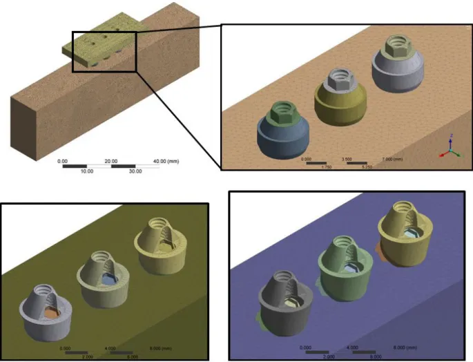
manufacturer’s dimensions (4.1 × 13 mm) containing an external hexagon of 0.7 mm. Implants were arranged in a linear way with 3.0 mm between them. The implants were replicated and new groups were created with inclinations of 17º and 30º. Mini-abutments with a height of 3.5 mm were modeled for each implant in all groups with a fixation screw and a prosthetic screw. For groups with inclined implants, the abutments were modeled with an angled platform to correct the prosthetic insertion trajectory (Figure 1). The three groups were inserted into identical bone tissue simulator blocks and received a fixed prosthesis.
The bodies were imported in STEP format into Ansys software (ANSYS 17.2, ANSYS Inc., Houston, TX, USA) and mechanical properties of each were reported based on the literature15-17, following
a previously published methods12,14. The Meshes were created based
on convergence test (10%) and the size of 0.3 mm was selected for each element14. 754,936 nodes with 440,893 elements were
created for the block with perpendicular implants, 732,375 nodes with 428,219 elements for the block with the inclined implant at 17°, and 733,412 nodes with 430,217 elements for the block with the inclined implant at 30°.
FEA loading and fixation
The fixation was located on the external lower surface of the model. The loading point (2 mm, diameter) was located at the center of the fixed prosthesis. Load was defined as the vector in the Z axis with 300 N in an apical direction. The required solutions were: Von Mises stress for implants and elastic strain for peri-implant tissue. Results were placed on an identical values scale to allow visual comparison through color charts.
Validation of 3D Model
Samples confection
Three polyurethane (Polyurethane F16 Axson, Cercy - France) blocks were created with exact measurements of the initial 3D model (95 × 45 × 40 mm) using a metal die. The blocks’ surfaces were
regularized with granulated sandpapers of #220 to #600 (3M ESPE, St. Paul, USA), and then three implants were installed in each block following a conventional drilling protocol (AS TECHNOLOGY TITANIUM FIX, São José dos Campos, Brazil). Metallic devices were used to standardize the perforations according to the “inclination” factor of the study (0º, 17º and 30º). Mini conical abutments (AS TECHNOLOGY TITANIUM FIX, São José dos Campos, Brazil) were positioned on each implant platform. The prosthetic abutments were installed with a torque of 20 Ncm with the aid of a manual torquemeter. Simplified fixed prostheses (N=30, n=10) were melted in nickel-chromium (Wironia Light Bego, Bremen, Germany) following the same dimensions of the 3D model.
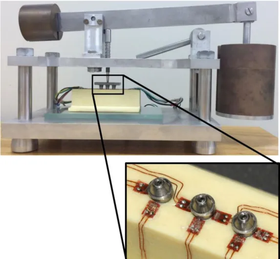
Block surfaces were cleaned with isopropyl alcohol and seven linear strain gauges (Model KFG-02-120-C1-11, Kyowa Eletronic Instruments Co., Ltd-Tokyo-Japan) were attached to each block with cyanoacrylate adhesive (Super Bonder Loctite, São Paulo, Brazil) in 7 different areas (Figure 2). Next, the calibration of each extensometer was performed using a multimeter device (Minida ET 2055: Minida São Paulo - Brazil). Variations of electrical resistance were converted to microstrain units through an electrical signal conditioning apparatus (Model 5100B Scanner - System 5000 - Instruments Division Measurements Group, Inc. Raleigh, North Carolina - USA). Data recording was performed using Strain-smart software.
Load aplication
Constant static loading (30 kgf, 10 s) was promoted by a device with a 2 mm rounded tip (Figure 2) which allowed three loading repetitions on the center of the prostheses (n = 10)12.
Data analysis
Qualitative stress results obtained by the computational mathematical model were analyzed according to colored scales. The strain results are presented in graphs. Descriptive statistics consisted of means and standard deviations, and inferential statistical analysis consisted of a 95% confidence interval one way ANOVA analysis using MINITAB software (Minitab, version 16.1.0, 2012).
RESULT
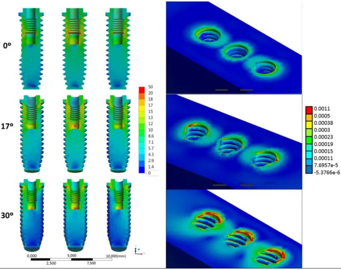
After computational simulation, the MPa results of stress generated on each implant’s were photographed with the same representative color scale. The hottest points represent areas with the highest concentration of positive values (traction), while the cooler zones represent zones with smaller values (compression). In this regard, the increase in stress concentration was proportional to the increase of the implants’ inclination (Figure 3). Maximum strain found on the bone’s surfaces and peri-implant tissue exhibited similar behavior to implants (Figure 3). Values of strain were
compared with SG results (Table 1). Statistical analysis showed that the “inclination” factor was significant (p = 0.000) for the in vitro results; and the mechanical behavior of the 3D model is assumed valid, as both methodologies corroborated the results.
DISCUSSION
According to the results obtained in the present study, it was observed that the hypothesis was rejected because the implants’ and the bone tissue’s mechanical behavior were altered due to the implants’ inclination.
In comparing both used methodologies, it is possible to observe that FEA shows values with more than 10% difference
Table 1. Mean of normal strain (dimensionless) measured by both methods
Computational Experimental
0° 540 567(± 120)A
17° 1100 1288 (± 387)B
30° 1550 1725 (± 417)C
Legend: Different capital letters indicate statistically significant differences ( Tukey’s test α = 5%).
between groups, which exceeds the convergence test value of the mesh generation, and can be understood as significantly different (Table 1). In the same way, SG verified statistical difference between microstrain values found around straight compared to inclined implants (p=0.000). Thus, both methodologies indicate that the greater the inclination of the implants, the greater the generated bone deformation (Figure 3), which is according to the study of Clelland et al.18 (1996). These regions where higher microstrain
concentrations occurred are more susceptible to bone crest micro fractures around the implant4. When strain values exceed
physiological bone tolerance, they cause irreversible damage at the bone-implant interface19, and thus initiate a process of unwanted
bone remodeling since it culminates in insertion loss5.
The results of this present study did not show values above the physiological limit (Figure 3) as demonstrated by situations with prosthesis with a less number of elements20. Thus, although other
factors may modify the peri-implant region21, the stresses generated
appear to be acceptable and the use of these components can be performed without initial problems. Considering that the study used a four-element prosthesis, it is believed that the center point is the region that would allow a better load distribution between implants, and this would explain the symmetry of the stress generated between the lateral implants, but the strain’s physiological limit was achieved even in this situation. For the stress generated in implants, no values of critical tensile stress of titanium12 were
recorded (Figure 3). However, it is believed that in long term, the group with 30º angled implants would present possible failures due to fatigue since the stress accumulated in the metallic structures was larger with the same applied load.
The load used was 30.6 kgf. (300 N), being a mean load obtained in the first molar region22. The study did not consider the
bone variations existing in vivo conditions due to the difficulty of standardization and reproducibility between two methodologies. Thus, polyurethane (an isotropic material previously validated in the literature) was used as a replacement of bone tissue for laboratory analysis17.
The fixed prosthesis model was chosen considering that this configuration favors the load distribution on implants when compared with different configurations23. Other studies have been
carried out with this prosthesis configuration in order to observe
the behavior of microstrains around implants14,24, but an evaluation
of the biomechanical behavior of inclined implants has not been discussed in the literature.
The implants were installed linearly with angles of 0°, 17° and 30°, as previous studies showed that there was no statistical difference when compared to implants in a linear position or offset24.
The prosthetic screw is one of the main regions of stress concentration and possible mechanical failure in the implant/prosthesis25,26. Thus,
the concentration of stresses can be facilitated during incidence of oblique loads6,21,24. As the present study used a simplified fixed
prosthesis, the generated stress inferences in the abutment and screw would not correspond to reality, as verified during the 3D model validation14. Nevertheless, the literature is rather concise
in emphasizing possible damage on the prosthetic screw when used in inclined implants6,8,14,21. Future studies evaluating fatigue
life and torque maintenance of prosthetic screws in straight and angled abutments should be performed to complement the available literature data.
The von-Mises stress is directly related to the ductile metals failure25-28. Therefore, restorative procedures that involve stress maps
with greater magnitude show higher possibility of premature failure6.
Considering the dental implants, studies that have evaluated this type of failure criteria during computational simulations are quite common in order to prevent critical damages in implant-supported prosthesis24-28.
The use of abutments to correct implant position in fixed prostheses can provide a correct insertion trajectory facilitating the implant-supported prosthesis installation6,21. But, at the same time
those abutments can make the biomechanics response more fragile due to the increase of stresses concentration in the implants and bone strain. Moreover, according to the figure 3, as the angulation increases the zones of stress concentration prevail in the implant cervical region, especially below the prosthetic platform before the first thread.
CONCLUSION
Within this study’s limitations, it may be concluded that the microstrain and stress increase around implants directly proportional to the increase of the installation angle.
REFERENCES
1. Saab XE, Griggs JA, Powers JM, Engelmeier RL. Effect of abutment angulation on the strain on the bone around an implant in the anterior maxilla: a finite element study. J Prosthet Dent. 2007 Feb;97(2):85-92. http://dx.doi.org/10.1016/j.prosdent.2006.12.002. PMid:17341376. 2. Akkad S, Richards M. Solutions for severely angulated implants in the mandibular overdenture: a clinical report. J Prosthodont. 2009
Jun;18(4):342-7. http://dx.doi.org/10.1111/j.1532-849X.2008.00400.x. PMid:19054301.
3. Stephens GJ, di Vitale N, O’Sullivan E, McDonald A. The influence of interimplant divergence on the retention characteristics of locator attachments, a laboratory study. J Prosthodont. 2014 Aug;23(6):467-75. http://dx.doi.org/10.1111/jopr.12144. PMid:24750293.
4. Watanabe F, Hata Y, Komatsu S, Ramos TC, Fukuda H. Finite element analysis of the influence of implant inclination, loading position, and load direction on stress distribution. Odontology. 2003 Sep;91(1):31-6. http://dx.doi.org/10.1007/s10266-003-0029-7. PMid:14505187.
5. Frost HM. Wolff ’s law and bone’structural adaptations to mechanical usage: an overview for clinicians. Angle Orthod. 1994;64(3):175-88. PMid:8060014.
7. Krekmanov L. Placement of posterior mandibular and maxillary implants in patients with severe bone deficiency: a clinical report of procedure. Int J Oral Maxillofac Implants. 2000 Sep-Oct;15(5):722-30. PMid:11055139.
8. Wang C, Zhang W, Ajmera DH, Zhang Y, Fan Y, Ji P. Simulated bone remodeling around tilted dental implants in the anterior maxilla. Biomech Model Mechanobiol. 2016 Jun;15(3):701-12. http://dx.doi.org/10.1007/s10237-015-0718-5. PMid:26285769.
9. Zhang G, Yuan H, Chen X, Wang W, Chen J, Liang J, et al. A tridimensional finite element study on the biomechanical simulation of various structured dental implants and their surrounding bone tissues. Int J Dent. 2016;2016:4867402. http://dx.doi.org/10.1155/2016/4867402. PMid:26904121.
10. Álvarez-Arenal Á, Segura-Mori L, Gonzalez-Gonzalez I, DeLlanos-Lanchares H, Sanchez-Lasheras F, Ellacuria-Echevarria J. Stress distribution in the transitional peri-implant bone in a single implant-supported prosthesis with platform-switching under different angulated loads. Odontology. 2017 Jan;105(1):68-75. http://dx.doi.org/10.1007/s10266-016-0237-6. PMid:26943357.
11. Pesqueira AA, Goiato MC, Gennari H Fo, Monteiro DR, Santos DM, Haddad MF, et al. Use of stress analysis methods to evaluate the biomechanics of oral rehabilitation with implants. J Oral Implantol. 2014 Apr;40(2):217-28. http://dx.doi.org/10.1563/AAID-JOI-D-11-00066. PMid:24779954.
12. Tribst JPM, Dal Piva AMO, Borges ALS. Biomechanical tools to study dental implants: a literature review. Braz Dent Sci. 2016;19(4):5-11. http://dx.doi.org/10.14295/bds.2016.v19i4.1321.
13. Lanza MDS, Seraidarian PI, Jansen WC, Lanza MD. Stress analysis of a fixed implant-supported denture by the finite element method (FEM) when varying the number of teeth used as abutments. J Appl Oral Sci. 2011 Dec;19(6):655-61. http://dx.doi.org/10.1590/S1678-77572011000600019. PMid:22231003.
14. Tribst JPM, Rodrigues VA, Borges ALS, Lima DR, Nishioka RS. Validation of a simplified implant-retained cantilever fixed prosthesis. Implant Dent. 2018 Feb;27(1):49-55. PMid:29341975.
15. Benzing UR, Gall H, Weber H. Biomechanical aspects of two different implant-prosthetic concepts for edentulous maxillae. Int J Oral Maxillofac Implants. 1995 Mar-Apr;10(2):188-98. PMid:7744438.
16. Stegaroiu R, Sato T, Kusakari H, Miyakawa O. Influence of restoration type on stress distribution in bone around implants: a tridimensional finite element analysis. Int J Oral Maxillofac Implants. 1998 Jan-Feb;13(1):82-90. PMid:9509784.
17. Miyashiro M, Suedam V, Moretti RT No, Ferreira PM, Rubo JH. Validation of an experimental polyurethane model for biomechanical studies on implant supported prosthesis – tension tests. J Appl Oral Sci. 2011 Jun;19(3):244-8. http://dx.doi.org/10.1590/S1678-77572011000300012. PMid:21625741.
18. Clelland NL, Carr AB, Gilat A. Comparison of strains transferred to a bone simulant between as-cast and postsoldered implant frameworks for a five-implant-supported fixed prosthesis. J Prosthodont. 1996 Sep;5(3):193-200. http://dx.doi.org/10.1111/j.1532-849X.1996.tb00296.x. PMid:9028224.
19. Rangert BR, Sullivan RM, Jemt TM. Load factor control for implants in the posterior partially edentulous segment. Int J Oral Maxillofac Implants. 1997 May-Jun;12(3):360-70. PMid:9197101.
20. Wiskott HW, Belser UC. Lack of integration of smooth titanium surfaces: a working hypothesis based on strains generated in the surrounding bone. Clin Oral Implants Res. 1999 Dec;10(6):429-44. http://dx.doi.org/10.1034/j.1600-0501.1999.100601.x. PMid:10740452.
21. Rodrigues VA, Tribst JPM, Santis LR, Lima DR, Nishioka RS. Influence of angulation and vertical misfit in the evaluation of microdeformations around implants. Braz Dent Sci. 2017 Jan-Mar;20(1):32-9. http://dx.doi.org/10.14295/bds.2017.v20i1.1311.
22. Mericske-Stern R, Assal P, Mericske E, Bürgin W. Oclusal force and oral tactile sensibility measured in partially edentulous patients with ITI implants. Int J Oral Maxillofac Implants. 1995 May-Jun;10(3):345-53. PMid:7615331.
23. Rangert B, Krogh PH, Langer B, Van Roekel N. Bending overload and implant fracture: a retrospective clinical analysis. Int J Oral Maxillofac Implants. 1995 May-Jun;10(3):326-34. PMid:7615329.
24. Vasconcellos LG, Nishioka RS, Vasconcellos LM, Balducci I, Kojima AN. Microstrain around dental implants supporting fixed partial prostheses under axial and nonaxial loading conditions, in vitro strain gauge analysis. J Craniofac Surg. 2013 Nov;24(6):e546-51. http:// dx.doi.org/10.1097/SCS.0b013e31829ac83d. PMid:24220463.
25. Tribst JPM, Morais DC, Alonso AA, Piva AMOD, Borges ALS. Comparative three-dimensional finite element analysis of implant-supported fixed complete arch mandibular prostheses in two materials. J Indian Prosthodont Soc. 2017 Jul-Sep;17(3):255-60. http://dx.doi.org/10.4103/ jips.jips_11_17. PMid:28936039.
26. Tribst JPM, Dal Piva AMO, Shibli JA, Borges ALS, Tango RN. Influence of implantoplasty on stress distribution of exposed implants at different bone insertion levels. Braz Oral Res. 2017 Dec;31(0):e96. http://dx.doi.org/10.1590/1807-3107bor-2017.vol31.0096. PMid:29236900. 27. Tribst JPM, Dal Piva AMO, Rodrigues VA, Borges ALS, Nishioka RS. Stress and strain distributions on short implants with two different
prosthetic connections–an in vitro and in silico analysis. Braz Dent Sci. 2017 Jul-Sep;20(3):101-9. http://dx.doi.org/10.14295/bds.2017. v20i3.1433.
28. Tribst JPM, Piva AMODAL, Borges ALS, Bottino MA. Influence of crown and hybrid abutment ceramic materials on the stress distribution of implant-supported prosthesis. Rev Odontol UNESP. 2018;47(3):149-54. http://dx.doi.org/10.1590/1807-2577.04218.
CONFLICTS OF INTERESTS
*CORRESPONDING AUTHOR
João Paulo Mendes Tribst, UNESP – Universidade Estadual Paulista, Instituto de Ciência e Tecnologia, Departamento de Materiais Odontológicos e Prótese, Av. Eng. Francisco José Longo, 777, 12245-000 São José dos Campos - SP, Brasil, e-mail: joao.tribst@ gmail.com