Stress Analysis of Steam Generator Shell
Nozzle Junction for Sodium cooled Fast
Breeder Reactor
Mani N1 Thanigaiyarasu G2 Chellapandi P3
1
Research Scholar, Anna University
2
Professor, Anna University, Chennai
3
Associate Director, Reactor Engineering Group, IGCAR, Kalpakkam, India ABSTRACT
The Steam Generators (SG) decides the capacity factor in Sodium cooled Fast breeder Reactor (SFR) plants and hence they are designed with high reliability. One of the critical locations in SG is the shell nozzle junction. This junction is subjected to an end bending moment and internal pressure. Since the shell nozzle junction is the critical location of SG a double-ended guillotine rupture will result in leakage of large quantity of sodium, which is not desirable. The material of construction is modified 9Cr-1Mo. Hence safety requirements demand that Leak Before Break criteria with assumed initial flaw have to be demonstrated. To demonstrate LBB, the basic requirement is to predict the state of stress precisely in the shell nozzle junction under various loading conditions. An efficient finite element modeling for shell nozzle junction has been presented in which shell elements are employed to idealize the whole region. These results are used for the analysis of leak before break concept.
Keywords: SFR, SG, modified 9Cr-1Mo Steel, Shell Nozzle Junction, LBB 1. Introduction
The structural reliability of Sodium cooled Fast Reactor (SFR) components is ensured by the choice of high ductile materials, design and construction as per international codes, such as, CEGB-R6 [1986], RCC-MR [2002], ASME-Sec III, Division.1 [2001] and ASME, Sec-XI [1989]. In order to respect the design code rules, detailed analyses in various domains are performed using thoroughly validated computer codes. In 500 MWe Sodium cooled Fast Reactor, the critical out-of-core components are main vessel, control plug, inner vessel, intermediate heat exchanges, Steam Generators (SG) and hot pipelines. Figure 1 shows the flow sheet of SFR which indicates the critical components. Austenitic stainless steel type 316 LN is the main structural material for the out-of-core components and modified 9Cr-1Mo is chosen for steam generator.
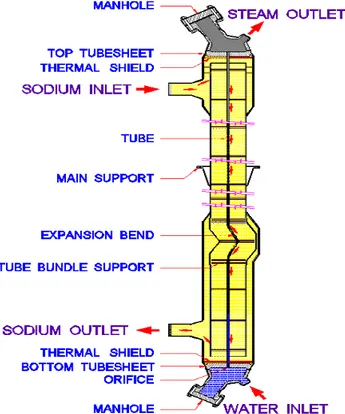
Steam generator is an important component of Nuclear Reactor. Operating experience on steam generator has shown that this component plays an important role in influencing the plant capacity factor. The geometry of SG is a tall vertical once through shell and tube type exchanger supported at the middle. In SFR, there are 8 steam generators, 4 in each of the two secondary loops. SG is once through integrated. Figure 2 shows SG configuration. The geometry of SG consists of two thick tube sheets connected by tubes and outer shell with bends near the bottom tube sheet. Sodium enters through a single inlet nozzle, flows upwards in the annular region and then flows down through the top inlet plenum where it is evenly distributed before entering the tube bundle. After flowing downwards on the outside of the tubes, sodium exits through the single outlet nozzle via the bottom outlet plenum. Feed water enters the tube side at the bottom, flows through the orifice incorporated for creating the desired pressure drop from SG stability consideration and flows upward in a counter flow direction to the down coming sodium.
between the two materials is high, there is a tri metallic joint (Gr91+Alloy 800+ 316LNSS) between the piping and nozzle as shown in figure 3
2. Objective
The objective of this paper is, to evaluate the realistic state of stress in the junction so as to identify the critical location in the nozzle where notch is to be made for further analysis of leak before break.
Figure 2 Schematic sketch of SFR-SG.
3. Stress Analysis of SG Shell nozzle junction
3.1 Introduction
In the present project scaled down model of actual Shell Nozzle Junction (SNJ) is modeled and analyzed using ANSYS 10. Generally the pipe which carries sodium from surge tank to the SG nozzle causes bending moment on the shell nozzle junction. Stresses in the shell nozzle junction are analyzed to assess its structural integrity for the external bending moment which is caused due to vertical load at the end of the nozzle.
3.2 Definition of the problem
An external bending moment caused due sodium piping at the hot end nozzle (798k) of SG is considered for the analysis. The bending moment causes stresses in the nozzle, as well as in the shell. So stress analysis of the shell-nozzle junction is performed to check the structural integrity
3.3 Geometrical details of SNJ
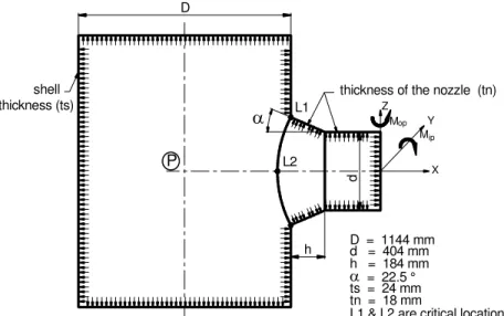
Static FE analysis is carried out using ANSYS on half symmetric scaled down model of the shell nozzle junction. The internal diameter of the main tube is 1177 mm and that of the nozzle is 386 mm. The thickness of the main tube is 24 mm while that of the nozzle is 18 mm. The cylindrical shell has a pullout at 90o to its axis. This pullout will be welded to a conical reducer whose small end is attached to the connected piping. In order to reduce stress concentration, welding is avoided at the junction of cylindrical shell and the nozzle and the junction is made by pulling a portion of the shell in hydraulic press.
Table 1 Load Case Table 2 Material Properties
3.4 Boundary Conditions and Loading
The flange plates at the top and bottom of the cylindrical shell are fixed. In the case of half symmetric models, appropriate boundary conditions were assumed to represent geometric and loading symmetries. Concentrated loads are applied at the end of the nozzle so as to develop the equivalent end moment. Pressure load is applied throughout the inner surface of the model, which includes the shell, the nozzle and the end plates. Three load cases were considered for an analysis of all the models. These are given in table 1. Figure 4 shows the boundary condition & loading details of shell nozzle junction. The material properties taken for this analysis are given in table 2.
3.5 Modelling and Description of the analysis model
Scaled down model of the actual shell nozzle junction is created using ANSYS. First half shell model is created for analysis by taking advantage of symmetry. In the next step nozzle is created. The nozzles are assumed to be welded to the cylindrical shells with full penetration welds; however any effects of corner fillet welds are disregarded in the analysis. The element chosen for this analysis is SHELL 93. The size of the elements in the vicinity of the shell/nozzle was made sufficiently small (less than .25(RT) where R, T are mean radius, thickness of the shell) to ensure that accurate results are obtained in this area. Away from the junction, the element size was gradually increased to account for their stiffness only. The meshed model of the pullout region is shown in figure 5 and shell Nozzle is shown in the figure 6.
Load case Pressure MPa Moment kN-m
1 0.5 0
2 0 45
3 0.5 45
Material type Isotropic Young’s Modulus E 2.05E05 MPa Poisson’s ratio 0.3
D = 1144 mm Z
X Y D
h
d
M
d = 404 mm h = 184 mm = 22.5 °
ts = 24 mm tn = 18 mm thickness (ts)
thickness of the nozzle (tn)
op
Mip
shell
P
L1
L2
L1 & L2 are critical locations
Figure 4 Boundary conditions and loading
Figure 5 Meshed model of pullout region
Figure 6 Meshed model of Shell nozzle junction
3.6 Finite Element Analysis
used to model tubular joints without cracks, but welds cannot be modeled properly using shell elements. Finite element analysis of shell nozzle junction specimen is carried using ANSYS software for healthy (uncracked) specimen. Linear static analysis of the shell nozzle junction has been carried out using a 2D model with eight-noded shell elements (SHELL 93) having six degrees of freedom at each node. Finite element modeling of the full model and half symmetric model has been made. The full specimen modeling was done mainly to establish the accuracy of the results with the half symmetry model. For half symmetry model, a coarse and a refined mesh model were developed. Symmetry conditions were fully utilized in FE models to reduce the computing time. For in-plane bending cases, the nodes at the end of the SNJ were constrained through multi point constraint (MPC) option with in ANSYS. The flange plates at the top and bottom of cylindrical shell are fixed. In the case of half symmetry model appropriate boundary conditions were assumed to represent geometric and loading symmetries. Concentrated vertical load is applied at the nozzle end. Pressure load is applied throughout the inner surface of the model, which includes the shell, the nozzle and the end plates. Three load cases were considered for the analysis (given in the table).Convergence of the results was studied from these analyses. The refined half symmetric model was then selected based on convergence and analyzed for all the load cases.
4 Results and Discussions
In the Finite element analysis half symmetry of the shell–nozzle junction is modeled, with all applied boundary conditions and meshing discussed in the earlier chapters. FEA was made for the following investigations: i) Location of the peak stress due to bending load at the free end of the nozzle.
ii) The variation of stress around the circumference through the thickness of the shell.
4.1 Stress distribution around the circumference
The stress contours with von mises stress details for load cases 2 in figure 9. The deformation plots also obtained for the load case 1 and shown in figure 7. Figure 8 shows displacement shape when only the vertical load is applied at the end of the nozzle.
Figure 7 Displacement shape for load case -1 Figure 8 Displacement shape for load case 2
Figure 9 Von-Mises stress plot for load case 2
4.2 Discussion
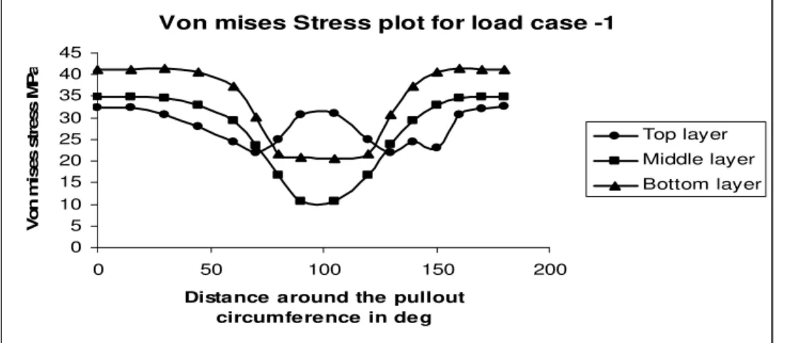
The shell nozzle junction model is analyzed with three load cases as given in table 1. Three locations are considered like extrados, crown and intrados and for each location, three layer stresses are calculated. The von mises stress values are plotted in the form of graph by taking von mises stress in y-axis and the angles around the circumference in x-axis. Half symmetry model is taken for analysis. 0o indicates the value in the extrados and 90o indicates the values in the crown and 180o indicates the value in the intrados. In the following section will discuss in detail the stress values for all the load cases.
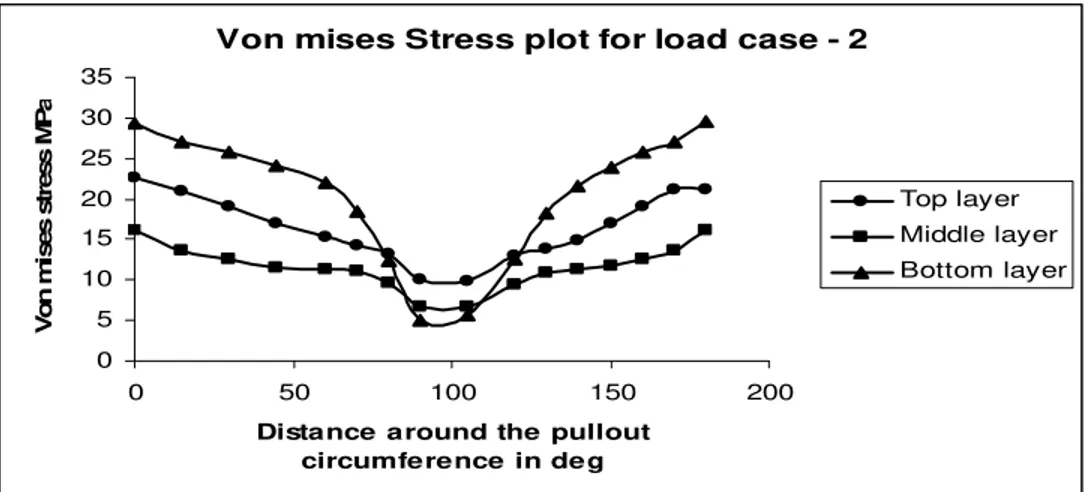
In this load case 1 pressure is applied throughout the inner surface of the model. The von mises stress values for the load case 1 around the circumference is given in the form of graph in figure 10 for all the three layers. From this graph, the maximum stress occurs at the junction of cylindrical shell and the nozzle of both ends of half symmetry shell nozzle junction. The stress value is gradually decreasing through the circumference and increasing again. In load case 2, Moment is applied at the end of the nozzle. The von mises stress plot is shown in figure 11. All the three layers gives maximum stress values at the extrados and intrados and minimum values in the crown portion. In load case 3, pressure is applied throughout the inner surface of the model and the moment is applied at the end of the nozzle. The von mises stress plot is shown in figure 12. All the three layers gives maximum value in the extrados and then the value of stress falls down gradually, the value keeps reducing around the circumference, till it reaches the crown where it falls to the minimum value, and then it gradually rises till it achieves a little higher value
Figure 10 Von mises stress plot for load case -1
Von mises Stress plot for load case -1
0 5 10 15 20 25 30 35 40 45
0 50 100 150 200
Distance around the pullout circumference in deg
V
on m
ise
s st
ress
M
P
a
Top layer Middle layer
Figure 11 Von mises stress plot for load case -2
Figure 12 Von mises stress plot for load case -3
Conclusions
The maximum stress values are obtained from the analysis for all the load cases. From the results of analysis, it can be observed that the maximum stress occurs at the junction of pull out region and the nozzle and maximum displacement occurs in the middle of pullout region. High stress concentration is developed at this location due to abrupt change in the geometry and the consequent change in stress flow. In this location, the crack is formed and can do further analysis.
References
[1] Milne, R.A. Ainsworth, A.R. Dowling, and A.R. Stewart, Assessment of structures containing defects, CEGB Report R/H/R6,1986, Revision 3, Central Electricity Generating Board, UK.A16, “Guide for defect assessment and leak before break,” Rapport DMT 95/659, 1995,third draft.
[2] RCC-MR: Design and construction rules for mechanical components for FBR nuclear islands, Section I, Subsection B, Class 1 Components, AFCEN, 2002.
[3] ASME, Section III, Div 1, Subsection NH, Class 1 Components in elevated temperature service, 2001. [4] ASME, Sec-XI, Rules for inspection and testing of components of liquid-metal cooled plants, 1989.
[5] Ming-De Xue, Qing-Hai Du ,Dong-Feng Li, Keh-Chih Hwang, Theoretical stress analysis of Intersecting Cylindrical Shells subjected to External forces on nozzle, Journal of Pressure vessel Technology, 2006, 128, pp.71-83.
[6] A.R.C.Murthy, An efficient FE modeling strategy for Fracture Analysis of Tubular Joints, IE (I) Journal – CV, 85, pp.17-25, 2004. [7] P.O. Bijlaard, Stresses from local loadings in pressure vessels, Trans. ASME, Vol .77, pp. 805-816, 1955.
[8] O.C. Zienkiwicz, The Finite element Method”, McGraw –Hill, New York, 1989.
Von mises Stress plot for load case - 2
0 5 10 15 20 25 30 35
0 50 100 150 200
Distance around the pullout circumference in deg
V o n m ises st ress M P a Top layer Middle layer Bottom layer
Von mises stress plot for load case -3
0 10 20 30 40 50 60 70
0 50 100 150 200
Distance around the pullout cicumfe re nce in de g
Biographical notes
N.Mani receivedM.E. degree from University of Madras and currently pursuing PhD degree in Anna University, Chennai, India. His research interests include stress analysis, Fracture mechanics and Finite Element Analysis. Dr.G.Thanigaiyarasu working as a Professor in Mechanical Engineering, Anna University, Chennai, India.