Two Axes Solar Tracker Based on Solar Maps,
Controlled by a Low-Power Microcontroller
F. Duarte, P.D. Gasparand L.C. GonçalvesElectromechanical Engineering Department, Engineering Faculty, University of Beira Interior, Covilhã 6201-001, Portugal
Received: July 08, 2010 / Accepted: October 30, 2010 / Published: July 31, 2011.
Abstract: There are actually several solutions for two axis solar tracking systems using electromechanical devices, in which a
controller detects the Sun apparent position, and controls the position of the structure supporting the panels toward the sun by enabling the engines movement. This work studies the solution of two axis solar tracking system based on solar maps, which can predict the exact apparent position of the Sun, by the latitude’s location, thereby avoiding the need to use sensors or guidance systems. To accomplish this, it is used a low-power microcontroller, suitably programmed, to control two electric motors to ensure that the panels supporting structure is always oriented towards the sun.
Key words: Two axis solar tracker, photovoltaic energy, electromechanical system, solar maps, low-power microcontroller.
1. Introduction
The increasing interests in using renewable energies for detached houses are coming from solar thermal energy systems for domestic hot water and solar photovoltaic systems to the micro production of electricity. Most of these applications do not have any solar tracker system, mainly because of its high cost. A two axis solar tracker system can increase the energy conversion by 40%, being a suitable solution to increase the electrical energy output. It seems that a major obstacle to its use is the cost, basically due to the price of the sensors applied to detect the Sun apparent position, and to the control system (mainly with Programmable Logic Controllers—PLCs). Studies concerning the Sun apparent movement concluded that it is possible to predict with accuracy the relative position of the Earth and the place, every day and every hour. This position is described in solar maps, for each location (defined by the location's latitude). Microcontrollers can be used in order to control the
Corresponding author: P.D. Gaspar, assistant professor,
research fields: renewable energy, energy harvesting, refrigeration. E-mail: dinis@ubi.pt.
electric motors. Using the microcontrollers with programmed solar maps for each location (latitude), and defining the date and hour, it is possible to control the angular position of the electric motors drive shafts. This defines the position and orientation of the photovoltaic panels supporting structure.
A two axes solar tracking system, according to several studies [1-10], increases the energy production of approximately 40%. The systems available on market are based on sensors that detect the Sun position. A controller adjusts the structure position (inclination and direction) according to information gathered by sensors, and thus controlling two electric motors. By using this technique, these systems have good accuracy, but are expensive.
The aim of this work consists on the development of a two-axis electromechanical system for sun tracking (detect Sun apparent position), based on solar maps data, with a low energy consumption and lower final cost than the systems available on market.
From literature available related to studies on two axes solar tracking systems [1-10], it is possible to know that recently have been studied the solar tracking technique
by knowing the Sun apparent position, however the control systems operates on a hour basis, without recognizing the month and the consequent effect in the Sun apparent position. The study developed by S. Abdallah and S. Nijmeh [1] shows an increase of 40% of the energy produced, only changing the panels’ position four times a day, and without knowing the month (only by hour).
A more deep knowledge was developed through solar maps study in order to evaluate the Sun apparent position variation according to month and hour, to achieve a more precise control. The analysis of the work developed by [11, 12], allows verifying that solar maps let us know the sun’s apparent position on each day of the year and each hour, according to location (latitude). Thus, a table can be created to gather all information concerning with the Sun apparent position every hour, for each month (as the position does not vary much throughout the month).
After identifying the Sun apparent position and relying on two axes solar tracking systems available on the market [13], using two motors that move the mechanical structure, further control is achieved controlling them using a low power microcontroller, MSP430 device from Texas Instruments, instead of a traditional PLC. Using this low-power microcontroller, together with two electrical motors, properly designed, it is possible to project a solar tracking system without sensors to detect the Sun apparent position, with a very low cost control system, ensuring the maximization of solar power generation.
The study was carried out on installation that supports 10 photovoltaic panels of 200 W each, distributed in two rows of five panels, having a total power of 2 kW. The data used in this work are related to Portuguese solar irradiation.
2. Solar Maps Study and Their Application
for Solar Tracking
Based on astronomical data it is known that the solar energy available on the Earth is very variable. This variation depends on geographic latitude, day and
month for a predetermined location. Summer days are longer than winter days and the solar altitudes for the sun are higher in summer months than in winter due to the inclination of Earth's axis. For different incidence angles of the sun throughout the year, at certain latitude, there is a maximum amount of radiation received, which can be obtained if the receptor surface is inclined at an appropriate angle. The optimum angle for winter months (less radiation) is higher than in summer because of lower solar altitude. Table 1 shows the common angles used in solar technology.
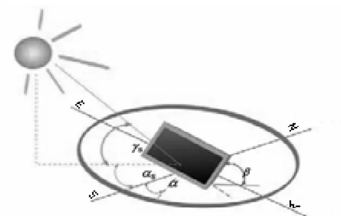
The representation of these angles is shown in Fig. 1. The solar path varies the Sun coordinates throughout the day. This can be seen in Fig. 2, where h is the solar altitude and αs is the solar azimuth angle.
Table 1 Angles used in solar technology.
Angles Values
Solar Height γS H = 0º Z = 90º
Solar Azimuth αS S = 0º E = -90º W = +90º
Superficial Slope β H = 0º V = 90º
Superficial Azimuth α S = 0º E = -90º W = +90º H-Horizontal, S-South, Z-Zenith, E-East, W-West.
Fig. 1 Description of angles for solar technology.
It’s verified that the Sun apparent position relatively to Earth, varies in both height and azimuth at each time. When someone wants to install a solar system, must take special care in selecting the inclination and orientation of the panels, which are the two factors that will have major influence on system’s performance, since these depend on the incoming radiation level.
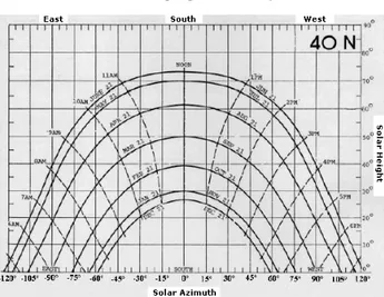
It is possible to determine the Sun coordinates throughout the year using a stereographic projection, or using the curves in Fig. 3. The curves of the sun’s position to a latitude of 40º North (average latitude of Portugal), the slope and solar azimuth for each month, day (reference is 21), and hour are shown in Fig. 4.
Thus, data from Fig. 3 give the Sun position, avoiding the need of sensors to detect it. This can be done by programming a microcontroller with coordinates, and changing hour, day and month, in
Fig. 3 Sun apparent position, according to the month, day and time for latitude 40º North.
Fig. 4 Division by zones of the sun position, according to the month, day and time (latitude 40º North).
order to control the electrical motors regarding the inclination and orientation of the panels’ base structure.
To facilitate the control program, the map of Fig. 3 was divided in several areas, which are marked with one letter and one number, as are shown in Fig. 4.
3. Solar Tracker Electromechanical Project
The electromechanical project is divided into four parts: mechanical design, electrical design, electronic design, and development of the control program.
For the mechanical design it was designed the panels’ support structure, with two degrees of freedom in order to vary the inclination and orientation. Also, the conception of the panels support as well as the system that allows this support to revolve around the two axes was developed.
The tracker consists on a fixed base directly to the ground, having a mechanism that connects the base to the supporting structure of the panels. This mechanism consists of two parts, which have a degree of freedom from each other (linked by a shaft on X axis), changing the inclination of the structure (between 10 and 75º). Additional links are mounted for motors and other components of the solar tracker control system. The physical connection between this mechanism and the panels’ support structure has a degree of freedom, being these parts connected by a shaft on Y axis.
The control of the panels’ support structure orientation is done by an electrical motor driving a worm screw system. This system is linked to the structure through a motor shaft, a worm screw and a belt reduction system with gearbox. The mechanical system allows that Z1 rotations of the electrical motor
correspond to Z2 turns of the worm screw, that
corresponds to Xº variation. This system is used between the binding mechanism of the panels’ base support structure and the structure. A damper is also applied to ensure the structure safety in case of adverse weather conditions. The control of the slope (inclination) is done in a similar way: electrical motor connected to the worm screw system by a belt reduction system with gearbox and applied between the
pieces of the structure’s binding mechanism. Only the damper is used between this mechanism and the panels’ support structure. To apply the worm screw system, which controls the movement (direction and inclination) of the panels’ support structure, two AC electrical motors, single phase, were selected with a supply voltage of 220 V and a power of 750 W each.
The projected solar tracker is shown in Fig. 5. To each motor shaft is attached a gear wheel with Z1
sprocket, being this connected to a second gear, with Z2
sprocket, which is fixed to the part that runs on the worm screw. This second gear has a magnet fixed to it, which will be used as a reference point for a magnetic sensor placed at a fixed point to count the wheel turns (hence the worm screw turns).
Each turn of the part on the worm screw, corresponds to a 1º rotation angle of the panel. The motor will be going into operation in the way that causes a movement in the desired direction. The number of turns, counted by the sensor, corresponds to the desired difference of degrees.
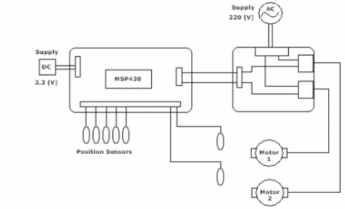
To perform the control of the solar tracker, the MSP430 F449 STK2 development kit which uses a Texas Instruments microcontroller was used. Four sensors are connected to indicate the panels limit positions of the minimum (10) and maximum (75) inclination, and the minimum (75E) and maximum (75O) direction.
The microcontroller will control two selected AC motors, sending the digital signal “1” for an adapter that converts into 220 V to supply the electrical motors in order to rotate in the desired direction and the necessary number of turns. The wiring diagram is shown in Fig. 6.
The control is accomplished by connecting the MSP pins (selected as outputs) to the digital inputs of the interface plate. The dry contact relays type (220 V) output pins of this PCB are connected to the electrical drive (along with ground wire).
Two magnetic sensors are also connected, to count the turns, through the detection of the magnet fixed to
Fig. 5 Solar tracker (base, control mechanism, support structure of the panels).
Fig. 6 Electrical scheme of the control system.
the wheel that operates the worm screw movement. These inductive proximity sensors are based on its impedance variation with the proximity of metal objects (in this case, a magnet). Placing a conductive metal inside the sensor’s detection area (a few millimetres) Eddy currents appear inside the metallic material. This phenomenon changes the magnetic field generated, resulting in an impedance variation of the sensor. So, the current intensity within the sensor varies, being measured by a current detector placed inside, which controls the transistor (operating as a switch) and drives the output. Additionally, a sensor to detect the zero position of the solar panels is applied (0º orientation - South).
All sensors operate at 3.3 V, being supplied by the MSP power (of 3.3 V) are normally open inputs (returning 0 V). In the case of detecting the proximity of the magnet (for magnetic sensors), or at the final
positions, they returns the voltage 3.3 V at the other end, which is connected to the correspondent MSP port (high level input).
4. Microcontroller Program
The described control is function of time and month. Thus, the first part of the program must be the creation of a clock and a calendar. The clock counts the seconds, minutes, hours, days, and even months. Using the solar maps previous referred, it is possible to know the sun position every hour (height and inclination) for each month. The map data saved in the microcontroller program is referred to the position 40º North latitude (average latitude of Portugal). The maps and program can be easily adapted for other latitude locations, making the system applicable in any location.
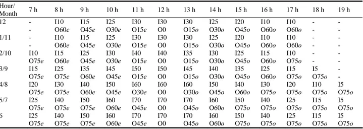
With the clock running, the electrical motors control drives the panels’ support structure to the desired position. The electrical motors should run at each hour, in order to orientate the panels’ support structure to the position obtained from the solar map. To do this control, we must know that the characteristics of the developed structure allow the movement from 75º East to 75º West (Orientation), and 10º to 75º (Inclination) only. The results of this study are presented in Table 2. The months are in numbers, where 1 represents January, to December represented by 12. The inclination angle is I. The orientation angle is O. The East orientation is e while the West orientation is o.
Motor 1 and 2 control respectively orientation and inclination. To control the rotation of each motor, the ratio of sprockets was adjusted so that to one turn of the sprocket corresponds to the displacement of 1º of the panel (either in direction or inclination).
A magnet is applied in the gear wheel to count its turns, and a magnetic sensor detects each passage, sending that information to the MSP. A routine is set in the program for each sensor, which allows counting the turns. This routine should increment the variable “turnX” (turn1 for motor 1 and turn2 for motor 2), each time the pin connected to the sensor presents a “high” level. Two encoders are created to calculate the number of turns, that is, the number of degrees that each motor has displaced the panel’s structure.
To start the program should be introduced the actual hour, minute, day and month values, and the running start process should be done between 23:01 and 6:55, when the panels structure is on the standard position (Inclination = 10º and direction = South). This is due to the standard position, starting from 7 am programmed in the motor control code.
At 23 o’clock of each day it commands the panel’s structure to the standard position, knowing that this is in the limit. Starting at 7 o’clock, and depending on the month, the microcontroller sends commands every hour to the motors, to move them in the desired direction, and the number of turns programmed.
With this control, the structure will be orientated to
Table 2 Inclination (I in degrees) and orientation (O in degrees: East: e; West: o) of the panel, at each hour of the month.
Hour/ Month 7 h 8 h 9 h 10 h 11 h 12 h 13 h 14 h 15 h 16 h 17 h 18 h 19 h 12 - - I10 O60e I15 O45e I25 O30e I30 O15e I30 O0 I30 O15o I25 O30o I20 O45o I10 O60o I10 O60o - - - - 1/11 - - I10 O60e I15 O45e I25 O30e I30 O15e I30 O0 I30 O15o I25 O30o I20 O45o I10 O60o I10 O60o - - - - 2/10 I10 O75e I15 O60e I25 O45e I30 O30e I40 O15e I40 O0 I35 O15o I30 O30o I25 O45o I15 O60o I10 O75o - - - - 3/9 I15 O75e I25 O75e I35 O60e I45 O45e I50 O15e I50 O0 I45 O15o I40 O30o I35 O45o I25 O60o I15 O75o I5 O75o - - 4/8 I20 O75e I30 O75e I40 O60e I50 O45e I60 O30e I60 O0 I60 O30o I50 O45o I40 O60o I30 O75o I20 O75o I10 O75o I5 O75o 5/7 I25 O75e I40 O75e I50 O75e I60 O60e I70 O45e I70 O0 I70 O45o I60 O60o I50 O75o I40 O75o I25 O75o I15 O75o I5 O75o 6 I25 O75e I40 O75e I50 O75e I60 O60e I70 O45e I70 O0 I70 O45o I60 O60o I50 O75o I40 O75o I25 O75o I15 O75o I5 O75o
the sun with a high precision at each hour between 8 and 16 o’clock every year. The precision in summer time, after 16 o’clock, will not be the best due to the limitation of the orientation angle (75E-75W). Nevertheless, the orientation allows a better efficiency than a fixed system.
5. Conclusions
The main contributions of this work are the development of a two axes solar tracker that does not use any sensor to predict the Sun apparent position. It makes use of a solar map with the Sun coordinates, depending on the hours and months. Saving the solar map of the location in the microcontroller program where the system will be installed allows to use it anywhere. It also uses a simplified and low power microcontroller that includes a simple user interface for the solar installation owner.
The proposed solar tracking system will be reliable and accurate throughout the year, maximizing the efficiency of energy conversion. It will be a good and competitive solution for the marketplace as it is expected to compete with more complex and expensive systems. The main application of the solar tracker system will be low power solar applications (micro-production systems) due to the panels’ limit number in the structure (maximum of 10 panels).
References
[1] S. Abdallah, S. Nijmeh, Two axes sun tracking system with PLC control, Energy Conversion and Management 45
(2004) 1931-1939.
[2] V. Poulek, M. Libra, New solar tracker, Solar Energy Materials and Solar Cells 51 (1998) 113-120.
[3] T. Tomson, Discrete two-positional tracking of solar collectors, Renewable Energy 33 (2008) 400-405. [4] M.J. Clifford, D. Eastwood, Design of a novel passive
solar tracker, Solar Energy 77 (2004) 269-280.
[5] G.C. Bakos, Design and construction of a two-axis Sun tracking system for parabolic trough collector (PTC) efficiency improvement, Renewable Energy 31 (2006) 2411-2421.
[6] P. Roth, A. Georgiev, H. Boudinov,Cheap two axis sun following device, Energy Conversion and Management 46 (2005) 1179-1192.
[7] A. Mellit, S.A. Kalogirou, Artificial intelligence techniques for photovoltaic applications: A review, Progress in Energy and Combustion Science 34 (2008) 574-632.
[8] F.R. Rubio, M.G. Ortega, F. Gordillo, M. Lo´pez-Martı´nez, Application of new control strategy for sun tracking, Energy Conversion and Management 48 (2007) 2174-2184.
[9] H. Mousazadeh, A. Keyhani, A. Javadi, H. Mobli, C. Abrinia, A. Sharifi, A review of principle and sun-tracking methods for maximizing solar systems output, Renewable and Sustainable Energy Reviews 13 (2009) 1800-1818. [10] N.A. Kelly, T.L. Gibson, Improved photovoltaic energy
output for cloudy conditions with a solar tracking system, Solar Energy 83 (11) (2009) 2092-2102.
[11] J.C. Costa, Solar thermal facilities, Instituto Nacional de Engenharia, Tecnologia e Inovação – INETI (National Institute of Engineering, Technology and Innovation), 2007. (in Portuguese)
[12] J.C. Costa, Solar thermal energy, Instituto Nacional de Engenharia, Tecnologia e Inovação – INETI (National Institute of Engineering, Technology and Innovation), 2007. (in Portuguese)