Abstract—The purpose of this study is the development of an admittance motion command generator for controlling the motion of a robotic walking support system used to guide a user walking at a uniform or user-adjustable walking velocity along a preplanned walking path, as illustrated by parametric spline functions. The correlation between a preplanned walking path and the force exerted by a user is usually complicated and indirect because of the high nonlinearity of parametric spline functions. Therefore, an interpolation algorithm based on Taylor’s expansion is developed in this study to correlate the preplanned walking path with a desired linear velocity. When the desired linear velocity is set as a uniform walking velocity command, the robotic walking support system can guide a user walking along a preplanned walking path at uniform walking velocity. Furthermore, for the robotic walking support system to be able to guide the user at user-adjustable walking velocity, the concept of admittance motion control is employed to correlate the desired linear velocity with the force exerted by the user. Several experiments are conducted using a robotic cane that was developed in this study, and the experimental results show the validity of the proposed approaches.
Index Terms—motion control, robotic walking support system, admittance control, motion command generator
I. INTRODUCTION
EOPLE whose lower limbs are in normal condition but who face difficulty walking usually use walkers or canes to help them walk. Such devices are usually used by people to maintain their balance, support their weight, train a person to walk, and increase the muscle strength of a user’s lower limbs. Although these devices aid mobility, they are considered to be passive devices, and users must have motion abilities to use these devices. Therefore, in recent decades, robotic technologies have been applied to conventional walking support devices; the resulting robotic walking support systems provide significantly improved walking-assistance.
Lacey and Dawson-Howe [1] described the application of mobile robot technology to provide mobility aid for the blind;
Manuscript received January 7, 2011. This work was supported in part by the National Science Council of the Republic of China under Contract NSC 99-2221-E-027-009 and the Industrial Technology Research Institute of the Republic of China under project number 9353C72000, which is subcontracted from the Ministry of Economic Affairs, Taiwan.
Yong-Zeng Zhang is with the Institute of Mechatronic Engineering, National Taipei University of Technology, Taipei, Taiwan (e-mail: [email protected]).
Syh-Shiuh Yeh is with the Department of Mechanical Engineering, National Taipei University of Technology, Taipei, Taiwan (phone: +886-2-2771-2171; fax: +886-2-2731-7191; e-mail: [email protected]).
further, the PAM-AID mobile robot [2], consisting of a walking frame with wheels, was developed to help avoid obstacles and physically support a person while walking. To help the elderly live independently in private living environments, a robotic assistant called Care-O-Bot II [3][4] was developed with adjustable walking supports to support and guide elderly people safely in indoor environments. Hirata et al. [5][6] proposed a passive intelligent walker, called the RT Walker, to assist elderly and handicapped people to walk in both indoor and outdoor environments. The developed adaptive motion control algorithm enables the RT Walker to adapt to user operation, and the walker helps avoid obstacles on the basis of extracted environmental information. Chuy Jr. et al. [7][8][9] developed the Walking Helper; this device considers user operation characteristics to aid users in controlling their walking support system. Further, Chuy Jr. et al. [10] developed a motorized robotic walking support system based on the passive behavior concept proposed by Hirata et al. [5] to enhance interaction between the walking support system and the user. Wasson et al. [11] presented an operation system that can determine a user’s navigational intent by measuring the forces and moments acting on the handles of the walker. Morris et al. [12] proposed a robotic walker that integrates a haptic interface and a robot localization and navigation system to provide mobility assistance to frail elderly people with cognitive impairment. Sabatini et al. [13] developed a motorized rollator equipped with force, ultrasonic, and infrared sensors to support elderly people and avoid collisions while walking. Chugo et al. [14] developed a robotic walker system that combines standing and walking assistance functions by using an assistance manipulator and an active walker to provide standing, walking, and seating assistance for the elderly. Spenko et al. [15] developed a smart walker that provides support, guidance, and health monitoring for the elderly in an assisted living facility. This smart walker uses a six-axis force/torque sensor attached to the walker’s handle as the main control input interface. Furthermore, a shared adaptive control algorithm was developed to control the smart walker by a computer controller, allowing the smart walker to gently guide the user. Spenko et al. [15] also developed a smart cane that provides functions similar to those of the smart walker. Although some cane robots such as the Walking Guide Robot [16], RoJi Robot [17], GuideCane Robot [18], and the Robotic Cane proposed by Aigner and McCarragher [19] can provide good guiding performances for the visually impaired and the elderly, they cannot physically support the elderly during walking.
Motion Control Design for Robotic Walking
Support Systems Using Admittance Motion
Command Generator
Yong-Zeng Zhang and Syh-Shiuh Yeh
In the developed robotic walking support systems, several functions such as walking guidance, obstacle avoidance, localization and navigation, and health monitoring are normally realized in order to provide better walking assistance to users. Moreover, some studies have focused on the physical interaction between the user and a robotic walking support system in order to provide users with a stable and convenient manipulation interface. Among the existing robotic walking support systems, the functionality of walking guidance is fundamental because robotic walking support systems are usually used to guide a user walking toward a goal position in a living environment. The motions of a robotic walking support system used for walking guidance could also affect the walking behavior of the user. However, the walking guidance functionalities of the existing robotic walking support systems usually guide a user walking in the commanded direction at an arbitrary velocity. Therefore, in order to smoothly guide a user walking from one position to another along a preplanned walking path with a uniform or user-adjustable motion velocity, a motion command generator must generate uniform or user-adjustable velocity commands to control the robotic walking support system. This indicates that the motion command generator of a robotic walking support system must correlate the preplanned walking path with the force exerted by the user. In this study, the correlation between the walking path and a desired linear velocity is developed first; then, the correlation between the desired linear velocity and the force exerted by the user is developed to complete the correlation between the preplanned walking path and the force exerted by the user.
Parametric spline functions such as the B-spline function [20], Beta-spline function [21], and polynomial function [22][23] are used for path planning in robotics. Thus, a parametric spline function is used to illustrate the preplanned walking paths in this paper. Here, the walking paths are preplanned in advance according to the walking environments of the user in order to guide the user when walking from one position to another. Because of the highly nonlinear properties of parametric spline functions, in order to correlate the walking path with a desired linear velocity, an interpolation algorithm based on Taylor’s expansion [24] is developed in this study. By applying the developed interpolation algorithm, the robotic walking support system can guide the user walking along a preplanned walking path at a uniform walking velocity. In addition, in order to further make the robotic walking support system guide the user along a preplanned walking path with a user-adjustable motion velocity, it is necessary to correlate the desired linear velocity with the force exerted by the user. Impedance control [25] and admittance control [26][27] are frequently used control methods to correlate the velocity and force characteristics of mechanical systems. Zeng and Hemami [28] compared these control methods in detail. Admittance control can be applied to control mechanical systems with friction, backlash, and heavy mass, and is typically applied to control mechanical systems with position/speed-controlled actuators, which are also used in the experimental setup in this study. Therefore, in this study, the admittance control law design concept is employed to correlate the desired linear velocity with the force exerted by the user. By integrating the admittance control law design concept into the developed interpolation algorithm, the resulting admittance motion command generator can generate velocity commands that directly relate
to the force exerted by the user, for controlling a robotic walking support system. Thus, the robotic walking support system can guide a user walking along a preplanned walking path with a user-adjustable motion velocity.
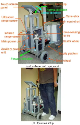
In this study, a robotic walking support system, the robotic cane, is developed as experimental system to show the validity of the proposed approaches. This robotic cane is composed of a two-wheeled mobile platform, a cane-stick, and a biaxial force-sensing device that was developed to estimate the force exerted by the user of the robotic cane. Several simulations and experiments are performed on the robotic cane and the experimental results show the validity of the admittance motion command generator developed in this study.
II. DESCRIPTIONS OF THE EXPERIMENTAL SYSTEM (THE ROBOTIC CANE)
(a) Hardware and equipment
(b) Operation setup Fig. 1. The robotic cane.
III. DESIGN OF THE ADMITTANCE MOTION COMMAND GENERATOR
Fig. 2 illustrates the motion control structure developed in this study for controlling the motions of the robotic cane so that it can guide a user walking along a preplanned walking path with a uniform or user-adjustable walking velocity. The path generator generates a preplanned walking path in advance based on the walking environment of the user in order to guide the user when walking from one position to another. Because the preplanned walking path is defined by a parametric spline function in this study, an interpolation algorithm is required to generate linear and angular velocity commands for the motion control law that generates servo commands for driving the left and right drive wheels of the robotic cane. Here, the interpolation algorithm must refer to a desired linear velocity so that the linear velocity command for the motion control law can be equivalent to the desired linear velocity. In this study, the user can set a uniform walking velocity command from the touch-screen panel so that the robotic cane guides the user at a uniform walking velocity. Moreover, the user can switch to another guiding mode that allows the robotic cane to guide the user at a user-adjustable walking velocity. The biaxial force-sensing device is used to estimate the force exerted by the user and the low-pass filter is used to characterize the motions of the robotic cane. The desired linear velocity is taken from either the uniform walking velocity command or the output of the low-pass filter, depending on the switch command. In this study, because of the highly nonlinearity of the parametric spline function,
Taylor’s expansion [24] is applied to correlate the preplanned walking path and the desired linear velocity.
Fig. 2. The developed motion control structure.
In this study, the walking paths are defined by a parametric spline function C
( )
u and the spline parameter u is a time function. Thus, the approximation of u can be obtained by using the Taylor’s expansion [24], as:(
t t)
HOTdt du u
u i i
t t i i
i
. . 1
1 = + ⋅ + − +
=
+ , (1)
where ui denotes the value of u at time t=ti and ui+1
denotes the value of u at time t=ti+1. The symbol H.O.T
denotes the higher order terms of the Taylor’s expansion. Let the time step in the interpolation be Ts seconds, and thus
s i
i t T
t+1− = . By neglecting the higher order terms (H.O.T.) in
Eq. (1), we can rewrite Eq. (1) as:
s t t i
i T
dt du u u
i
⋅ + =
=
+1 . (2)
Eq. (2) can be used to interatively compute the interpolated positions on the walking path, C
( )
u . For instance, interpolated position C(ui+1) is obtained by substituting spline parameter ui+1 into function C( )
u . Here, as shown inEq. (2), spline parameter ui+1 is obtained from the given ui,
i t t
dt du
=
, and Ts. Similarly, the interpolated position C(ui) is
obtained by substituting spline parameter ui into function
( )
uC , and spline parameter ui is obtained from the given
1
− i
u ,
1 − =ti t
dt du
, and Ts. Moreover, the motion speed of the
robotic cane depends on the derivative value of spline parameter u with respect to time t. For instance, the motion speed of the robotic cane from interpolated position C(ui) to
) (ui+1
C depends on the value of
i t t dt du
=
. Therefore, in order
to make the robotic cane move on the walking path at a desired linear velocity, it is necessary to correlate the desired linear velocity with the derivative value of spline parameter u with respect to time t.
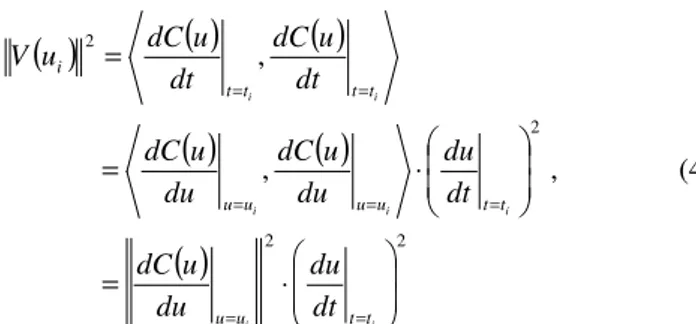
Since the spline velocity, V
( )
u , can be obtained as:( )
( )
( )
dt du
du u dC
dt u dC u
and
( )
( )
( )
( )
( )
( )
2 22 2 , , ⋅ = ⋅ = = = = = = = = = i i i i i i i t t u u t t u u u u t t t t i dt du du u dC dt du du u dC du u dC dt u dC dt u dC u V , (4)
the derivative value of spline parameter u with respect to time t at time ti can be obtained as:
( )
( )
i i u u i t t du u dC u V dt du = == for
( )
≠0=ui
u du
u dC
, (5)
where ⋅ ,⋅ is an inner product operator and ⋅ is the
Euclidean norm operator. In this study, the desired linear
velocity, vd, replaces the magnitude of the spline velocity,
( )
uiV , in order to correlate vd and V
( )
ui . Therefore, Eq.(5) is rewritten as:
( )
i i u u d t t du u dC v dt du = == for
( )
≠0=ui u
du u dC
, (6)
and Eq. (2) becomes:
( )
i u u s d i i du u dC T v u u = + ⋅ + =1 for
( )
0
≠
=ui u
du u dC
. (7)
Since Eq. (7) interpolates the walking path, C
( )
u , with thedesired linear velocity, vd, Eq. (7) is the interpolation
algorithm used is this study. Therefore, for the given vd, Ts,
and
( )
i u u du u dC =
, the interpolation algorithm, Eq. (7), not
only interatively computes the interpolated positions on the
walking path, C
( )
u , but also approximates the motion speedof the robotic cane to the desired linear velocity, vd.
In order to generate the linear and angular velocity commands for the motion control law of the robotic cane at
time t=ti, the interpolated position, C(ui+1), must be
calculated using the interpolation algorithm in Eq. (7). Fig. 3
shows the interpolated positions, C(ui−1), C(ui), and
) (ui+1
C , on a walking path, C
( )
u .Fig. 3. The successive interpolated positions on a walking path.
In Fig. 3, αi and βi respectively denote the distance and
the angle between adjacent interpolated positions C(ui) and
) (ui+1
C . Here, the length, αi, and the angle, βi, are
computed by ) ( )
( 1
i= C ui+ −C ui
α ) ) ( ) ( ) ( ) ( ] ) ( ) ( [ )] ( ) ( [ ( sin 1 1 1 1 1 i i i i i i i i i u C u C u C u C u C u C u C u C − ⋅ − − × − = + − + − − β ,
where × is a cross product operator. Thus, the linear velocity
command, v(t), and the angular velocity command, θ(t), at
time t=ti are obtained as:
s t t i T t v t v i i ) ( )
( = = =α (8)
s t t i T t t i i ) ( )
( θ β
θ = =
= , (9)
where Ts is the time step in the interpolation and is also the
sampling period in the motion control system of the robotic cane.
In this study, by setting the desired linear velocity, vd, as
the uniform walking velocity command, as shown in Fig. 2, the robotic cane guides the user with a uniform walking velocity. In order to make the robotic cane guide the user with a user-adjustable walking velocity, the desired linear velocity,
d
v , must be a function of the force exerted by the user. Since
the equivalent force, Fapp, exerted by the user can be
estimated by using the biaxial force-sensing device, the
desired linear velocity, vd, is thus determined in this study by:
) ( app d f F
v = . (10)
Here, function f(⋅) affects the motions of the robotic cane. The simplest function is a constant gain. For a function with a large constant gain, the user can drive the robotic cane by exerting a small force on the force-sensing device. However, the motions of the robotic cane become sensitive to the motions of the user’s hand. This causes the motions of the robotic cane to be problematic for some users with hand vibrations. For a function with a small constant gain, the user must drive the robotic cane by exerting a large force on the force-sensing device, and thus the motions of the robotic cane become less sensitive to the motions of the user’s hand. Therefore, a low-pass filter with an adjustable gain and bandwidth is employed in this study. The low-pass filter can reduce the vibrations induced by the user’s hand, and can also adjust the motion sensitivity of the robotic cane.
IV. EXPERIMENTAL RESULTS
user-adjustable walking velocity. During the period from time-point “c” to time-time-point “d”, the user changes the linear velocity command through the use of the force-sensing device, such that the robotic cane guides the user walking with the user-adjustable walking velocity along the preplanned walking path. At time-point “e”, the user again switches the operation mode so that the movement of the robotic cane is based on the uniform walking velocity command. The linear velocity command thus gradually increases to 10.0 cm/sec. Fig. 4(b) and Fig. 4(c) show the linear and angular velocities of the robotic cane in the experiment, respectively.
(a) The preplanned walking path
(b) The linear velocity of the motion
(c) The angular velocity of the motion Fig. 4. Experimental results for an even walking surface.
As shown in Fig. 4(b), the robotic cane moves with a linear velocity response that is similar to the uniform walking velocity command during the period from the start to time-point “a”. Here, the linear velocity response is fluctuant because of the disturbance induced by the contact between the drive wheels of the robotic cane and the walking surface. During steady motions (the period from 15 seconds to 30 seconds), the average value of the linear velocity response is 9.9363 cm/sec and the variance is 0.0099 cm/sec, which is 0.1% of the average value. Because the robotic cane is turning during this period, the angular velocity command is varying and the maximum value is 0.3270 rad/sec. The angular velocity response follows the angular velocity command and the maximum value of absolute following error is 0.0279 rad/sec. In the experiment, even though the linear velocity commands are zero in the periods from “b” to “c” and from “d” to “e”, the robotic cane moves with slow velocities
because of the long settling time of the linear velocity response. However, reducing the settling time usually increases the maximum overshoot of the linear velocity response. During the period from “c” to “d”, the robotic cane moves along the preplanned walking path with a user-adjustable walking velocity. The admittance motion command generator generates the linear velocity command based on the force exerted by the user. Fig. 4(b) also shows the measured voltage of the force-sensing device. Here, a first-order Butterworth low-pass filter with a bandwidth of 1.0 rad/sec and a gain of 0.45 cm/sec/N is applied to the experiment. The linear velocity response follows the linear velocity command and the maximum value of absolute following error is 0.2101 cm/sec. Because the walking path is linear during this period, the angular velocity command is zero and the angular velocity response is fluctuant near zero. The average value of the angular velocity response is 0.0014 rad/sec and the variance value is 5
10 2812 .
2 × − rad/sec. Fig.
4(a) also shows the actual walking path of the robotic cane in the experiment. Although the robotic cane deviates from the preplanned walking path and the maximum value of absolute deviation is 7.3958 cm, the robotic cane guides the user walking along the preplanned walking path defined by a parametric spline function with a uniform or user-adjustable walking velocity.
V. CONCLUSION
velocity, which can be switched by the user. Some simulations and experiments were conducted on the robotic cane. The simulation results show that the developed interpolation algorithm generates the linear and angular velocity commands for the motion control law of the robotic cane based on the desired linear velocity and the preplanned walking path. Moreover, the generated linear velocity command provides a good approximation to the desired linear velocity. The experimental results show that the robotic cane guides a user walking along a preplanned walking path, defined by a parametric spline function, at either a uniform or user-adjustable walking velocity. Therefore, the simulation and experimental results show the validity of the approaches proposed in this study.
REFERENCES
[1] G. Lacey and K. M. Dawson-Howe, “The Application of robotics to a mobility aid for the elderly blind,” Robotics and Autonomous Systems, vol. 23, no. 4, pp. 245–252, 1998.
[2] S. MacNamara and G. Lacey, “A Smart walker for the frail visually impaired,” Proc. of the 2000 IEEE International Conference on Robotics and Automation, vol. 2, pp. 1354–1359, 2000.
[3] B. Graf, M. Hans, and R. D. Schraft, “Care-O-bot II - Development of a Next Generation Robotic Home Assistant,” Autonomous Robots, vol. 16, no. 2, pp. 193–205, 2004.
[4] B. Graf and R. D. Schraft, “Behavior-based path modification for shared control of robotic walking aids,” Proc. of the 10th IEEE International Conference on Rehabilitation Robotics, pp. 317–322, 2007.
[5] Y. Hirata, A. Hara, and K. Kosuge, “Motion control of passive intelligent walker using servo brakes,” IEEE Transactions on Robotics, vol. 23, no. 5, pp. 981–990, 2007.
[6] Y. Hirata, H. Song, Z. Wang, and K. Kosuge, “Structural design for omni-directional mobile base of passive-type mobile robot,” Proc. of the IEEE International Conference on Mechatronics and Automation, pp. 192–197, 2007.
[7] O. Chuy Jr., Y. Hirata, and K. Kosuge, “Online approach in adapting user characteristic for robotic walker control,” Proc. of the 2005 IEEE 9th International Conference on Rehabilitation Robotics, vol. 2005, pp. 139–142, 2005.
[8] O. Chuy Jr., Y. Hirata, and K. Kosuge, “A new control approach for a robotic walking support system in adapting user characteristics,” IEEE Transactions on Systems, Man and Cybernetics Part C: Applications and Reviews, vol. 36, no. 6, pp. 725–733, 2006.
[9] O. Chuy Jr., Y. Hirata, and K. Kosuge, “Environment feedback for robotic walking support system control,” Proc. of the IEEE International Conference on Robotics and Automation, pp. 3633– 3638, 2007.
[10] O. Chuy Jr., Y. Hirata, Z. Wang, and K. Kosuge, “A control approach based on passive behavior to enhance user interaction,” IEEE Transactions on Robotics, vol. 23, no. 5, pp. 899–908, 2007. [11] G. Wasson, P. Sheth, M. Alwan, K. Granata, A. Ledoux, and C. Huang,
“User Intent in a Shared Control Framework for Pedestrian Mobility Aids,” Proc. of the 2003 IEEE International Conference on Intelligent Robots and Systems, vol. 3, pp. 2962–2967, 2003.
[12] A. Morris, R. Donamukkala, A. Kapuria, A. Steinfeld, J. T. Matthews, J. Dunbar-Jacob, and S. Thrun, “A robotic walker that provides guidance,” Proc. of the 2003 IEEE International Conference on Robotics and Automation, vol. 1, pp. 25–30, 2003.
[13] A. M. Sabatini, V. Genovese, and E. Pacchierotti, “A mobility aid for the support to walking and object transportation of people with motor impairments,” Proc. of the 2002 IEEE International Conference on Intelligent Robots and Systems, vol. 2, pp. 1349–1354, 2002. [14] D. Chugo, W. Mastuoka, S. Jia, and K. Takase, “The wheel control of a
robotic walker for standing and walking assistance with stability,” Proc. of the 17th IEEE International Symposium on Robot and Human Interactive Communication, pp. 297–302, 2008.
[15] M. Spenko, H. Yu, S. Dubowsky, “Robotic personal aids for mobility and monitoring for the elderly,” IEEE Transactions on Neural Systems and Rehabilitation Engineering, vol. 14, no. 3, pp. 344–351, 2006. [16] M.-J. Yoon, K.-H. Yu, J.-H. Kang, and N.-G. Kim, “Walking guide
robot with tactile display for the blind,” Proc. of the SPIE - The
International Society for Optical Engineering, vol. 6040, ICMIT 2005: Mechatronics, MEMS and Smart Materials, pp. 60402A, 2005. [17] I. Shim, J. Yoon, and M. Yoh, “A human robot interactive system
‘RoJi’,” International Journal of Control, Automation and Systems, vol. 2, no. 3, pp. 398–405, 2004.
[18] S. Shoval, I. Ulrich, and J. Borenstein, “Robotics-Based Obstacle-Avoidance Systems for the Blind and Visually Impaired: NavBelt and the GuideCane,” IEEE Robotics and Automation Magazine, vol. 10, no. 1, pp. 9–20, 2003.
[19] P. Aigner and B. McCarragher, “Shared control framework applied to a robotic aid for the blind,” Proc. of the 1998 IEEE International Conference on Robotics and Automation, vol. 1, pp. 717–722, 1998. [20] D. H. Shin and A. Ollero, “Mobile robot path planning for fine-grained
and smooth path specifications,” Journal of Robotic Systems, vol. 12, no. 7, pp. 491–503, 1995.
[21] F. Gomez-Bravo, F. Cuesta, A. Ollero, and A. Viguria, “Continuous curvature path generation based on β-spline curves for parking maneuvers,” Robotics and Autonomous Systems, vol. 56, no. 4, pp. 360–372, 2008.
[22] C. Guarino Lo Bianco, A. Piazzi, and M. Romano, “Smooth motion generation for unicycle mobile robots via dynamic path inversion,” IEEE Transactions on Robotics, vol. 20, no. 5, pp. 884–891, 2004. [23] A. Piazzi, C. Guarino Lo Bianco, and M. Romano, “η3-Splines for the
smooth path generation of wheeled mobile robots,” IEEE Transactions on Robotics, vol. 23, no. 5, Special Issue on Human-Robot Interaction, pp. 1089–1095, 2007.
[24] G. B. Arfken and H. J. Weber, Mathematical Methods for Physicists, Elsevier Inc., California, 2005.
[25] N. Hogan, “Impedance control: an approach to manipulation, Part I, II, III,” Transactions of the ASME, Journal of Dynamic Systems, Measurement, and Control, vol. 107, pp. 1–24, 1985.
[26] D. E. Whitney, “Force feedback control of manipulator fine motions,” Transactions of the ASME, Journal of Dynamic Systems, Measurement, and Control, vol. 99, pp. 91–97, 1977.
[27] W. S. Newman, “Stability and performance limits of interaction controllers,” Transactions of the ASME, Journal of Dynamic Systems, Measurement, and Control, vol. 114, pp. 563–570, 1992.
[28] G. Zeng and A. Hemami, “An overview of robot force control,” Robotica, vol. 15, pp. 473–482, 1997.
[29] R. Siegwart and I. R. Nourbakhsh, Introduction to autonomous mobile robots, The MIT Press, Cambridge, 2004.