49
AN EXPERIMENTAL INVESTIGATION OF CUP SAND SUSPENSION
FOR AUTOMOBILES
R. Harikrishnan1, M. Jaivignesh2 & B. VijayaRamnath3[*] 1
U.G Student, Department of Mechanical Engineering, Sri Sai Ram Engineering College, Sai Leo Nagar, West Tambaram, Chennai – 600 044, India,[email protected]
2
U.G Student, Department of Mechanical Engineering, Sri Sai Ram Engineering College, Sai Leo Nagar, West Tambaram, Chennai – 600 044, India, [email protected]
3
Professor, Department of Mechanical Engineering, Sri Sai Ram Engineering College, Sai Leo Nagar, West Tambaram, Chennai – 600 044,India,[email protected]
ABSTRACT
Suspension is the term given to the system of springs, shock absorbers and linkages that connects a vehicle to its wheels. Suspension systems serve a dual purpose – contributing to the vehicle‘s road holding / handling and braking for good active safety and driving pleasure, and keeping vehicle occupants comfortable and reasonably well isolated from road noise, bumps and vibrations, etc. At present, coil and leaf type suspensions are used in automobiles. This paper proposes design and fabrication of a suspension called ‗cup sand suspension. In all suspension systems damper is used which acts as a major shock absorber. Generally in automobile suspensions gas or oil is used as damper medium but cup suspension developed in this paper uses fine grains of sand which is a natural damper and it is a low cost best damper too. The suspensions used in automobiles are only compression suspensions but the cup suspension is provided with both compression and expansion action. Possibility of leakage is comparatively less as sand is used as the damper medium. Failure due to the sudden application of load(Buckling) is avoided. Both compression and expansion of springs takes place. Manufacturing cost is less and maintenance cost is less sand is readily and easily available.
Keywords: Cup Suspension, automobiles, damper, sand, cost, design and analysis.
1. INTRODUCTION
Suspension systems contribute to the car‘s contact with the road surface as much as possible because all the forces acting on the vehicle do so through the contact patches of the tires. The suspension also protects the vehicle itself and any cargo or luggage from damage and wear. The design of front and rear suspension of a car may be different. The job of a car suspension is to maximize the friction between the tires and the road surface to provide steering stability with good handling and to ensure the comfort of the passengers. The suspension also protects the vehicle itself and any cargo or luggage from damage and wear. Many factors are important in the accurate design of the suspension system in automobiles. Road holding and braking for good active safety and driving pleasure and keeping vehicle occupants comfortable and reasonably well-isolated from road nose bumps and vibrations etc. are the goals of a suspension system. These goals are generally at odds so the tuning of suspensions involves finding the right compromise. The main draw back in existing coil suspension is a factor called ‗buckling‘ nothing but shearing of spring due to impact load. Generally in automobile suspensions, gas or oil is used as damper medium which increases the cost of the system. The suspensions used in the automobiles are only compression suspension.
2. LITERATURE REVIEW
1.Cormie and Stolarski (1986) developed a computer simulation to produce the response to an impulse loading of an automobile strut suspension system. It is concluded that for impulses of a small magnitude, the friction has a significant and beneficial effect on the system response, whilst for impulses of larger magnitude the effect is almost negligible.
2. B.Mradet al (1994) described a computer-stimulation-suitable non-linear quarter-car model of a hydraulic active suspension system. The developed model accounts for the dynamics of the main system components, including the suspension bushing, etc. while also incorporating preliminary versions of the system controllers.
50
4. B.Mradet al (1996) illustrated on-board prediction of automobile active suspension power consumption which is important in securing fast engine response and avoiding potential vehicle hesitation or surge. In this study the problem is considered within the context of a broad-bandwidth hydraulic active suspension design.
5. D. Hrovat (1997) surveyed the applications of optimal control techniques to the design of active suspensions, starting from simple quarter-car, 1D models, which are followed by their half-car, 2D, and full-car, 3D, counterparts. The paper also addressed a number of related subjects including semi-active suspensions; robust, adaptive and nonlinear control aspects and some of the important practical considerations.
6. B.Mradet al (1998) illustrated the power consumption of an automobile hydraulic active suspension system, which is non-stationary due to driving conditions and inherent system characteristics. These are in turn based upon the notion of model quality-of-fit, which is associated with variable/multiple-step-ahead, instead of the usual one-step-ahead, predictive performance.
7. Al-Qureshi (2001) presented a general study on the analysis, design and fabrication of composite springs. The suspension spring of a compact car, ―a jeep‖ was selected as a prototype. Comparison between the performance of the GFRP and the multi-leaf steel springs is presented.
8.Simionescu and Beale (2002) described the optimum kinematic synthesis and analysis of the five-link independent suspension system (also known as ―multilink‖ suspension, mechanism commonly symbolized 5S–5S). The synthesis goal is fulfilling a minimum variation of the wheel track, toe angle and camber angle during jounce and rebound of the wheel.
9. Fuentes et al (2009) described that several factors (poor design, low quality material and defected fabrication) have combined to facilitate failure of leaf springs. Preventive measures to lengthen the service life of leaf springs were suggested.
10. F Tuet al (2012) explain about the magneto-rheological (MR) damper as an intelligent damper, which is used as automobile suspension for vibration semi-active control. A single piston rod MR damper with an accumulator was designed in order to satisfy with the demand of a certain automobile front suspension. Magnetic circuit was analyzed by means of finite element method.
3. TYPES OF SUSPENSION SYSTEM 1. Conventional suspension system 2. Independent suspension system 3. Air suspension system
4. Hydro elastic suspension system
4. CUP SAND SUSPENSION
The cup sand suspension system use soil as the damping medium. Just like a normal suspension,it contributes to
51 5. DAMPING
Damping is the control of motion or oscillation, as seen with the use of hydraulic gates and valves in a vehicle shock absorber. In cup sand suspension, damping is given by sand.
6. LOAD REQUIRED
Jacking forces are the sum of the vertical force components experienced by the suspension links. The resultant force acts to lift the sprung mass if the roll center is above ground, or compress it if underground. Considering the force produced by the spring, Fs = 1000 N
Maximum displacement, the spring constant Ks = 16.3 x 10³ N/m.
7. PARTS OF CUP SAND SUSPENSION 1. HELICAL COIL SPRING
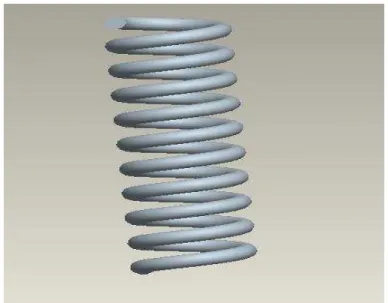
Figure 1. Helical Coil Spring
A helical coil spring is used with the required dimensions as calculated. It is the main part that helps in suspension. It performs the expansion and compression action and provides comfort to the occupants of the car.
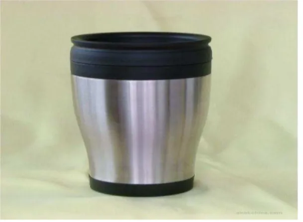
2. STAINLESS STEEL CUP
Figure 2. Stainless Steel Cup
52 3. METAL BUSH
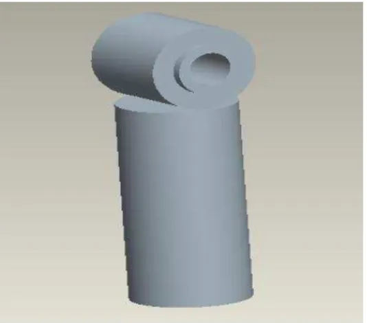
Figure 3. Metal Bush
Metal bush is welded to the ends of the suspension in order to facilitate the attachment of the suspension system to the vehicle. Arc welding is used for the welding.
4. RUBBER PADS
Figure 4. Rubber Pads
Rubber pads are attached in between the moving parts in order to provide better suspension and also to reduce the force on other parts. The rubber pads increase the life of cup sand suspension system.
8. DESIGN CALCULATION 8.1 DESIGN OF SPRING
There are many different types of springs and spring materials. In the design calculations, the following assumptions are considered:
1. The type and form of the spring will be the compression spring ground.
2. The material must be chosen for the maximum energy and mass, such as the spring steel, Chromium Vanadium or Chromium Silicon steel wire.
3. The ends of the spring are to be closed and ground.
4. The spring is to have maximum energy for the limited space, while the stress level is not to exceed the maximum yield strength of the wire.
5. The spring operates periodically with a long interval of rest.
The force Fs produced by a linear elastic spring along its length x with a constant Ks
Fs = Ksx where x – space available when the spring is compressed.
Ks -Spring constant or trial rate, which is a measure of the spring‘s stiffness. It can be determined by:
Ks =G d4 /8ND3
Where G-modulus of elasticity (according to the material and wire diameter) d - wire diameter
D - mean coil diameter N - number of active coils
53
TC- total coils that the spring can contain, which is the ratio between the length of the spring and the diameter of the wire
TC = x/d
In the case that the spring works within a tube or cylinder, the spring outside diameter D must be less in diameter to keep the spring from jamming tin the bore when it is compressed.
The trial mean diameter D0 is equal to the outer diameter minus the wire diameter
D = D0– d The spring index,
C = D / d
And C must be kept in the range between 4 & 14.when the spring index is too low, stress problems occur, and when the index is too high, entanglement and waste of material occur.
The working stress S is calculated using the appropriate equation with the working load F applied to the spring
S = 8 KaD F / π d3 Where the Wahl stress correction factor applied for round wire is
Ka = (4C – 1 / 4C - 4) + 0.615C
If the working stress of the spring is below the maximum allowable stress, the spring is properly designed in relation to its stress level duration operation. The potential energy E that can be stored in a deflected compression spring is given by the constant spring and by the distance that the spring is compressed.
E = K X2 / 2
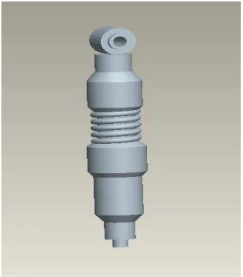
Figure 5. CUP SAND SUSPENSION ASSEMBLY
8.2 NUMERICAL CALCULATIONS FOR SPRING Considering the force produced by the spring Fs = 1000 N Maximum displacement, the spring constant Ks = 16.3 x 10³ N/m. Hence the maximum deflection is x= 0.06135 m
The maximum wire diameter, d = 0.006 m Thus, total coils TC= x / d =10.225 ~ 11 coils.
So that the number of coils that the spring can contain TC = 11 coils.
To keep from jamming the spring, selected are 10 coils, and if the ends are to be closed and ground, the number of active coils N = 8 coils.
The spring outside diameter, D0 = 0.06 m
If the diameter of wire is 0.006 m, the trial mean diameter, D0– d = 0.054 m.
This produces a spring index of C = 9 which is close to the dial index, which must be between 4 & 16.Having the spring constant Ks, the modulus of torsion G = 78.6 x 10⁵ N/m2 for spring steel.
Wahl stress correction factor applied, Ka = 1.16. The stress, S = 738 x 105 N/m2.
54 8.3 DESIGN OF THE CUP
The cup dimensions are chosen according to the dimensions of the spring. As spring outer diameter is 60 mm, we have chosen the below mentioned dimensions for the cup, so that it supplements the springs in suspension. Cup length is chosen so as to reduce bending and also to provide good support.
Cup outer diameter = 63 mm Cup inner diameter = 68 mm Cup material = stainless steel Cup length =100m
Figure 6. Stainless Steel Cup
9. TESTING OF THE CUP SAND SUSPENSION SYSTEM
The load testing of the cup sand suspension system is done by the following methods. 1. The first method is applying a static load and finding the deflection taking place.
2. Then fitting the suspension on the wheels and testing on the road conditions. The suspension is tested in the universal testing machine and the compression is found out is done.
10. ANALYSIS OF CUP SAND SUSPENSION
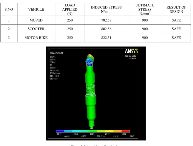
A structural analysis using ansys is carried out on Cup Sand Suspension system. At first a static load of 200N is applied on the suspension and checked for deformation. This load is taken as 200 N considering the weight of two persons of 80 kg each sitting in the vehicle, weight of seat and other parts above suspension. Next, the suspension was tested under various load conditions by fitting it in moped, scooter and motor bike. In all the 3 cases, the design was found to be safe (as the working stress was less than the ultimate stress).
The ultimate stress of the material was found out to be 900 N/mm2 from PSG Design Data book. At first, the suspension was tested with a sample load of 250 N. The image showing the induced stresses in a suspension fixed in the moped is shown in the figure. The data obtained when all the three vehicles (moped, scooter and motor bike) were tested under a load of 250 N is tabulated as follows.
55
TABLE 1: TABLE SHOWING THE STRESS INDUCED IN DIFFERENT VEHICLE
S.NO VEHICLE
LOAD APPLIED
(N)
INDUCED STRESS N/mm2
ULTIMATE STRESS
N/mm2
RESULT OF DESIGN
1 MOPED 250 782.58 900 SAFE
2 SCOOTER 250 802.56 900 SAFE
3 MOTOR BIKE 250 822.51 900 SAFE
Figure 7. Induced Stress Distribution
11. ADVANTAGES OF THE CUP SAND SUSPENSION SYSTEM
1) Possibility of leakage is comparatively less as sand is used as the damper medium as to oil and gas used in other suspension systems.
2) Failure due to the sudden application of load is avoided (Buckling). 3) Both compression and expansion of springs takes place.
4) Manufacturing cost is less and maintenance cost is less. 5) Sand is readily and easily available.
12. DISADVANTAGES OF THE CUP SAND SUSPENSION SYSTEM 1. Frequent replacement of the sand.
2. Abrasive friction of the sand.
3. Suspension may bend due to increased length.
13. CONCLUSION
56 14. REFERENCES
[1]. Machine elements-design and calculation for mechanical engineers, by GUSTAV NEIMANN, Edition 1976. [2]. Design Data Book, PSG College of Technology, Coimbatore.
[3]. S.M. Cormie, T.A. Stolarski
,
The influence of friction in the guide bearing on the damping characteristic of a suspension system‖, Original Research Article Tribology International, Volume 19, Issue 6, December 1986, Pages 318-323.[4]. R.BenMrad, J.A. Levitt, S.D. Fassois Non-linear dynamic modeling of an automobile hydraulic active suspension system , Original Research Article Mechanical Systems and Signal Processing, Volume 8, Issue 5, September 1994, Pages 485-517.
[5]. T.J. Gordon ―Non-linear optimal control of a semi-active vehicle suspension system‖, Chaos, Solitons & Fractals, Volume 5, Issue 9,1995, Pages 1603-1617.
[6]. R. Ben Mrad, S.D. Fassois, J.A. Levitt, B.I. Bachrach
,
On-Board Prediction of Power Consumption in Automobile Active Suspension Systems—I: Predictor Design Issues,
Original Research Article Mechanical Systems and Signal Processing, Volume 10, Issue 2, March 1996, Pages 135-154.[7]. D. Hrovat ―Survey of Advanced Suspension Developments and Related Optimal Control Applications‖, Automatica, Volume 33, Issue 10, 1997, Pages 1781-1817.
[8]. R Ben Mrad, S.D Fassois, J.A Levitt
,
A polynomial-algebraic method for non-stationary TARMA signal analysis – Part II: Application to modeling and prediction of power consumption in automobile active suspension systems,
Original Research Article Signal Processing, Volume 65, Issue 1, 27 February 1998, Pages 21-38.[9]. H.A. Al-Qureshi
,
Automobile leaf springs from composite materials,
Original Research Article Journal of Materials Processing Technology, Volume 118, Issues 1–3, 3 December 2001, Pages 58-61. [10]. Simionescu and D. Beale,―Synthesis and analysis of the five-link rear suspension system used inautomobiles
,
Original Research Article, Mechanism and Machine Theory, Volume 37, Issue 9, September 2002, Pages 815-832.[11]. J.J. Fuentes, H.J. Aguilar, J.A. Rodríguez, E.J. Herrera