Abstract
This research paper is concerned with the disc brake squeal problem for passenger cars. The aim of the present research is developing a finite element model of the disc brake as-sembly in order to improve understanding of the influence of Young’s modulus on squeal generation. A detailed finite element model of the whole disc brake assembly that inte-grates the wheel hub and steering knuckle is eveloped and validated using experimental modal analysis. Stability analysis of the disc brake assembly is accomplished to find unstable frequencies. A parametric study is carried to look into the effect of changing Young’s modulus of each brake components on squeal generation. The results of simulation indicated that Young’s modulus of disc brake components play a substantial role in generating the squeal noise.
Keywords
Disc brake squeal; finite element analysis; Young’s modulus; steering knuckle.
Effects of material properties on generation of brake squeal noise
using finite element method
1 INTRODUCTION
Passenger cars have been one of the essential ground transportation for people to move from one place to another. The braking system acts as one of the most fundamental safety-critical compo-nents in modern passenger cars. Therefore, the braking system of a vehicle is a significant system, especially in slowing down or stopping the vehicle. Due to the braking operation, the brake sys-tem generates an unwanted high frequency sound called squeal noise. It occurs in the frequency range between 1 and 16 kHz and leads to customer dissatisfaction and increases warranty costs. Although substantial research has been conducted into predicting and eliminating brake squeal since the 1930s, it is still rather difficult to predict its occurrence (Papinniemi et al., 2002). As described in some of the recent review papers (Kinkaid et al., 2003; Ghazaly et al., 2014; Cantoni et al., 2009; Ouyang et al., 2005), theories on brake squeal mechanisms have been put forward on six major classes, namely, stick–slip, sprag–slip, negative friction velocity slope, hammering
exci-Ali Belhocinea
Nouby Mahdi Ghazalyb
aDepartment of Mechanical Engineering,
USTO Oran University, B.P 1505 El - Mnaouer, USTO 31000, Oran, Algeria
bDepartment of Mechanical Engineering.
tation, splitting the doublet modes and mode coupling of structures. These mechanisms are essen-tial for better understanding of squeal noise.
In recent years, the finite element (FE) method has become the preferred method in studying brake squeal. The capabilities of FE models, with a huge number of degrees of freedom, have enabled the accurate representation of the brake system. The analysis of disc brake squeal using FE model can reflect each detail of the brake design, while this demands a lot of effort to do sig-nificant changes in the geometry of components (Joe et al., 2008). Due to a general lack of confi-dence in FE models, the dynamic testing of structures has become a standard procedure for model validation and updating. Over the past years, modal testing and analysis have become a fast-developing technique for the experimental evaluation of the dynamic properties of structures (Ewins, 2001). Several types of analyses have been performed on disc brake systems through FEA, in an attempt to understand the problem of noise and develop a predictive design tool. There are two numerical methods that are used to study this problem namely; transient dynamic analysis (Nouby et al., 2011; Hu et al., 1999) and complex eigenvalue analysis (Kung et al., 2000; Abdo et al., 2010; Liu et al., 2007; Abu-Bakar and Ouyang, 2008). Currently, the complex eigen-value method is the most commonly and preferred method. Generally, the existence of complex eigenvalues with positive real parts indicates the presence of instability and the magnitude of the real part is used to represent the level of system instability or squeal propensity.
Reduction and elimination the brake squeal is an important task for the improvement of vehi-cle passengers' comfort. Many researchers in their studies on the brake system tried to reduce squeal noise through changing the factors associated with the brake squeal. For example Liles (1989) found that shorter pads, damping, softer disc and stiffer back plate could reduce squeal whilst in contrast, higher friction coefficient and wear of the friction material were prone to squeal. Lee et al. (1998) reported that reducing back plate thickness led to less uniform of contact pressure distributions and consequently increasing the squeal propensity. Kung et al. (2000) in their simulations showed that instability of the disc brake was dependent upon a range of disc Young’s modulus. Liu et al. (2007) commented that the squeal can be reduced by decreasing the friction coefficient, increasing the stiffness of the disc, using damping material on the back of the pads and modifying the shape of the brake pads. Recently, Nouby et al. (2009) introduced a com-bined approach of complex engenvalue analysis (CEA) and design of experiments to get optimal design for the brake system. They reported that the brake squeal propensity can be reduced by increasing Young’s modulus of the back plate and modifying the shape of friction material by adding chamfer and slots.
In FEA, several researchers vary the geometric details of the brake assembly model. For ins-tance, some researchers (Liu et al., 2007; Trichês Junior et al., 2008) considered only the disc brake and two pads. Hassan et al. (2009) added the finger and piston to the FE model. Dai and Teik (2008) developed a FE model consists of rotor, caliper, mounting bracket, piston and brake pads to analyze the design of disc brake pad structure for squeal noise reduction. Some authors (Abu-Bakar, 2005; Papinniemi, 2007; Lou et al., 2004) used more detailed FE model which con-sists of a disc, a piston, a caliper, a carrier, piston and finger pads, two bolts and two guide pins. An extension of the FE models discussed earlier, in this work a 3-dimensional of a validated FE model of the disc brake assembly that incorporates the wheel hub and steering knuckle is considered. Experimental modal analysis of a disc brake system is first used to develop and
date the FE model to improve accuracy of simulation results. Then, stability of the disc brake assembly with frequencies ranging from 1 kHz to 10 kHz is examined, using FE software ABA-QUS. A preliminary FE simulation is carried out to predict unstable frequencies by applying complex eigenvalue analysis to the FE model. Finally, the parametric study as a guide is conduc-ted to evaluate the influence of the Young’s modulus of the disc brake components.
2 FINITE ELEMENT MODEL
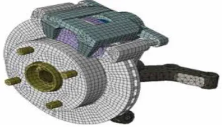
A detailed three dimensional finite element (FE) model of a vented disc brake assembly that has been used in this work is shown in Figure 1. All disc brake system components, except a rubber seal (attached to the piston), two rubber washers (attached to the guide pins) and pad insulator, have been included in the model. The FE model consists of a disc, a piston, a caliper, an anchor bracket, a wheel hub, a steering knuckle, piston and finger pads, two bolts and two guide pins. All the disc brake components are modeled in order to achieve as accurate a representation as possible of a real disc brake.
Figure 1: Finite element model of disc brake assembly.
The FE model uses up to 19,000 solid elements and approximately 78,000 Degrees of Freedom (DOFs). The disc, brake pads, piston, wheel hub, guide pins and bolts are developed using 8-node (C3D8) linear solid elements while other components are developed using a combination of 8-node (C3D8), 6-node (C3D6) and 4-node (C3D4) linear solid elements. Details for each of the compo-nents are given in Table 1.
In the brake assembly FE model, all the disc brake components are integrated together to form an assembly model and all boundary conditions and component interfaces are considered. Contact interaction between disc brake components is represented by a combination of node-to-surface and node-to-surface-to-node-to-surface contact elements. The node-to-surface of the disc is defined as the master surface since it has a coarser mesh than the pad and the disc is a stiffer material. The pad is the-refore treated as the slave surface. This enables the slave surface to potentially contact the entire master surface.
3 VALIDATION OF THE FE MODEL
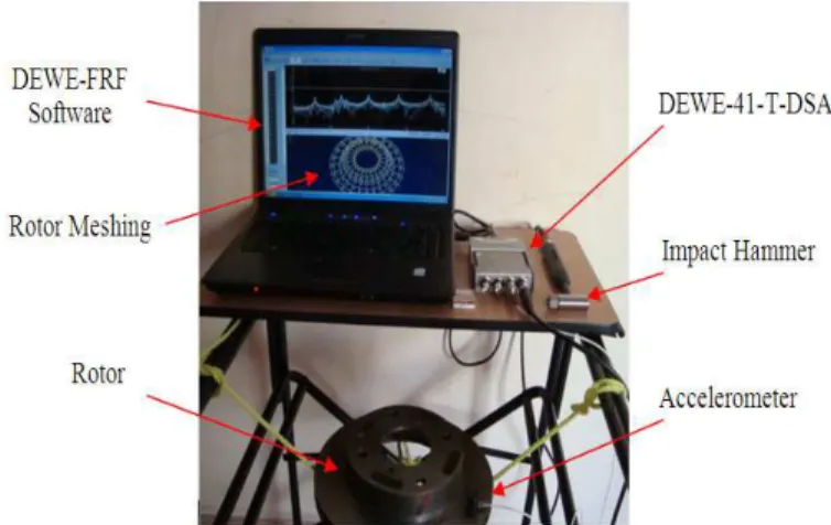
The purpose of this section is to ensure that accuracy of the dynamical properties of the FE mo-del agree with those of the physical component. There are two validation stages are established, i.e., modal analysis at component and assembly levels. Frequency Response Functions (FRF) measurements using impact hammer and accelerometer are recorded by DEWE/FRF software. Fig. 2 shows the experimental modal analysis set-up.
Disc brake Components Types of Element No. of Elements No. of Nodes
Disc C3D8 2559 4988
Friction Material C3D8 320 558
Back plate C3D8 233 526
Caliper
C3D8 C3D6 C3D4
2334 2370
Anchor Bracket C3D8
C3D4 1036 1644
Steering Knuckle
C3D8 C3D6 C3D4
9868 3585
Wheel Hub C3D8 1654 2786
Piston C3D8 357 576
Guide pin C3D8 292 414
Bolt C3D8 58 123
Table 1: Element details of disc brake components.
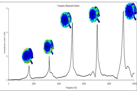
First, modal analysis at the component level is carried up to frequencies of 10 kHz. The FRF result for brake rotor is performed at free-free boundary conditions, as shown in Fig. 3. An accu-rate representation of the component model forms one of the validation stages for good squeal correspondence between experiments and predictions. In order to correct the predicted frequencies with the experimental results an FE updating is used to reduce relative errors between the two sets of results by tuning material. The baseline material properties of the disc brake components after FE updating are listed in Table 2. It is found that the predicted natural frequencies for bra-ke rotor is quite close to those obtained in the measured data as listed in Table 3. In a similar way, validation of the other brake components is performed. It is also found that a good agree-ment between the predicted results and the measured data for the brake components, as listed in Appendix A.
Figure 2: Experimental modal analysis set-up.47.
Figure 3: FRF measured for the brake rotor.
Components Density (kg/m3) Young’s Modulus (GPa) Poisson’s ratio
Disc 7155 125 0.23
Friction material 2045 2.6 0.34
Back plate 7850 210 0.30
Caliper 7005 171 0.27
Anchor Bracket 7050 166 0.27
Steering Knuckle 7625 167 0.29
Wheel Hub 7390 168 0.29
Piston 8018 193 0.27
Guide pin 2850 71 0.30
Bolt 7860 210 0.30
Table 2: Material properties of disc brake component.
Mode 1 2 3 4 5
Exp. (Hz) 1464 3198 4992 6957 9020
FEA (Hz) 1453 3225 5062 7067 9170
Error (%) -0.7 0.8 1.4 1.5 1.6
Table 3: Comparisons between the predicted results and measured data for brake rotor.
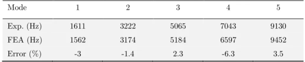
The second validation stage is to perform dynamic characteristics of the complete assembly with boundary conditions. In the experimental modal analysis, the individual components are fixed on a brake test rig under applied pressure of 1 MPa, as shown in Fig. 4. The results of the FRF measured for disc brake assembly was plotted in Fig. 5. A similar condition is also applied to the FE brake assembly model. In this validation, measurements are taken on the disc as it has a re-gular shape than the other components. From the analysis results, it is shown that a good agree-ment is found between the predicted results and the measured data, as shown in Table 4.
Figure 4: Experimental modal analysis of brake assembly.
Mode 1 2 3 4 5
Exp. (Hz) 1611 3222 5065 7043 9130
FEA (Hz) 1562 3174 5184 6597 9452
Error (%) -3 -1.4 2.3 -6.3 3.5
Table 4: Comparisons between the predicted results and measured data for brake assembly.
4 CONTACT ANALYSIS
In recent years, the complex eigenvalue analysis has become a preferred method to investigate the stability of brake system modes. Complex eigenvalues usually result from the frictional coupling of brake components due to the off-diagonal terms that arise in the stiffness matrix of the system causing it to be unsymmetrical. The positive real parts of the complex eigenvalues indicate the degree of instability of the disc brake assembly and reflect the likelihood of squeal occurrence. Complex eigenvalues with positive real parts are identified as unstable modes and corresponding frequencies, which always appear in complex conjugate pairs. The complex eigenvalue analysis in ABAQUS is utilised to determine instability of the disc brake assembly (Liles, 1989). In order to perform the complex eigenvalue analysis using ABAQUS, four main steps are required. They are given as follows:
• Nonlinear static analysis for applying brake-line pressure. • Nonlinear static analysis to impose rotational speed on the disc.
• Normal mode analysis to extract natural frequency of undamped system. • Complex eigenvalue analysis that incorporates the effect of friction coupling.
The complex eigenvalue analysis is examined between 1 kHz and 10 kHz using ABAQUS ver-sion 6.8 with brake-line pressure of 0.7 MPa, a rotational speed of 5 rad/s (5.5 km/h) to assess the brake propensity as the friction coefficient values. The influence of friction coefficient of the pad-rotor interface is performed. The unstable modes for varying μ from 0.1 to 0.5 are plotted as real parts versus frequency in Fig. 5 to illustrate how the instability increases with friction level. It is found that the propensity for squeal increases with higher coefficients of friction. This is be-cause the higher coefficient of friction be-causes the variable frictional forces to be higher resulting in the tendency to excite greater number of unstable modes.
In this study, the baseline model for investigating the effects of elastic modulus of the main disc brake components on squeal generation is considered at 0.5, applied pressure of 0.7 MPa and a rotational speed of 5 rad/s (5.5 km/h). Fig. 6 shows the contact pressure distribution bet-ween the brake pads (finger pad and piston pad) and the disc brake. It is found that at 0.5 there are five unstable frequencies predicted at 2777 Hz, 7573 Hz, 8530 Hz, 9453 Hz and 9722 Hz, as shown in Fig. 7.
5 PARAMETRIC STUDIES
The aim of this section is to propose parametric studies in order to examine the effects of mate-rial properties of the disc brake components on disc brake squeal generation. Fieldhouse and Steel
(a) Finger brake pad (b)Piston brake pad
Figure 6: Contact pressure distribution of the brake pads on the brake disc.
Figure 7: Predicted unstable frequencies for varying coefficient of friction values.
(2003) suggested that the source of a noisy brake may lie as much in basic mechanical design as inappropriate material choice. When the components are in an assembly, there may be a signifi-cant redistribution of stiffness and mass throughout the structure if a component’s material pro-perty is changed. This in turn will change the natural frequencies of the assembly as a whole as well as potentially varying the strain energy distribution during vibration. As a consequence, it is necessary to design the entire brake components such that their natural frequencies in the audible range are as isolated as possible to avoid mode coupling. In this study, the effect of elastic mo-dulus for disc brake components is examined using parametric studies in order to reduce squeal generation. Theoretically, this is thought to have been achieved when either the positive real parts of eigenvalues of the baseline model are reduced or the predicted unstable frequencies in the baseline model totally disappeared. Details of the parametric study of Young’s modulus of the disc brake components will be discussed below.
5.1 Influence of rotor Young’s modulus
Disc brake rotors in wide use today are made of gray cast irons, because they have acceptable thermal properties, sufficient mechanical strength, satisfactory wear resistance, good damping properties, it is cheap, and it is also relatively easy to cast. Gray cast irons differ somewhat to steels and most other structural metals in that the Young’s modulus can be varied significantly by changing carbon equivalent. This allows rotors to be manufactured with Young’s modulus that runs from below 100 GPa through to approximately 140 GPa.
In this section, variation of Young’s modulus of the brake rotor from 100 GPa to 140 GPa is simulated. Where the baseline Young’s modulus of the disc is 125 GPa. The density and Poisson’s ratio of these variants is assumed to be as the same as the baseline model. Fig. 8 presents the real parts versus frequency for different Young’s modulus of the rotor. From the simulation results, it is found that increasing Young’s modulus of the rotor to 140 GPa is capable of eliminating positi-ve real parts for unstable frequencies of 2777 Hz, 8530 Hz and 9722 Hz. On the other hand, redu-cing Young’s modulus of the rotor to 100 GPa, a new unstable frequency has appeared at appro-ximately 5100 Hz. In addition to, the number of unstable frequencies is unchanged but their magnitudes are increased especially at frequencies of 2777 Hz, 7573 Hz, 9453 Hz and 9722 Hz. It is thought, in theory, that the higher positive real parts the more tendency the squeal to occur. Overall, it is observed that the rotor Young’s modulus has a significant effect on the stability of the system. Increasing Young’s modulus of the disc may be reducing the brake squeal generation. Similar evaluations have been carried out in reference (Liu et al., 2007). Also, Dunlap et al. (1999) reported that increased rotor stiffness is directionally correct for reduction in squeal pro-pensity.
Figure 8: Effect of the Young’s modulus of the rotor on the brake squeal generation.
5.2 Influence of friction material Young’s modulus
Friction-induced vibration due to mode coupling is a major concern in a wide variety of mechani-cal systems. Though there are numerous papers on both linear and non-linear stability analyses of dynamical systems with friction-induced vibrations, the effects of damping on the evolution of the stable–unstable regions is not yet fully understood (Abu Bakar, 2005). Lightweight structures
typically have low inherent structural damping. Effective vibration suppression is required, for example, in certain applications involving precision positioning (Sinou and Jezequel, 2008).
It is necessary to investigate the effect of the friction material stiffness on the squeal propensi-ty for the design of a quiet brake system, since changes in the pad stiffness can alter the mode coupling between the pads and rotor. In this section, variation of Young’s modulus of the friction material from 0.5 GPa to 4 GPa is simulated. These values of Young’s modulus are in the range readily attained within brake pads available in the market (Lee et al., 2003). Where the baseline Young’s modulus of the disc is 2.6 GPa. The other properties such as Poisson’s ratio and density of these variants is assumed to be as the same as the baseline model. Similarly, Young’s modulus of other components is also unchanged. Having simulated the variation of Young’s modulus of the friction material, it can be seen from Fig. 9 that increasing Young’s modulus of the friction mate-rial to 4 GPa is capable of eliminating positive real parts for unstable frequencies of 7573 Hz, 8530 Hz and 9722 Hz, in addition reducing the positive real part for unstable frequency of 9453 Hz. On the other hand, reducing Young’s modulus of the friction material to 0.5 GPa increasing the overall number of unstable frequencies and the real parts especially at high frequency squeal.
Figure 9: Effect of the Young’s modulus of the friction material on the brake squeal generation.
From the predicted results, it can be concluded that stiffer friction material causes the system to be more stable and reduces squeal generation. This finding seems to agree with that from referen-ce (Liles, 1989). Also, Papinniemi (2007) reported that increasing pad Young’s modulus redureferen-ces the overall number of unstable modes and indicates that overall system stability would be enhan-ced with higher modulus pads. The most probably physical explanation for this would be reduc-tion in pad deformareduc-tion.
5.3 Influence of anchor bracket Young’s modulus
The anchor bracket is made of ductile cast iron component used for housing the caliper and pads in the brake assembly. This anchor bracket is attached to the steering knuckle. The baseline Young’s modulus of the bracket is 166 GPa. In this section, the baseline Young’s modulus of the bracket is varied approximately up to ±10%. The other properties such as Poisson’s ratio and
density are kept constant throughout the parametric study. Similarly, Young’s modulus of other components is also unchanged. From the complex eigenvalue analysis, it is seen that the anchor bracket has a significant affect on the stability of the system. From Fig. 10, increasing the mo-dulus to 180 GPa reducing the number of unstable modes to just 3. On the other hand, reducing the Young’s modulus to 150 GPa had less of an impact with unstable frequencies still present at 2777 Hz, 8530 Hz, 9453 Hz and 9722 Hz. In addition, a new unstable frequencies have appeared in frequencies of 3403 Hz, 5873 Hz and 9530 Hz. Dessouki et al. (2003) concluded that the common countermeasure for caliper bracket induced squeal was to introduce mass loading to the caliper bracket or alternatively to stiffen the bracket. This finding seems to agree with current simulation results, which is observed that increasing Young’s modulus of the anchor bracket may be redu-cing the brake squeal generation.
Figure 10: Effect of the Young’s modulus of the bracket on the brake squeal generation.
5.4 Influence of back plate Young’s modulus
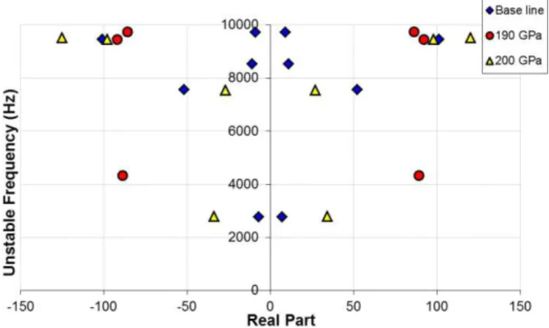
The disc brake pads consist of two parts, friction plates which are made of organic material and back plates made of steel. In this study, the baseline Young’s modulus of the back plates of the pads is 210 GPa. Steel does not show much variation in modulus, but an alternative case is run with the back plates modulus set to 190 GPa and 200 GPa. From Fig. 11, it is seen that reducing Young’s modulus of the back plate to 190 GPa is capable of eliminating positive real parts for unstable frequencies of 2777 Hz, 7573 Hz and 8530 Hz. However, a new unstable mode appears at approximately 4330 Hz, so the overall noise performance of the system may be significantly im-proved by reducing the number of unstable frequencies to just 3. On the other hand, reducing Young’s modulus of the back plate to 200 GPa had less of an impact with unstable frequencies still present at 2777 Hz, 7573 Hz, 9453 Hz and 9722 Hz. However, the unstable frequency of 8530 Hz is eliminated. Compared to the baseline case, setting back plates modulus to 200 GPa reduced the number of unstable frequencies to just 4.
From simulation results, it is observed that the stiffer back plates cause a higher squeal pro-pensity. This is so since the friction material connected to the back plates is very soft compared with the back plate material. Hence the higher stiffness of the back plates, the greater the uneven deformation and vibration magnitude of the pad, and hence the higher the damping coefficient.
Figure 11: Effect of the Young’s modulus of the back plate on the brake squeal generation.
5.5 Influence of caliper Young’s modulus
The base line Young’s modulus of the caliper is 171 GPa. In this section, the baseline Young’s modulus of the caliper is varied approximately up to ± 10%. The other properties such as Pois-son’s ratio and density are kept constant throughout the parametric study. Similarly, Young’s modulus of other components is also unchanged. Having simulated the variation of Young’s mo-dulus of the caliper, it can be seen from Fig. 12 that the caliper also has a significant affect on the stability of the system. Reducing the modulus to 155 GPa reduced the number of unstable modes to just 3. On the other hand, increasing Young’s modulus of the caliper to 190 GPa is capable of suppressing positive real parts for unstable frequencies of 2777 Hz, 7573 Hz and 9722 Hz. Compa-red to the baseline case, setting the caliper modulus to 190 GPa Compa-reduced the number of unstable frequencies to just 2.
Figure 12: Effect of the Young’s modulus of the caliper on the brake squeal generation.
Liles (1989) in his simulations suggested that varying the caliper Young’s modulus did not much affect instability of the disc brake model. Also, Papinniemi (2007) reported that caliper stiffness may not be beneficial for overall system stability. However, in this study, the results show that varying caliper Young’s modulus has somewhat effect on the number of unstable frequencies. By
varying this value, it seems that the unstable frequencies are varied from one to another even though some of them remain.
5.6 Influence of steering knuckle Young’s modulus
The base line Young’s modulus of the steering knuckle is 167 GPa. In this section, the baseline Young’s modulus of the steering knuckle is varied approximately up to ± 10%. The other proper-ties such as Poisson’s ratio and density are kept constant throughout the parametric study. Simi-larly, Young’s modulus of other components is also unchanged. Results in Fig. 13, shows real and imaginary parts of the complex eigenvalues when Young’s modulus of the friction material varies from 150 GPa to 180 GPa. It is found that the number of unstable frequencies is unchanged for varying Young’s modulus of the steering knuckle but their magnitudes vary nonlinearly. It is also observed that at frequencies 2777 Hz and 7573 Hz, increasing Young’s modulus of the steering knuckle lead to reduce the real values. However, at frequencies 8530 Hz, 9453 Hz and 9722 Hz the real parts vary nonlinearly. It can be concluded that Young’s modulus of the steering knuckle may not be beneficial for overall system stability.
Figure 13: Effect of the Young’s modulus of the steering knuckle on the brake squeal generation.
5.7 Influence of wheel hub Young’s modulus
The base line Young’s modulus of the wheel hub is 168 GPa. In this section, the baseline Young’s modulus of the wheel hub is varied approximately up to ± 10%. The other properties such as Poisson’s ratio and density are kept constant throughout the parametric study. Similarly, Young’s modulus of other components is also unchanged. From the complex eigenvalue analysis, it is found that there are unstable frequencies that increasing Young’s modulus of the wheel hub to 190 GPa is capable of eliminating positive real parts for unstable frequencies of 2777 Hz and 8530 Hz. However, a new unstable mode appears at approximately 5800 Hz. From Fig. 14, setting wheel hub modulus to 190 GPa reduced the number of unstable frequencies to just 4. On the other hand, reducing Young’s modulus of the wheel hub to 155 GPa had less of an impact with unstable frequencies still present at 7573 Hz, 9453 Hz and 9722 Hz. However, the unstable fre-quencies of 2777 Hz and 8530 Hz are eliminated. Compared to the baseline case, setting wheel hub modulus to 155 GPa reduced the number of unstable frequencies to just 3. The results from the simulations indicate a range of instability in terms of the wheel hub Young’s modulus.
Figure 14: Effect of the Young’s modulus of the wheel hub on the brake squeal generation.
6 CONCLUSIONS
This study has investigated the effect of Young’s modulus variations of the disc brake compo-nents on the squeal propensity using a detailed three dimensional finite element model. Prior to the stability analysis using complex eigenvalue analysis, reasonably good agreement is achieved between predicted and experimental results in terms of dynamic characteristics of the developed FE model. The simulation result showed that instability of the disc brake is sensitive to Young’s modulus variations of the disc brake components. It is worth noting that some of those variations reduce the number of unstable frequencies and consequently provide better squeal performance. Especially, increasing Young’s modulus of the rotor, friction material, anchor bracket and back plate. On the other hand, the variations of Young’s modulus of the caliper and wheel hub have somewhat effect on the squeal generation. It is also observed that the variation of Young’s mo-dulus of the steering knuckle has little influence on the brake to alter its tendency to generate squeal noise.
Acknowledgements
The authors would like to thank Mr. Govardhana Giri of ATALON Testing and Consulting En-gineers for his help in conducting modal testing experiments.
References
Abdo, J., Nouby, M., Mathivanan, D., Srinivasan, K., (2010). Reducing disc brake squeal through FEM approach and experimental design technique. Int. J. Veh. Noise and Vib. 6(2/3/4): 230–246.
Abu-Bakar, A.R., (2005). Modelling and simulation of disc brake contact analysis and squeal. PhD thesis, De-partment of Engineering, University of Liverpool.
Abu-Bakar, A.R., Ouyang, H., (2008). A prediction methodology of disc brake squeal using complex eigenvalue analysis, Int. J. Vehicle Design 46: 416–435.
Cantoni, C., Cesarini, R., Mastinu, G., Rocca, G., Sicigliano, R., (2009). Brake comfort – a review. Vehicle Sys-tem Dyn 47: 901–947.
Dai, Y., Teik, C.L., (2008). Suppression of brake squeal noise applying finite element brake and pad model enhan-ced by spectral-based assurance criteria. Appl. Acoust. 69: 196–214.
Dessouki, O., Brake, G., Lowe, B., Chang, W.K., (2003). Disc brake squeal: diagnosis and prevention. SAE Paper 2003-01-1618.
Dunlap, K.B., Riehle, M.A., Longhouse, R.E, (1999). An investigation overview of automotive disc brake noise. SAE Paper 1999-01-0142.
Ewins, D.J., (2001). Modal testing: theory and practice. Research Studies Press.
Fieldhouse, J.D., Steel, W.P., (2003). A study of brake noise and the influence of the centre of pressure at the disc/pad interface, the coefficient of friction and caliper mounting geometry. Proc. IMechE Part D. 217: 957–973. Ghazaly, N.M., El-Sharkawy, M., Ahmed, I., (2014). A review of automotive brake squeal mechanisms. J. Mech. Des. Vib. 1(1): 5-9.
Hassan, M.Z., Brooks, P.C., Barton, D.C., (2009). A predictive tool to evaluate disk brake squeal using a fully coupled thermo-mechanical finite element model. Int. J. Vehicle Design 51: 124-142.
Hu, Y., Mahajan, S., Zhang, K., (1999). Brake squeal DOE using nonlinear transient analysis. SAE Paper 1999-01-1737.
Joe, Y.G., Cha, B.G., Sim, H.J., Lee, H.J., Oh, J.E., (2008). Analysis of disc brake instability due to friction-induced vibration using a distributed parameter model. Int. J. Auto. Tech. 9: 161-171.
Kinkaid, N.M., O’Reilly, O.M., Papadopoulos, P., (2003). Automotive disc brake squeal. J. Sound Vib. 267: 105– 166.
Kung, S.W., Dunlap, K.B., Ballinger, R.S., (2000). Complex eigenvalue analysis for reducing low frequency brake squeal. SAE 2000-01-0444.
Lee, Y.S., Brooks, P.C., Barton, D.C., Crolla, D.A., (1998). A study of disc brake squeal propensity using a para-metric finite element model. In IMechE Conference Transaction, European Conference on Noise and Vib. 191–201. Lee, Y.S., Brooks, P.C., Barton, D.C., Crolla, D.A., (2003). A predictive tool to evaluate disc brake squeal pro-pensity part 3: parametric design study. Int. J. Vehicle Design 31: 330-353.
Liles, G.D., (1989). Analysis of disc brake squeal using finite element methods. SAE 891150.
Liu, P., Zheng, H., Cai, C., Wang, Y.Y., Lu, C., Ang, K.H., Liu, G.R., (2007). Analysis of disc brake squeal using the complex eigenvalue method. Appl. Acoust. 68: 603–615.
Lou, .G., Wu, T.W., Bai, Z., (2004). Disk brake squeal prediction using the ABLE algorithm. J. Sound Vib. 272: 731–748.
Nouby, M., Mathivanan, D., Srinivasan, K., (2009). A combined approach of complex eigenvalue analysis and design of experiments (DOE) to study disc brake squeal. Int. J. Eng, Sci. Tech. 1: 254-271.
Nouby, M., Sujatha, C., Srinivasan, K., (2011). Modelling of automotive disc brake squeal and its reduction using rotor design modifications. Int. J. Veh. Noise Vib. 7(2): 129 – 148.
Ouyang, H., Nack, W.V., Yuan, Y., Chen, F., (2005). Numerical analysis of automotive disc brake squeal: a re-view. Int. J. Veh. Noise Vib. 1: 207-230.
Papinniemi, A., (2007). Vibro–Acoustic Studies of Brake Squeal, PhD Thesis, The University of New South Wales.
Papinniemi, A., Lai, J.C.S., Zhao, J., Loader, L., (2002). Brake squeal: a literature review. Appl. Acoust. 63: 391– 400.
Sinou, J.J., Jezequel, L., (2008). On the stabilizing and destabilizing effects of damping in a non-conservative pin-disc system. Acta Mechanica 199(Issue 1-4): 43-52.
Trichês Junior, M., Samir, N.Y., Jordan, R., (2008). Analysis of brake squeal noise using the finite element met-hod: A parametric study. Appl. Acoust. 69: 147–162.
Appendix A: Comparisons between the predicted results and measured data for brake compo-nents.
Components Mode Exp. (Hz) FE (Hz) Error (%) Mode shape
Anchor bracket
1 878 880 0.2
2 1770 1755 -0.8
3 3341 3164 -5.2
Caliper
1 2282 2293 -1.7
2 3769 3960 5
3 5017 5182 3.2
Brake pad
1 2819 2889 2.4
2 7067 6735 -4.6
Piston 1 7287 7392 1.4
Steering knuckle and Wheel hub
1 1232 1211 -1.7
2 2138 2242 4.8
3 4856 4421 8.9