PRODUCAO
Tool Management in Manufacturing Systems
Equipped With CNC Machines
Giovanni Tani
Dipartimento di Meccanica e Tecnologie Industriali - Facolta di Ingegneria Universita di Firenze - Via S. Marta 3 - FIRENZE - ITALIA
Key words: Tool file, Tool Card, Automatic Tool Selection
ABSTRACT
This wolk has been carned out for the purpose of realizing an automated system for the integrated management of tools within a company. By integrating planning, inspection and tool-room functions, automated tool management can ensure optimum utilization of tools on the selected machines, guaranteeing their effective availability.
PRODUCAo
1.
Introduction
While tool management is a particularly urgent need in FMS installations, it is also becoming increasingly important in shops that produce small lots. Efficient planning and control of production necessarily calls for real-time knowledge of the situation of the production system, within which tools have an important role.
In response to market demand, companies now produce highly differentiated products. As a result, manufacturing has become enormously more complicated and increasingly greater resources are needed to stay competitive. One of these resources consists expressly of tools, which have now taken on significant weight also as regards financial aspects. The complexity of the tools, the performance level required and the great number of services demanded make their overall cost a major item in a company's accounts.
Frequently, moreover, the lack of effective standardization of tools leads to their excessive proliferation as well as continuous modifications in the solutions adopted by the programmers of CNC Machine Tools.
For these reasons, specialized software systems for the implementation of tool management procedures (Tool Management System - TMS) have been introduced, starting in the 1980s. The first applications were chiefly concerned with tool management on the shop level; here in fact TMS is utilized for "physical" management of tools, both in the Store Room where tools for current use are usually kept and in the Tool Room, where
tools are taken from the warehouse, prepared for machining, preset, reground or regenerated.
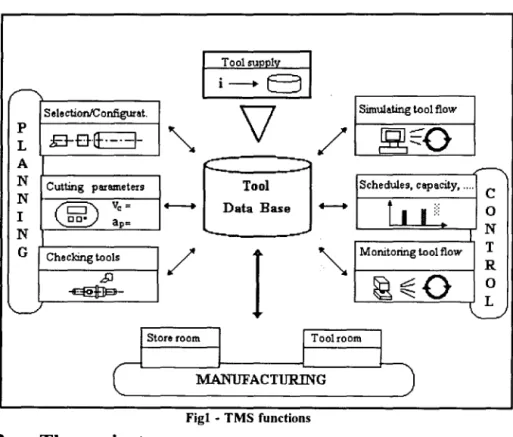
Within the sphere of Production Systems, the development of the concept of integration has subsequently led to considering the integrated management of tools. Data on tools do not concern shop procedures alone, but are absolutely essential for establishing the working cycle of a product and for programming machine tools to carry out the various operations. Some information, moreover, must also be made available to the company's management system.(Fig.l)
The objectives that may be attained through the implementation of an integrated TMS system include:
- improvement in performance of the Production System
- high levels of machine utilization - reduction in downtime
- optimum tool selection
- reduction in variety and number of tools used
- optimized industrial purchasing - supplying tools to machines just in time
involving the engineering department in the concerns of the shop.
I
ゥtセbi@
S ele ctionIC onfigunt.\l
Simulating tool flow pE-B-{f. _.
-1-
セ@
/
セセo@
L
A C セ@
N Cutting parameters Tool Schedules, capacity, ....
C
N
HセI@
Vo = +--+ Data Base--
f
I
j :::
0I ap=
N
N "-
..-T G Checking tools
/
I
セ@
Monitoring tool flow R.,!:)
セセッ@
0セM L
'--'
I
Store roomI
1
Toolroom1
I
I
L
r
MANUFACTURING)
Fig! - TMS functions2.
The project
The objective of the work carried out was that of designing a Tool Management System able to provide management of tools, perfectly integrated with the company departments involved in this activity, more specifically with the Schedules and Methods Department and the Shop Engineering Department, the Tool Store Room and the Tool Room, the Industrial Purchasing and Accounting Departments.
The project, carried out in several stages, first calls for the creation of a Tools
PRODUCAo
Processes
I
MaterialsI
MachinesI
ToolsI
MethodsI
FixtureI
Cutting DataTeclmological Data - Bases
セセ@
I
Manufill:turingI
Enpeerin8
I
WarehouseI I
P r o : m sI I
Tool- RoomI
- Pro cess Planning - Pw:chasing - Defining working - Prep ering c orre ction
cycle, data
- Scheduling - Storing - Def. assemblies - Setting up tools
- Machine, utili:J:won -Coding - Def. cutting data - Tools regeneration
- Sp are parts - Prep. theoretical - Prep. physical tool card tool card
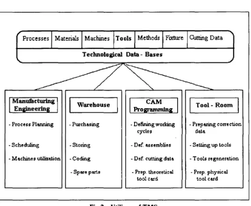
Fig 2 - Utilizers of TMS
The Tool Management System developed, based on this file, can be used to obtain the assemblies of tools and the Tool Card utilized in compiling work cycles, CAM programming and "physical" preparation of tools in the Tool-rooms, ensuring correct rationalization and standardization of tool use. (Fig. 3)
3. The Tool File and the TMS
developed
The structure ofthe data base utilized is the standard DEC RDB (Relational Data Base), which in the VMSIUNIX
environment can be used to create Data Bases of Relational type.
This Data Base was then implemented in the mechanical production environment, and procedures for its utilization in C language were developed, using within them SQL (Structured Query Language) commands for interface with the Data Base.
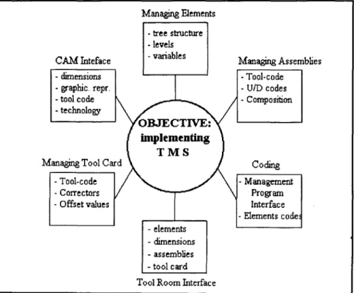
The functions provided by the system include:
b) Automatic generation of coding of the elements to be linked to the analog functions of the company management software.
c) Manual or guided creation of the assembly compositions and automatic generation of the assembly code number and of the geometric parameters of the assembly.
d) Creation of trails with spare parts and inserts.
e) Identification of utilizations through technological research keys.
f) Graphical representation of individual elements and elements of a completed assembly.
g) Generation of tool cards and monitoring of the elements utilized.
h) Interface with the CAM system allowing transfer of assembly geometries and connection between the two environments.
i) Interface with the Tool Room Software.
Managing Elements
CAM Inteface - dimensions - graphic. repro - tool code - technology
Managing Tool Card - Tool-code - Correctors - Offset values
- tree structure -levels - variables
- elements - dimensions - assemblies - tool card Tool Room Interface
Managing Assemblies - Tool-code
- UID codes - Composition
Coding - Management
Program Interface - Elements code
4.
File structure
Data regarding elements (tools, mandrels, accessories, etc.) are stored in the DB for subsequent processing by the program for the purpose of executing the various operations of association, search and linkage necessary to enable the required functions.
The objective to be attained was that of classifying the elements according to criteria of grouping and subdivision into levels, reflecting either the common or the specific nature of certain characteristics of the objects. Groups or sub-groups are thus established with the precise aim of making the object immediately identifiable.
Subdivision is obtained through a tree with 4 levels of grouping. This kind of subdivision must be established by the user of the file, who will also specify the criteria for classification and grouping.
In the case in question, the following structure has been defined:
1) AREAS: represent, as a general rule, the different processes in which a tool can be utilized or the different functions it can carry out. For example:
milling, turning, components ....
2) TYPES: for each area it is possible to distinguish macroscopically between integral tools (U), tool carriers (P), accessories (A) and so on. The letter enclosed in parenthesis indicates the type
of object which is utilized in warehouse management of the Tool-Room software. 3) FAMILIES: From this level on, the work of grouping is carried out to meet the specific requirements of the company. In general, in passing from one level to another, one or more characteristics of the elements which are to be entered are specified. Accordingly, the organizer of the library is responsible for deciding which properties of the object should be evidenced starting from the "highest" levels.
For example, after the group (type) of milling cutters has been specified, a more detailed description is given which serves to identify the distinct sub-groups (families), which are still very numerous; for example, there will be the family of the face mills with inserts, the family of the cylindrical end mills, etc.
4) SUB-FAMILIES: this is the last level of grouping of elements and is obtai.ned by specifying, for each family, a partIcular combination of variables
エ・イセ・、@ standardized. For example,
」ケャュセイゥN」。ャ@ end mills in HSS for
rough-mach.mmg (as compared to the previously mentioned family, it is specified that the material is a super-high-speed steel and the structural characteristics are designed for rough-machining operations).
type, the variables in characteristics, always of alphanumeric type, mayor may not be pre-defined.
For example, cylindrical end mill in HSS for rough-machining f = 50 mm ,
height = 36 mm, construction DIN N, coated with TiN.
The examples described, taken from the structure which has actually been realized, are given exclusively for the purpose of defining the means available for organizing the file.
5. Coding the elements
The coding system adopted refers to a mono-code structure; since only the function of identification is required, the code is as brief as possible. Moreover, this structure is in perfect accordance with the hierarchical scheme of classification used for the management software packages with which it had to be aligned. Accordingly, a 12-digit code of numerical type was selected.
The program can generate the code automatically and then transfer it to the management Software, which is the instrument utilized to control materials in circulation, including tools.
6. Defining variables
Each element is described by a more or less complex group of variables. In developing the system it was necessary to
identify, in its entirety, the whole group of variables to be utilized for classifying the elements.
Basically, these consist of two groups: Group I: the variables which describe the properties of a set of elements and which are thus managed in the "high" level description of the element.
This group contains a single type of variables termed standardized. These are pre-established by the organizer of the library, who can thus furnish options, "suggesting" the selection, Le., the value that they can assume. The standardized variables serve to identify within a family the sub-groups having common characteristics. An example referring to the family of cylindrical end mills with shell is the following: (Table I)
Group II:
variables which describe in detail the morphological/dimensional
characteristics of the individual elements.
In this group the following may be noted:
- normalized variables:
- numerical ( e.g., diameter, working length, nO of teeth ... )
- alphanumeric ( e.g., cooling, supplier, denomination ofISO inserts ... ) they can also be grouped either with reference to a precise area or with genera1 validity.
- pre-established variables or types of attribute:
Standardized Variables
1. Specific type: End Mill
2. Construction characteristics
3 ... .
Options
a. helical tooth finishing cutter b. rough-machining chip breaker c. semi-finishing chip breaker d. with straight teeth for flattening ( XO =75)
e. with straight teeth for shoulders ( XO =90)
a. type N (Mat. with Rs> 500mm2 )
b. type H
c. type W (Mat. with Rs
<
500mm2 ) d. construction for stainless steels e. construction for titanium. a ... .Table 1
7.Characterization
of
- Derived from Standardfamilies
In general, a company which produces small lots utilizes commercially available tools, tools modified in respect to the "commercial" type and tools specially designed for the production of a detennined product. This distinction gives rise to the following definition of tool classes
-Standard (STD)
-According to Drawing.
In the last two cases it will be possible to take from an SID family, en bloc, the set of variables already adopted, which can then be modified or completed very quickly.
Tool-room management also requires that at this stage a distinction be made between groups of elements that are not perishable (e.g., toolholders for lathe or
and simple elements which can be
regenerated or reground (e.g., tools made
ofHSS).
It is then possible to characterize the families of compositions and of
assemblies, for the purpose of creating
libraries of pre-assemblies or assemblies. The latter are then treated like any other elements and grouped in families.
8.
Assemblies module
A simple tool such as a drilling bit or a milling cutter of any type cannot be mounted directly on the mandrel of modern numerical control machines but requires, at minimum, a toolholder equipped with fitting designed according to standards, ISO for instance.
The need to perform particular machining operations as well as the use of modular components has complicated still further the realization and management of these assemblies. Accordingly, standardization of their utilization which is recognized by both CAM programmers and tool-room operators is needed. When working cycles are programmed it is absolutely necessary to establish exactly how the tool will be mounted and what are the most important nominal dimensions. When the assemblies module is enabled, all of the necessary components can be selected semi-automatically. Starting from the basic element, i.e., the tool, all of the other elements are selected upstream of it, towards the mandrel. After having
reached the element of connection with the machine it is possible to recall any other elements downstream such as hard metal inserts in the case of drilling tips with inserts or turning tools with inserts. Association between two elements in the composition of an assembly takes place through the recognition of a common variable that describes the coupling mode.
Since tools and toolholders are constructed according to international standards (UNI, DIN,ISO) all of the dimensions of the object, in the specific case the connection devices, are known beforehand. This is the typical case where the library manager can create a pre-established variable, i.e., a type of attribute which for this application is denominated
Upstream-Downstream Code (UID) .
Each UID code is thus an attribute which, containing dimensional references relevant to the individual element, is assigned on the local level. The utilization of this type of variable makes it possible to disregard the code numbers of the individual elements which, in addition to being more numerous than the coupling types, could never be pre-established and thus would not allow automatic composition.
PRODUCAO
Management of the numerical variables calls for the creation of rules for composition which allow, at the moment when the individual assemblies are entered, automatic fetching of the numerical values of each stored element to obtain the resulting data (from sums, subtraction or evaluation of minimums and maximums) of interest in the specific application.
9.
Graphic representation
The system contains a program for the implementation of a library of graphic files in DXF format which represent the different types of tools with their basic geometry and dimensions.
The standard format of the file also allows for personalization ofthe graphics through the CAD system utilized in the company. In the case of assemblies, global graphical representation of the assembly is automatically obtained by recalling all of the graphic files of the individual components belonging to the specific assembly.
to.Conclusions
and
developments
In the development of this work, the characteristics and architecture of a Tool Management System have been completely defined and operating modes have been established for its correct utilization within the company by all of the departments using tools. The basic
nucleus of the System, consisting of the tools Data Base, the DB management procedures and application programs allowing coding of tools, filing of them, the execution of assemblies and the compiling of tool cards has then been developed and perfected, as described above. Modes of interface with the Tool-Room software and with the CAM programming systems have been devised.
Now in the stage of development is the "Technological Research" module for automatic selection of tools interfaced with a CAD-CAM features-oriented system, which will be used to select in a simple manner the features to be machined and thus to obtain directly from the pattern all of the necessary data for tool selection.
A further step ahead will be that of developing a module for filing and processing of cutting data, in ッイ、セイ@ to associate to the selected tools the most suitable technological parameters which take account of the specific characteristics ofthe machining process to be carried out, and of the operating methods associated with machine tools, materials, equipment, and production criteria.
Bibliography
KRAUSE F., KIMURA F., KJELBERG T., LU S.C. "Product Modeling"-Annals of CIRP K. P.,1993
VAN HOUTEN F.J. "Manufacturing
H.A. ELMARAGHY "Evolution and Future Perspectives of CAPP "-Annals of CIRP K.P., 1993
TORVINEN S.J., SALMINEN K., VASEK L. "Integration of a CIM tool-management to an intelligent feature based process planning system "
Computers in Industry, Nov. 1991
AA. Vv. " Tool Management: The Present and the Future "-Annals of CIRP K.P., 1991
BOSCO W.M. CHAN "Tool Managementfor flexible manufacturing"
Int. J. of Computer Integrated Manufacturing, May 1992
ABRAHAM B., FALKENBURG D.R.
"Tool Managementfor FMS."-Annals of CIRP,1985
KASTELIC S., KOPAC J., PEKLENIK 1. "Conceptual Design of a Relational Data Base for Manufacturing Processes",-Annals of CIRP,1993
BRUNETTE M.R. "Presetting for tool-management systems "- Tooling &
Production, June 1989
BRANDI MARTE P., CALDERINI M., CANTAMESSA M., LOMBARDI E, ROSSETTO S., VILLA A. "Gestione integrata del sistema /ogistico per utensi!i"- W. Ann. Progetto di ricerca Murst 40%, 15 Giugno 1993
GINDY N.N.Z., HUANG X., RATCHEV T.M. " Feature Based component model computer-aided process planning systems"- Int. J. of Computer Integrated Manufacturing, Junel993
ANTONELLI D., DINI G., GIARDINI C., MORONI G., PIACENTINI M. "Generazione automatica dei cieli integrati di lavorazione e controllo "- Atti IV Convegno AITEM Ancona, 22-24 Sett, 1993.
FENTON R.G., GAGNON M.F.J.
"Computer-Aided Tool Material Selection for Metal Cutting operations
"- Annals of CIRP, 1993