*e-mail: [email protected]
1. Introduction
For the past two decades, the application of numerical simulation which can help researchers solve sophisticated
problems has made signiicant contributions to materials
science and metallurgical industry due to its functions1-5. As an important branch of the industrial system, metallic glass have
been commercialized in several ields such as engineering,
medicine, electronics, military, sports, and jewelry making for a period of time6-10. A variety of bulk glassy alloys have been developed in lanthanide (Ln)-[11], Mg-[12], Zr-[13,14], Be-[15], Fe-[16], Pd-Cu-[17], Ti-[18], Ni-[19], Co-[16] and Cu-[20] based the systems by various slow cooling producing processes such as copper mold casting and water quenching etc. Among these bulk metallic glass systems, Zr-based alloy systems are the most important alloy systems because it conjuncts the achievement of various useful engineering properties with high glass-forming ability. Xingguo Zhang and his colleagues developed a new continuous casting method for the massive production of bulk metallic glass ingot with centimeter-scale diameter while has no limitation in length21 in their research paper. An intermittent withdrawal procedure was practiced for continuous casting of bulk metallic glass. The new continuous casting method can provide a cooling speed as fast as that provided by die mold casting method.
However, the solidiication process is dificult to be
measured and recorded in the surrounding of high temperature and vacuum. The complicated conditions of BMG fabrication
which requires a rapid cooling rate also increase the dificulty to study the temperature ield. The method of numerical
simulation provide a possibility to measure and investigate the thermal parameters and cooling rate of the metallic glass. Thus, the method of numerical simulation is an effective,
low-cost and time-saving way to study the solidiication
process of continuous casting for the production of bulk metallic glass ingot.
In this paper, the temperature ield of continuous casting
ingot of bulk metallic glass was selected as a research object. The analysis will be given after comparing the results of the
numerical simulation with the experimental results. As a inite
element analysis software, ANYSYS was used to study the
effects of processing parameters on the temperature ield and provide theoretical basis for optimizing the solidiication process.
2. Experimental Procedure
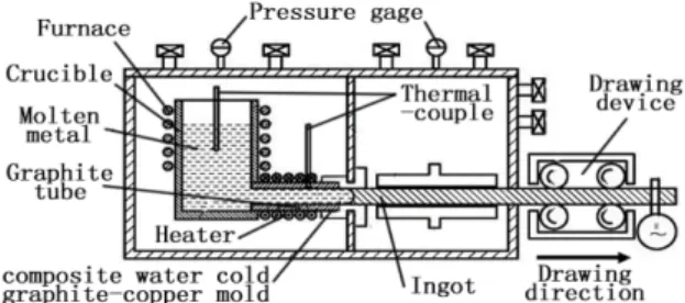
Alloy ingots with nominal compositions of Zr48Cu36Al8Ag8 were prepared by arc melting mixtures of Zr, Cu, Al and Ag with a purity of 99.99%, 99.99%, 99.99% and 99.9%, respectively, in a Zr-gettered high purity argon atmosphere. Ribbon samples were prepared by melt spinning. The thermal stability associated with glass transition, super cooled liquid region and crystallization was examined by differential scanning calorimeter (DSC) at a heating rate of 0.67 K/s. The device of continuous casting is shown in Figure 1, each ingot was melted four times in the arc meter to avoid the chemical heterogeneity and remolded in the graphite crucible inside the furnace, the molten metal is
solidiied in the mold which is made of a composite of graphite
tube and copper, withdrawing speed is control by withdrawing device. Cylindrical rod samples with a diameter of 10 mm were prepared by this continuous casting method in an argon atmosphere. The Optical microstructure were obtained with optical microscopy (OM), the etching for OM observation
specimens was made in an aqueous luoride solution for 5 s at
298 K. The structure of the as-cast samples was examined by
X-ray diffraction (XRD) with Cu-Kα source.
Numerical Simulation of Zr-based Bulk Metallic Glass During Continuous
Casting Solidiication Process
Renhong Tanga, Bingwen Zhoua,Yuejiao Maa, Fei Jiaa*, Xingguo Zhanga
aSchool of Materials Science and Engineering, Dalian University of Technology, Dalian 116024, China
Received: August 22, 2014; Revised: April 12, 2015
A numerical simulation method was used to analyze the solidiication process of Zr-based bulk
metallic glass (BMG) during the horizontal continuous casting (HCC) process. The large-scale
general-purpose inite element analysis software ANSYS was adopted to develop a temperature ield model. The variation of temperature ield in the speciic area at different time was studied. Its accuracy was veriied by the experimental results of Zr48Cu36Ag8Al8 bulk metallic glass continuous
casting solidiication process. The effects of casting parameters include intermittent casting procedure
(drawing and stopping), casting speed, pouring temperature and cooling rate. The results show that the optimum casting speed range is 1-2 mm/s, pouring temperature is 1223 K and cooling rate of 10 mm rod casting is 5 L/min respectively. A fully Zr-based bulk metallic glass whose diameter is 10 mm and length has no limitation has been successfully fabricated.
Keywords: bulk metallic glass, continuous casting, composite water cold copper-graphite mold,
3. Mathematical Model Formulation
3.1. Basic assumptions in modeling
(1) The continuous process is continual and stable, meanwhile, the composition of the molten metal is constant;
(2) The heat transfer on the diameter direction was considered, the heat transfer on the drawing direction was neglected;
(3) The area of the cross section is recognized constant,
the heat transfer and solidiication was analyzed, the inluences of shrinkage and turbulent low inside the molten alloy during solidiication process was
neglected;
(4) The latent heat of crystallization was neglected;
(5) The calculating area is selected as the 1/4 cross section of casting due to its geometric symmetry;
(6) For casting velocity item, adopting time –varying boundary conditions and the casting velocity is recognized constant.
3.2. Heat transfer equation
The temperature ield during casting was calculated
based on the heat conduction differential equation of Fourier three-dimensional unsteady heat conduction equation22:
( )
( )
( )
( )
p p
T T T
k T k T k T
x x y y z z
T T
q c C T
z t ∂ ∂ + ∂ ∂ +∂ ∂ + ∂ ∂ ∂ ∂ ∂ ∂ ∂ ∂
− ρ ν = ρ
∂ ∂
(1)
Where x, y and z are spatial coordinate axes; T is temperature; k(T) is the heat transfer coeficient variation with temperature; q is the heat resource inside the casting;
ρ is the density; Cp(T)is the speciic heat capacity variation with temperature; t is the time; p
T c
z
∂
ρ ν∂ is heat transfer cause by the movement of the casting.
Based on the assumptions above, by the selection of a micro unit and the movement with the casting in the same velocity, the two-dimension cross section heat conduction
equation of the casting could be simpliied as:
( )
( )
p( )
T T T
k T k T C T
x x y y t
∂ ∂ + ∂ ∂ = ∂ ρ
∂ ∂ ∂ ∂ ∂ (2)
3.3. Initial and boundary conditions
In this paper, the irst and second categories boundary conditions for the analysis of solidiication process of
molten metal in the water cold graphite-copper mold can
be classiied as follow:
The boundary conditions in graphite tube:
(
)
(
)
0
T |Γ=T ; T |Γ=f r, , t ; θ T|Γ=f r, ,θt (3) Γ is the boundary of object; T0 is known temperature; f(r, θ,t) is a function of known temperature.
The heat low(W/m2) of casting surface can be deduced by a function of time that the casting stay in the composite water cold copper-graphite mold, according to the actual
experiment conditions, the speciic parameters of the mold and the velocity of drawing, the heat lux density function
has been calculated as:
q= −A B t (4)
Where q is heat lux density; A is the heat lux density of initial cross section at the inlet of the mold; B is a heat
transfer coeficient; t is the time casting staying in the composite water cold copper-graphite mold.
The numerical simulation can be calculated based on
the boundary condition of heat lux varied with time after
ascertaining the value of A and B. It is recognized that the
local heat lux density between the molten metal and cooling water is equal to the local heat lux density between the
casting and the composite water cold copper-graphite mold:
w Ts Tw q 1 Rs Rc h − =
+ + (5)
s s s
R = σ λ/ (6)
c c
R = σ λ/ c (7)
Ts is the solidus temperature of the molten metal,Tw is the temperature of the cooling water, Rs is the heat resistance of
graphite tube, σs is the thickness of graphite tube, λs is the
heat conductive coeficient of graphite tube, Rc is the heat
resistant of the copper mold, σc is the thickness of copper
mold, λc is the heat transfer coeficient of copper mold, hw is the heat transfer coeficient between copper mold and cooling water.
pw w
0.8 0.4
w w w w
w w
C u D
h 0.023 ( ) ( )
D
µ λ ρ
= µ λ (8)
D is the diameter of water low inside the mold; λw is the
heat transfer coeficient of water; ρw is the density of water; uw is the average low rate of water; μw is the viscosity of water; Cpw is the speciic heat of water; according to Equation 4 and 5,when t = 0, A = q0 (means A is recognized
to be the heat lux density of initial cross section at the inlet
of the mold.
s c w
Ts Tw A
R R 1 / h
−
= + + (9)
After calculations, Q1 (heat inside the mold) is equal to Q2 (heat taken by water)
1
2 Q Lh A B h / v
3
= −
(10)
2 pw w
Q =C wρ ∆T (11)
L is the inner girth of composite water cold copper-graphite mold;h is the height of composite water cold copper-graphite mold; v is the speed of drawing the casting; w is the velocity
of water low; ∆T is the temperature difference of cooling water. Thus:
(
)
1 2
pw w 3
2 3
B LhA C w T
2Lh
υ
= − ρ ∆ (12)
Every parameter in the calculation of heat lux density
in this paper is shown in Table 1.
4. Numerical Simulation of Temperature
Field
4.1. Outline of continuous casting numerical
simulation
According to the analysis of Zr-based BMG thermal parameters and the mathematics model established above, the
temperature ield of Zr48Cu36Al8Ag8BMG during continuous
casting process was simulated by ANSYS, the speciic steps
are listed below. Cooling rate is an essential factor during the
continuous casting process, and rapid cooling is beneicial
to obtain a full glass structure. But in the meanwhile, with the decreasing of temperature, the viscosity of the molten
metal was increasing rapidly, which led to a bad mold illing
and failure. In order to solve this problem, a composite graphite-copper mold was used to achieve both of rapid
cooling speed and favorable mold illing.
Step 1: Establishing two-dimensional geometric model of casting;
Step 2: Typing in the thermal parameters of alloy;
Step 3: Plotting the inite element mesh;
Step 4: Appling the initial and boundary condition;
Step 5: Solving the temperature ield of casting in the
graphite tube;
Step 6: Substituting the result into solidiication model
as the initial condition;
Step 7: Appling the boundary condition of heat lux
density;
Step 8: Solving the temperature ield of the casting in
the copper mold;
Step 9: Discussion and analysis;
Step 10: Experimental veriication.
4.2. Geometric model and mesh plotting
Due to the symmetric shape of casting, the meshes of a quarter of the ingot were plotted by ANSYS, shown in Figure 2.
4.3. Simulation results and analysis
The heat analysis model of ANSYS was used, the unit type as PLANE55 and analysis type as Transient was selected. The initial temperature was applied by command
stream BFUNIF, TEMP or Solution, Deine Loads, Apply,
Thermal, Temperature, Uniform Temp.
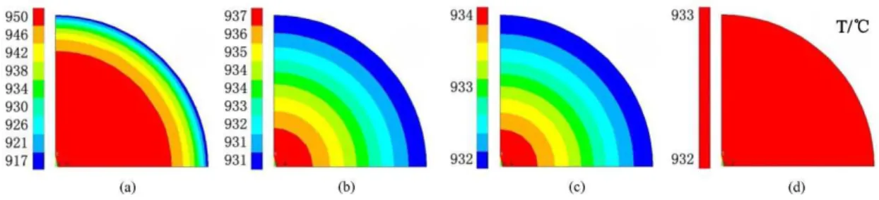
Figure 3 denotes that the cooling rate on the surface is the fastest and it decrease gradually along the radial direction from the surface to the inside. Then the temperature differences
become smaller as time passed and the temperature ield
Table 1. The parameters in heat lux density.
Parameters/Unit Ts/K Tw/K Rc/ m
2Kw–1 R
s/ m 2Kw–1
Value 821 288 7.5×10⁻⁵ 1.55×10⁻⁵
D/m λw/ Wm–1K–1 ρ
w/ kgm
–3 u
w/ ms –1
0.023 0.618 998.2 0.0684
Cpw / Jkg–1K–1 L/m h/ m W/ m3s–1
4183 0.0314 0.04 8.33×10⁻⁵
hw /Wm
–2K–1 μ
w/ PaS ∆T/K
525.2 7.921×10⁻⁴ 1
becomes regular and stable in 5 s. It predicts that the graphite has a cooling effect to the molten metal.
The inal temperature of molten metal in the exit of the
graphite tube was selected as the initial condition; the order
of Solution |Deine Loads | Apply | Thermal | Temperature |
Heat Flux |On Lines was applied as the boundary condition
of heat lux density with loading the function of heat lux
density which was established before. By solving the Euler equation, the total computation time is 26 s.
In Figure 4, the radial temperature distribution of casting has been entered the composite water cold copper-graphite mold for 0.1 s, 5 s, 15 s, 26 s respectively, which predict the change and cooling rate of the casting during continuous casting. The temperature of the molten metal began to decrease after entering the composite water cold copper-graphite mold. The cooling rate of the exterior is faster than the cooling rate of the interior, and the temperature of whole casting drops below the glass forming temperature after 26 s.
Figure 5 shows the relationship between withdrawing speed and cooling rate of continuous casting under the conditions of TP=1223 K and Q =5 L/min. With the withdrawing speed increasing from 1 mm/s to 1.5 mm/s and 2 mm/s, the average cooling rate between TM and TG decrease from 28 K/s to 24 K/s and 21 K/s.
5. Experimental Process
5.1. Experiment of continuous casting
In order to keep the coherence and pureness of the alloy, the Zr48Cu36Al8Ag8 alloy is remelted in graphite crucible under high purity argon atmosphere, at a rated temperature of 1223 K for 30 min before the rod is withdrawn at different
speeds to offer the molten metal a luctuant cooling rate.
The weight of the alloy remains between 300 g and 350 g. The pouring temperature (TP) is 1223 K, and soaking time
30 min, low speed of cooling water (Q) 5 L/min, and
drawing speed 1 mm /s, 1.5 mm /s, and 2 mm /s respectively for No. 1#, No.2#, and No.3# samples.
5.2. Results and analysis of the experiment
The No. 1# rod sample for continuous casting experiment is shown in Figure 6, and the XRD sample was taken from the blaze position of the rod, as shown in Figure 6. A typical diffuse scattering peak which indicates a fully amorphous structure can be seen. When the rod sample was under the conditions of TP= 1223 K, Q=5 L/min, with an applied drawing speed of1mm/s, the temperature of molten metal in the graphite tube(before entering the mold) decreased, which led to the increase in its viscosity, due to the low drawing speed. Therefore, the rod sample made it easy to get abruption under semisolid condition.
The optical micrograph of the cross section is shown in Figure 6. No crystal phase was found in the cross section, which is consistent with XRD result.
The No. 2# rod sample for continuous casting experiment is shown in Figure 7. The XRD samples were taken from
these ive positions of the rod, as shown in Figure 7. A typical diffuse scattering peak which indicates a fully amorphous structure can be seen.
As shown in Figure 7, a diffuse scattering peak appeared at about 2θ=38.1°, and there was no crystal diffraction peak found. OM images in different multiples are shown in Figure 7. It can be seen that no crystal phase was found in the whole zone, indicating that the sample had a single-phase amorphous structure.
Figure 8 shows the DSC curves of the Zr48Cu36Ag8Al8glassy alloy, with TG=703 K andTX=801 K. Both of them are marked with arrows respectively, with ∆T=98 K. The glassy sample exhibits a distinct endothermic heat event characteristic of the glass transition, followed by exothermic transformation from the undercooled liquid to the equilibrium crystalline phases.
Figure 3. Temperature distribution contour at different time in the graphite mould (a) 0.1s, (b) 2.5s, (c) 4.5s, (d)5s.
The No. 3# rod sample for continuous casting experiment is shown in Figure 9. The XRD samples were taken from
these ive positions of the rod, as shown in Figure 9. There was a crystal phase in each cross section to different extents, and the crystallization behavior increased with the casting progresses. The main reason lies in that the drawing speed is too fast to provide enough time for cooling down the
molten metal, which remains at a quite high temperature and has left the mold. Besides, the casting releases a lot of heat
and affects the subsequent solidiication process due to the
crystallization behavior.
The sample of optical micrograph was taken at the initial and the end of the casting respectively, as shown in Figure 9. It can be seen that few crystal phase precipitated at the initial stage, while there were much more crystal phases at the end of the casting.
5.3. Comparison between numerical results and
experimental results
Cooling rate is a signiicant factor for glass forming.
A fully glassy structure could be obtained when the temperature of the molten metal has dropped below that of amorphous transfer at a cooling rate higher than the critical cooling rate of the alloy. The simulation of continuous casting is calculated under the conditions of Tp=1223K and Q=5L/min, when the drawing speed is applied at 1mm/s, 1.5mm/s, and 2mm/s, respectively. The simulation and experimental results were compared with each other and analyzed as follows: Figure 5. Temperature-Time curve of the hot point with different
casting speeds.
Figure 6. XRD patterns of samples from blaze positions. The insets illustrate the Zr48Cu36Al8Ag8 alloy rod and optical microstructure
of the cross section.
Figure 7. XRD patterns of samples from different positions of Zr48Cu36Ag8Al8. The insets illustrate the sample of Zr48Cu36Ag8Al8 alloy rod and optical microstructures of the cross sections.
Figure 8. DSC curve of continuous casting Zr48Cu36Ag8Al8 alloy rod.
Figure 9. XRD patterns of samples from different positions of Zr48Cu36Ag8Al8. The insets illustrate the sample of Zr48Cu36Ag8Al8
In this experiment, the average cooling rate of the casting remained at about 28 K/s between Tm and Tg, when the drawing speed was 1 mm/s, and the temperature of the casting surface decreased to the temperature of glass transfer after its entering the composite water cold copper-graphite mold for about 17 s, while the casting center would cost 19 s. However, both of them met the condition of the glass forming of Zr48Cu36Ag8Al8 alloy.
The average cooling rate of the casting remained at about 24 K/s between TM and TG when the drawing speed was 1.5 mm/s. The temperature of the casting decreased to TG at the position of 6 mm away from the end of the mold, whereas the temperature of the casting center decreased to 575 K which was lower than TG and met the condition of glass forming at the end of the mold. A Zr48Cu36Ag8Al8 alloy rod with a diameter of 10 mm and length of 380 mm was fabricated at a drawing speed of 1.5 mm/s in this experiment. This sample was determined as a Zr48Cu36Ag8Al8 bulk glass metal with the method of XRD.
The average cooling rate of the casting remained at about 21 K/s between Tm and TG when the drawing speed was 2 mm/s. At the exit of the mold, the temperatures of casting center and surface were 763 K and 729 K respectively, both of them higher than TG and lower than TX. The casting will crystallize when the temperature stay above TG, and the crystallization
behavior will affect the temperature ield and lead to more
crystallization behavior.
6. Conclusion
According to the results of the numerical simulation,
the variation of drawing speed signiicantly affects the inal distribution of temperature ield. The cooling rate decreases while the inal temperature of casting rises with the increase
in drawing speed. The experiment was conducted under the following conditions: The pouring temperature is 1223 K,
low speed of cooling water 5 L/min, applied drawing speed
at1mm/s, 1.5mm/s, and 2mm/s, respectively, as well as the average cooling rate of the molten metal between TM and TG at about 28 K/s, 24 K/s and 21 K/s, respectively, which meet the condition of glass forming. The rod sample with a processing parameter of 1# cooled down and became sticky,
hindering the subsequent mold illing and easily leading to the
failure due to the low speed. The rod sample with a processing parameter of 3# exhibited blaze metallic luster. However, the drawing speed was too fast to provide enough time for forming metallic glass. The rod sample with a processing parameter of 3# was a fully Zr-based bulk metallic glass with a diameter of 10 mm and length of 380 mm, which would be a desirable production for horizontal continuous casting.
Acknowledgements
The research was financially supported by the National Natural Science Foundation of China (Grant No. 51301029 and 51375071) and the Fundamental Research Funds for the Central Universities (DUT11RC(3)86).
References
1. Park H-S, Nam H and Yoon JK. Numerical analysis of fluid flow and heat transfer in the parallel type mold of a thin slab caster. ISIJ International. 2001; 41(9):974-980.
2. Ghiţă C, Pop N and Popescu IN. Existence result of an effective stress for an isotropic visco-plastic composite. Computational Materials Science. 2012; 64(11):52-56. http://dx.doi.org/10.1016/j. commatsci.2012.03.058.
3. Crăciun EM, Carabineanu A and Peride N. Antiplane interface crack in a pre-stressed fiber-reinforced elastic composite. Computational Materials Science. 2008; 43(1):184-189. http:// dx.doi.org/10.1016/j.commatsci.2007.07.028.
4. Ionescu A, Nicolicescu C, Bucşe I and Ghercioiu J. Modelling and simulating the pressing process of iron powders with different particle sizes. In: International Conference on Economic Engineering and Manufacturing Systems. 2011; Craiova. Craiova: University of Craiova; 2011. p. 307–310. 5. Dagner J, Friedrich J and Müller G. Numerical study on the
prediction of microstructure parameters by multi-scale modeling of directional solidification of binary aluminum–silicon alloys. Computational Materials Science. 2008; 43(4):872-885. http:// dx.doi.org/10.1016/j.commatsci.2008.02.002.
6. Telford M. The case for bulk metallic glass. Materials Today. 2004; 7(3):36-43. http://dx.doi.org/10.1016/S1369-7021(04)00124-5. 7. Fujita K, Hashimoto T, Zhang W, Nishiyama N, Ma C, Kimura
HM, et al. Advanced high-strength and ductile Fe-Cr-Mo-Ga-Si alloys. Reviews on Advanced Materials Science. 2008; 18(2):140-143.
8. Kumar G, Tang HX and Schroers J. Nanomoulding with amorphous metals. Nature. 2009; 457(7231):868-872. http:// dx.doi.org/10.1038/nature07718. PMid:19212407.
9. Saotome Y, Okaniwa S, Kimura HM and Inoue A. Superplastic nanoforging of Pt-based metallic glass with dies of Zr-BMG and glassy carbon fabricated by focused ion beam. Materials Science Forum. 2007; 539–543:2088-2093. http://dx.doi. org/10.4028/www.scientific.net/MSF.539-543.2088.
10. Nishiyama N, Amiya K and Inoue A. Novel applications of bulk metallic glass for industrial products. Journal of Non-Crystalline Solids. 2007; 353(32-40):3615-3621. http://dx.doi. org/10.1016/j.jnoncrysol.2007.05.170.
11. Inoue A and Zhang T. Fabrication of bulk glassy Zr55Al10Ni5Cu30 alloy of 30 mm in diameter by a suction casting method. Materials Transactions. 1996; 37(2):185-187. http://dx.doi. org/10.2320/matertrans1989.37.185.
12. Yokoyama Y, Mund E, Inoue A and Schultz L. Production of Zr55Cu30Ni5Al10 glassy alloy rod of 30 mm in diameter by a
cap-cast technique. Materials Transactions. 2007; 48(12):3190-3192. http://dx.doi.org/10.2320/matertrans.MRP2007164.
13. Zhang W, Zhang QS, Qin CL and Inoue A. Synthesis and properties of Cu-Zr-Ag-Al glassy alloys with high glass-forming ability. Materials Science and Engineering: B. 2008; 148(1-3):92-96.
14. Johnson WL. Fundamental aspects of bulk metallic glass formation in multicomponent alloys. Materials Science Forum. 1996; 225–227:35-50. http://dx.doi.org/10.4028/www.scientific. net/MSF.225-227.35.
15. Inoue A, Nishiyama N and Kimura HM. Preparation and thermal stability of bulk amorphous Pd40Cu30Ni10P20 alloy cylinder of 72
mm in diameter. Materials Transactions, JIM. 1997; 38(2):179-183. http://dx.doi.org/10.2320/matertrans1989.38.179.
metallic properties. Materials Transactions. 2009; 50(10):2441-2445. http://dx.doi.org/10.2320/matertrans.MRA2008453.
17. Zheng Q, Xu J and Ma E. High glass-forming ability correlated with fragility of Mg–Cu(Ag)–Gd alloys. Journal of Applied Physics. 2007; 102(11):113519. http://dx.doi.org/10.1063/1.2821755.
18. Li R, Pang S, Ma C and Zhang T. Influence of similar atom substitution on glass formation in (La–Ce)–Al–Co bulk metallic glasses. Acta Materialia. 2007; 55(11):3719-3726. http://dx.doi. org/10.1016/j.actamat.2007.02.026.
19. Jiang QK, Zhang GQ, Chen LY, Wu JZ, Zhang HG and Jiang JZ. Glass formability, thermal stability and mechanical properties of La-based bulk metallic glasses. Journal of Alloys and
Compounds. 2006; 424(1-2):183-186. http://dx.doi.org/10.1016/j. jallcom.2006.07.109.
20. Zhang QS, Zhang W and Inoue A. Preparation of Cu36Zr48Ag8Al8 bulk metallic glass with a diameter of 25 mm by copper mold casting. Materials Transactions. 2007; 48(3):629-631. http:// dx.doi.org/10.2320/matertrans.48.629.
21. Zhang T, Zhang X, Zhang W, Jia F, Inoue A, Hao H, et al. Study on continuous casting of bulk metallic glass. Materials Letters. 2011; 65(14):2257-2260. http://dx.doi.org/10.1016/j. matlet.2011.04.033.