*e-mail: [email protected]
Presented at the International Symposium on High Temperature Corrosion in Energy Related Systems, Angra dos Reis - RJ, September 2002.
Stress and Integrity Analysis of Steam Superheater
Tubes of a High Pressure Boiler
Daniel Leite Cypriano Nevesa*, Jansen Renato de Carvalho Seixasa, Ediberto Bastos Tinocob, Adriana da Cunha Rochac, Ibrahim de Cerqueira Abudc
aPETROBRAS, REDUC, Industrial Maintenance, Equipment Inspection,
Duque de Caxias - RJ, Brazil
bPETROBRAS, CENPES, Basic Equipment Engineering, Rio de Janeiro - RJ, Brazil
cINT, Laboratório de Metalografia e de Dureza, Rio de Janeiro, RJ, Brazil
Received: September 2, 2002; Revised: September 4, 2002
Sources that can lead to deterioration of steam superheater tubes of a high pressure boiler were studied by a stress analysis, focused on internal pressure and temperature experienced by the material at real operating conditions. Loss of flame control, internal deposits and unexpected peak charge are factors that generate loads above the design limit of tube materials, which can be sub-jected to strain, buckling, cracks and finally rupture in service. To evaluate integrity and depend-ability of these components, the microstructure of selected samples along the superheater was studied by optical microscopy. Associated with this analysis, dimensional inspection, nondestructive testing, hardness measurement and deposit examination were made to determine the resultant material condition after twenty three years of operation.
Keywords:superheater, high temperature damage, boiler
1. Introduction
Superheater tubes are surfaces for heat exchange, with the object of increasing the steam temperature, after it comes from the boiler drum, to a value higher than saturation. This has two basic purposes: to increase the thermodynamic ef-ficiency of the turbine, in which the steam will be expanded; and to make the steam free of humidity. In normal opera-tion, the boiler analyzed in this paper, named REDUC/SG-2001, produces steam that is superheated by approximately 200 °C at the inlet of the turbine. The steam flow has to be intense to permit the heat absorption from the tube, avoid-ing deformation because of high temperature.
The superheater can be divided in two sections, primary and secondary, as in the boiler studied, where the super-heater tubes are within the radiation zone. After nineteen years of service, the primary one showed some tube defor-mation, which had become greater when observed at the last inspection/maintenance shut downs. This residual plas-tic deformation was observed on the outlet tube, attributed to differential dilatation, because of different temperatures
(∆T), between the last two tubes, anchored by spacers, and causing buckling. After that, in December 2001, when the boiler had twenty three years of service, a stress and metalographic analysis was made on an assembly removed from the boiler, involving yet dimensional inspection, nondestructive testing, hardness measurement and deposit examination. The objective was to determine the state of integrity of the material in order to estimate a limit of defor-mation and then indicate the best maintenance service for this equipment, which is critical to the continuity of the re-finery processes. The REDUC boiler is model VU-60, nomi-nal charge 365 ton/h of steam, design pressure 119 kgf/cm2 and operating pressure 104 kgf/cm2.
encountered in a superheater. This can occur particularly by two mechanisms: short-term overheating and high tem-perature creep. In the first one, a single incident, or a small number of incidents, exposes the tube steel to an excessively high temperature (hundreds of degrees above normal) to the point where deformation or yielding occurs. Overheating results from abnormal conditions such as loss of coolant flow, internal oxide layer or flame incidence. The second one is either called long term or extended overheating fail-ures, which results from a relatively continuous extended period of slight overheating, stress, or the accumulation from several periods of excessive overheating. Creep deforma-tion results in little or no reducdeforma-tion in wall thickness, but produces measurable creep elongation or increases in di-ameter in ferritic steel tubes1.
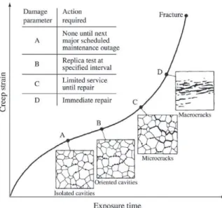
The first published attempt to relate creep-life consump-tion of plant components to cavitaconsump-tion (voids) was that of Neubauer and Wedel2. They characterized cavity evolution in steels at four stages – i.e., isolated cavities, oriented cavi-ties, linked cavities (microcracks) and microcracks – as shown in Fig. 1. Based on observations on steam pipes in German power plants, they estimated the approximate time intervals required for the damage to evolve from one stage to the next under typical plant conditions. They formulated recommendations corresponding to the four stages of cavi-tation (A, B, C, D).
Corrosion is another expected mechanism that can lead superheater tubes to failure. Localized or generalized loss of thickness occurs because of corrosion by the products of combustion (external) or from steam, especially when some
contaminated water, coming from the drum, flows through the superheater (internal) after some process abnormality. This causes increased stress in a tube operating at a con-stant internal pressure. In addition, corrosion is a source for overheating problems, by the formation of an oxide layer, which is a barrier to heat transfer. As its thickness increases, metal temperatures must also increase to maintain a con-stant outlet temperature. Typically, tube metal temperatures increase from 0.6 to 1.1 °C for each 30 µm of internal oxide formed. Allowing for these changing conditions of metal temperature and stress over time is key to reliable creep life prediction of alloy superheater tubes3.
Another mechanism that can lead to failure is fatigue of the tubes. Pressure equipment, unlike rotating machin-ery and aircraft structures, is not usually subjected to large numbers of load cycles during its lifetime, and ductile metals can absorb surprisingly large strains for limited numbers of cycles. When, however, the utmost in reliabil-ity and efficient utilization of material is required it be-comes necessary to calculate pressure stresses and ther-mal stresses in detail and to determine whether or not tigue failure is possible in a few hundred cycles. The fa-tigue curve shows stress or strain versus cycles and which contains sufficient safety factors to give safe allowable operating cycles for a given value of calculated stress. The stress values on the fatigue curves should be directly com-parable to stress values which a designer calculates using his usual methods of analysis for pressure stress, thermal stress, stress concentration, etc4.
Figure 1. Creep life assessment based on cavity classification2.
2. Experimental
A microstructural analysis was made by optical microscopy to compare the state of integrity superheater tube materials from inlet to outlet steam zones. Steam tempera-ture varies from 310 to 450 °C inside the primary super-heater and the gas temperature outside the tubes is approxi-mately 800 °C, within the radiation zone. The quantitative measurements by microscopy were made according to ASTM Standards E 112-965 and E 562-896. For analysis of internal and external layers, to determine their thickness and composition, a scanning electron microscope (SEM) with energy dispersive spectroscopy (EDS) was used.
Ten samples were prepared from pieces of tubes, ex-tracted from an assembly, in the positions shown in Fig. 2. The design steel specifications were confirmed by analysis with alloy analyzer “Metalurgist”, model 9277, by x-ray fluorescence spectrometry, and are indicated in Table 1.
A Rockwell B hardness test was made on sections of the samples, according to standard NBR NM 188-1-99 7. Di-mensional measurements (diameter and thickness) and NDT by liquid penetrant were made along the assembly.
For stress analysis a commercial software, ANSYS 5.4, was used, with the finite element method, to determine the post buckling condition considering the actual geometry of the last two tubes, in the outlet steam zone. The special tube element, Pipe 20, was used, which can analyze situations containing plasticity and large displacement. In normal serv-ice conditions, the average temperature difference between
the last two tubes is about 25 °C, but this can vary, especially when there is some loss of operational control or emergency. A temperature change, “∆T”, of 50 °C between these tubes, which could provoke a lateral deflection, because of a bend-ing-compression of the hottest one, similar to one observed in the assembly studied. After that, cycles of tube heating and cooling, during boiler starting and shutdown, were simulated to find out the time and extent of deformation that could lead to nucleation of fatigue cracking. The material properties considered for the calculations were: elastic modulus (E) (21000 kgf/mm2); yield stress (21 kgf/mm2); and the elastic-plastic modulus (200 kgf/mm2).
3. Results and Discussion
Hardness measurements are described in Table 2. The hardness results are below the maximum allowed by ASTM Standard A2138 (85 HRB) and do not vary greatly along the assembly. It shows that, firstly, this mechanical property of the material is preserved. The tube thickness does not show significant losses caused by corrosion during the time in service. During the last shutdown the medium rate of corro-sion was 109 µm/year, and the residual life was estimated as 14 years, considering local loss of thickness in the calcu-lations.
A dimensional mapping of the assembly was made by measurement of diameters, which did not show any increase, which would indicate an advanced state of creep deforma-tion. Some NDT by liquid penetrant at the spacers’ welds and the curves of the tubes did not indicate the presence of any cracks.
The internal surface was analyzed with the SEM, where a maximum surface layer of 15 µm was observed. EDS re-sults, shown in Fig. 3a, indicated the presence of iron (Fe), chromium (Cr), oxygen (O), phosphor (P) and sulfur (S). These elements come from the formation of a protective layer, containing Fe, Cr and O, and possibly from the water treatment and impurities, especially P and S. Mild decarburization was observed on some samples, numbers 1, 2, 6, 7, 8 and 9, this being normal because of the high temperature and time of service of the equipment and with-out bad implications on its integrity.
On the external surface, the maximum layer was 122.67 µm. EDS results, shown in Fig. 3b, indicated the presence of iron (Fe), silicon (Si) and chromium (Cr) from the steel. Burn residues, which have diffused from the ex-ternal layer, containing vanadium (V), oxygen (O) and sulfur Table 1. Material specifications of the samples indicated on Fig. 2.
Sample Dimensions * Material Observation
1 ∅=50.8; t=7.7 SA-213 Gr.T22
2 ∅=50.8; t=7.7 SA-213 Gr.T22
3 ∅=50.8; t=7.7 SA-213 Gr.T22
4 ∅=50.8; t=7.7 SA-213 Gr.T22 Welded Joint
and 4.8 and SA-213 Gr.T12
5 ∅=50.8; t=4.8 SA-213 Gr.T12 Welded Joint
6 ∅=50.8; t=4.8 SA-213 Gr.T12 Welded Joint
and 6.3 and SA-213 Gr.T22
7 ∅=50.8; t=6.3 SA-213 Gr.T22
8 ∅=50.8; t=6.3 SA-213 Gr.T22
9 ∅=50.8; t=6.3 SA-213 Gr.T22
10 ∅=50.8; t=7.7 SA-213 Gr.T22
*∅ = Tube diameter (mm); t = thickness (mm).
Table 2. Hardness Rockwell B.
Sample 1 2 3 4 5 6 7 8 9 10
Hardness
Figure 3. a) Image of internal layer by SEM and respective spectrum from EDS of point 1 indicated in the figure; b) Image of external layer by SEM and respective spectre from EDS of point 1 indicated in the figure.
Table 3. Percentages of transformed perlite for each sample.
Sample % Transformed Perlite Haz Base Metal
1 90 — —
2 95 — —
3 100 — —
4 90 Some oxide inclusions and Partial spheroidization of pores (randomic distribution) cementite of perlite
5 85 Some oxide inclusions Partial spheroidization of
cementite of perlite
6 85 Some oxide inclusions and Partial spheroidization pores (randomic distribution) of cementite of perlite
7 90 — —
8 85 — —
9 80 — —
(S) were present, indicating the formation of sulfides and other compounds that can lead to a liquid phase, which de-stroys the oxide layer, intensifying the corrosion process.
A microstructural analysis was made specifically look-ing for: creep indications; the presence of pores, aligned carbides or microcracks; and microstructural damage, like carbide spheroidization. In general, a microstructure with a ferritic matrix, pearlite grains and chromium and silicon
carbides, was found for both the grade T12 and T22 steels. The grain size obtained was the ASTM 6 (φ = 44.9 µm), except for sample 10, which was a little larger – ASTM 5,5 (φ = 53.4 µm). The results for some samples are shown in Fig. 4.
either at carbide boundaries and matrix. Aligned or coa-lesced carbides weren’t found, neither microcracks, which indicates that the material didn’t reach an advanced stage of creep, as described on the literature3. However, it was ob-served that in the pearlite phase, for the T22 and T12 steels, a process of spheroidization of cementite had initiated. The region that primarily suffers a flame incidence, sample 3, has the biggest percentage of transformed pearlite, as shown in Fig. 4b. A smaller percentage is observed on sample 10, Fig. 4a, which lay beyond the bottom refractory, at a lower temperature. Sample 8, where buckling of the tube was ob-served, showed an intermediate degree of transformation of cementite. The percentages for each sample are shown in Table 3. These percentages correspond to a fraction of pearlite at the beginning of a microstructural deterioration caused by high temperatures, but without significant change in mechanical properties.
Simulation of differential expansion of the last two tubes, caused by a ∆T of 50 °C, indicated a lateral deflection of the hotter one, inducing deformation. The total deforma-tion (εtotal), plastic plus elastic, was 0.47%, near the two fixed spacers, superior and inferior. The same condition leads to a total deformation of 0.26% in the middle of the vain. The assembly is shown in Fig. 5a, illustrating the deformation in the outlet tube. The model used for calculations with ANSYS 5.4 is shown in Fig. 5b.
For this condition, an apparent stress range, calculated
by .εtotal.E, of 67000 psi occurs at the most strained points,
submitted to heating and cooling cycles during boiler start-ing and shutdown. Applystart-ing this stress range to the graph of ASME section VIII, division 2 (appendix 5 – Design
Based on Fatigue Analysis)9, corresponding to ferritic steels, it’s found that 1500 (one thousand and five hundred) cycles would lead to nucleation of fatigue cracking. This is a long time when compared to the operating time of a boiler.
Doing the calculations in the opposite direction, consid-ering 100 (one hundred) cycles, which corresponds to ap-proximately 50 (fifty) years of operation, a total admissible deformation of 1.5% is found. This condition will occur when the lateral deflection reaches 130 mm, a value that has to be adopted as a criterion to change these superheater tubes.
4. Conclusions
1. According to the hardness results it was noted that the mechanical resistance of the material has been pre-served. Dimensional measurements and NDT did not show evidence of creep damage.
2. The microscopic analysis of internal layer revealed the presence of deposits proceeding from steam or water that passes to the first superheater. The thick-ness of the layer does not indicate problems associ-ated with material integrity or boiler efficiency. 3. The microstructural analysis revealed some
spheroidization of cementite of pearlite, indicating an initial state of high temperature damage of the mate-rial. Aligned pores or microcracks were not found in the samples examined. These indicate that, for a pe-riod of twenty-three years of service, the material showed a satisfactory state of integrity.
kinds of damage, the maximum lateral deflection al-lowed is 130 mm, which can be a criterion to indicate the necessity of changing these tubes.
References
1. Viswanathan, R. “Damage Mechanisms and Life Assess-ment of High Temperature Components”, Chapter 5, ASM International, September, 1995.
2. Neubauer, B.; Wedel, U. “Rest Life Estimation of Creep-ing Components by Means of Replicas”, Advances in Life Prediction Methods, American Society of Mechani-cal Engineers, New York, p. 307-314, 1983.
3. Wardle, T.J. “Creep-Rupture Assessment of Superheater Tubes Using Nondestructive Oxide Thickness Measure-ments”, International Conference on Life Management and Life Extension of Power Plant, Xi’na, P.R. China,
May, 2000.
4. Langer, B.F. “Design of Pressure Vessels for Low-Cycle Fatigue”, Journal of Basic Engineering, p. 389-402, Sep-tember, 1962.
5. ASTM E 112 – Standard Test Method for Determining Average Grain Size, 1996.
6. ASTM E 562 – Standard Test Method for Determining Volume Fraction by Systematic Manual Point Count, 1989.
7. NBR NM 146-1 – Materiais Metálicos – Dureza Rockwell – Parte 1: Medição de Dureza Rockwell, 1998.
8. ASTM A 213 – Standard Specification for Seamless Ferritic and Austenitic Ally-Steel Booiler, Superheater and Heat-Exchanger Tubes, 1992.