Emerson Andrade Santos
Instituto Tecnológico de Aeronáutica São José dos Campos/SP – Brazil
Wilton Fernandes Alves
Instituto Tecnológico de Aeronáutica São José dos Campos/SP – Brazil
André Neves Almeida Prado
Instituto de Aeronáutica e Espaço São José dos Campos/SP – Brazil [email protected]
Cristiane Aparecida Martins*
Instituto Tecnológico de Aeronáutica São José dos Campos/SP – Brazil
*author for correspondence
Development of test stand for
experimental investigation of
chemical and physical phenomena
in Liquid Rocket Engine
Abstract: The main objective of this work was to present the specifi cation of an experimental fi ring test stand for liquid rocket engines (LRE) and develop a program for control and acquisition of data. It provides conditions to test rocket engines with thrust from 50 to 100 kgf. A methodology for laboratory work implementation using information technology, which will allow the automatic and remote functioning of the test stand, permits users to input the necessary data to conduct tests safely, achieve accurate measurements and obtain reliable results. The control of propellant mass fl ow rates by pressure regulators and other system valves, as well as the test stand data acquisition, are carried out automatically through LabVIEW commercial software. The test stand program is a readable, scalable and maintainable code. The test stand design and its development represent the state of art of experimental apparatus in LRE testing.
Keywords: Experimental fi ring test, Liquid rocket engine, Data acquisition.\
LIST OF SYMBOLS
Aa:outlet area of nozzle, m2 Acr: critical section area, m
2 C*: characteristic velocity, m/s F: thrust, kgf
F
H: thrust in atmospheric condition, kgf GN
2: gaseous nitrogen GOX: gaseous oxygen Isp: specii c impulse, s k: adiabatic exponent km: mixture ratio
m: mass l ow rate, kg/s
mF: fuel mass l ow rate, kg/s mO: oxidizer mass l ow rate, kg/s
P
a: outlet static pressure, bar P
ch: pressure in combustion chamber, bar P
H: ambient pressure, bar R: gas constant, J/kg.K T
ch: temperature in combustion chamber, K W0: velocity in the combustion chamber, m/s Wa: outlet velocity of nozzle, m/s
INTRODUCTION
The Brazilian Space Agency (AEB) through National Plan of Space Activities (PNAE) (2005) has invested in the formation of specialists in technology of calculation, design and construction of liquid rocket engines. In the next scheduled version of the Brazilian Vehicle Launcher of Satellite (VLS), the liquid rocket engine
(LRE) will only be utilized in the upper stages, but in future versions, it will be employed in other stages of
the vehicle.
The advantages of LRE in relation to the solid propellant rocket motor justify the investment in this area. Among the advantages of LRE are its long operating time, thrust
control and high achievable specii c impulse.
LREs are subjected to tests in installations known as test
stands before they are put into operation. Test stands are
oriented in determining the specii c operating parameters
and achievable performances of LREs.
On September 17th, 2005, the Institute of Aeronautics
and Space (IAE) performed the i rst i ring test of a liquid
rocket engine of 5 kN of thrust (named L5 engine). The
tests were carried out in a test stand located at the Liquid
Propulsion Laboratory (LPL) in São José dos Campos,
which has capacity to test engines up to 20 kN.
The L5 engine was designed to operate with liquid
oxygen (LOX) and kerosene but in the preliminary phase of the tests it used ethyl alcohol as fuel. The injector head
consists of bipropellant centrifugal liquid injectors of
holes in the periphery of the ire bottom responsible for the ilm cooling formation.
Currently, the IAE has been working in two new projects in the liquid propulsion ield. The L15 engine
is a bipropellant LRE of 15 kN of thrust that operates
with liquid oxygen and ethyl alcohol, which will be
used in the VS-15 sounding rocket. The other project under development is the L75, a bipropellant LRE of
75 kN of thrust, which will operate with a turbopump
feed system using the propellants: liquid oxygen and kerosene.
This work has resulted in two master’s dissertations in the
Aerospace Engineering course of liquid propulsion area
of Aeronautics Institute of Technology (ITA). The irst one developed test stand speciications, design of a LRE,
and a test methodology (Alves, 2008). The second one developed a program for a test stand data acquisition and control system (Andrade, 2008).
The IAE decided to build this test stand, which is in the inal phase of assembly. Once completed, it will be used as an educational tool in the formation of new groups of the master’s degree course of ITA, in order to train
IAE technical personnel, to evolve LRE research and to
acquire liquid propulsion knowledge for application in
satellite launch vehicles.
The apparatus under development will make available for laboratories to verify the inluence of mass low rate (object of this work) and nozzle expansion ratio in the
thrust force of the LRE. With small changes in the thrust
chamber, it will be possible to carry out additional tests to study the heat low through the engine. Using an automated data acquisition and control system, the user will be able
to remotely operate the engine and do measurements of
several parameters, like pressure, temperature, mass low
rates and thrust.
THEORETICAL BASIS OF LIQUID ROCKET ENGINES
The LRE consists basically of one thrust chamber, tanks to store the propellants, a feed system to force the propellants
into the thrust chamber, a power source to supply the
energy for the feed system, piping to transfer the liquids, a structure to transmit the thrust, and control devices to
initiate and regulate the propellant low and control thrust
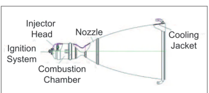
(Sutton, 2001). The thrust chamber is the main part of a rocket engine (Sutton, 2001). It is usually formed by an injector head, a combustion chamber, a nozzle, a cooling jacket, and an ignition system according to Fig. 1.
Nozzle Injector
Head Cooling
Jacket
Combustion Chamber Ignition
System
Figure 1. Thrust chamber.
The injector head consists of injectors distributed along the surface of a plate placed at the inlet of the combustion chamber and a set of ducts that guarantee a uniform distribution of propellants. The injectors are the key elements of the thrust chamber because they determine the behavior of propellants in the combustion chamber. It injects and atomizes the propellants into the combustion
chamber, mixing them homogeneously and in well deined ratios of fuel and oxidizer, before it is vaporized
and quickly ignited.
The injectors are classiied as centrifugal or jet. They can be
monopropellant or bipropellant (in case of bipropellants, for a better homogenization of the mixture) and can be used as a coaxial centrifugal injector.
The combustion chamber is the part of thrust chamber
in which the combustion of propellants occurs at high
pressure and temperature. The process of combustion can be characterized in three zones (Kessaev, 2006): 1)
gasiication zone (warming-up, evaporation), 2) burning
zone, and 3) combustion product mixing zone. Internal cooling of the combustion chamber is made to protect
the inner shell from contact with the high temperature gases. They can be of two types: by wall layer, which is constituted by a low of combustion products with lower burning temperature along the wall; and a wall screen formed by the liquid fuel ilm.
The hot gases of combustion are accelerated from the stagnation to transonic velocity in the throat, reaching supersonic velocity in the exit of the nozzle (Barrère, 1960).
There are different types of nozzles, including conical, contoured, and ring nozzle. Conical nozzles are simple and relatively easy to manufacture but they are not the
most eficient ones in terms of thrust for a given length. The type of nozzle chosen in this work was the conical
one, due to simplicity and easiness to manufacture it.
The basic objective of the cooling jacket in a thrust
chamber is to prevent its walls from becoming too hot, and enable them to withstand the imposed thermal loads
weaker when temperature is increased. Cooling, thus, reduces the wall temperatures to an acceptable value
(Sutton, 2001). The regenerative cooling is carried out by a cooling jacket around the thrust chamber by circulating one of the liquid propellants through it before it is fed to the injector head.
The propellants are combined inside the combustion chamber
where they chemically react to form hot gases which are then
accelerated and ejected at high velocity through the nozzle
(Huzel and Huang, 1992; Kessaev, 2005).
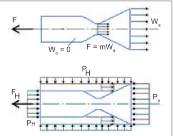
The equation of thrust in atmospheric conditions (Eq. 1),
as shown in Fig. 2, is given by:
FH = m.Wa + Aa(Pa- PH) (1) Where Aa is the outlet area of the nozzle, P
a is the outlet static pressure of the nozzle and P
H is the ambient pressure.
This equation shows a balance between the created forces
due to the mass ejected by the rocket and the force due to the effects of pressure at the exit plane of the nozzle. In space applications, the ambient pressure is considered zero (vacuum).
Isp= 2kRTch (k-1)
1-Pa Pch £ ¤ ² ¥¦´
k-1 k ³ ³ ³ µ µ µ (3)
Equation 2 also shows that the Isp decreases with the increase
of atmospheric pressure and the same is directly proportional
to the thrust. Equation 3 shows that when the LRE is operating in vacuum, with the value of Pa tending to zero, the value of
Isp is independent on the combustion chamber pressure.
The characteristic velocity, C*, is a igure of thermochemical merit for a particular propellant and may
be considered as an indicative of the combustion eficiency. It can be calculated in two ways: experimentally through
the chamber pressure measurement (Pch), critical area section (Acr) and mass low rate ( m) according to Eq. 4 and from the thermodynamics properties of propellants used according to Eq. 5:
C*
=PchAcr
m (4) C* = RT ch 2 k+1 £ ¤² ¥ ¦´ 1 k -1 . 2k k+1
(5)
Where:R: gas constant in (J/Kg.K);
T
ch: temperature of combustion gases in chamber in (K); k: adiabatic exponent.
The value of C* empirically calculated considers a loss due to the friction and the movement of the combustion gases in the throat of the nozzle. This loss depends directly
on the proile of the nozzle.
METHODOLOGY OF LABORATORY WORK
The experimental test stand was initially designed to carry out iring and cold low tests of liquid propellant rocket
engines using a pressurized propellant feed system. The
LRE will use ethyl alcohol (C2H5OH) as fuel and gaseous oxygen as oxidizer.
The choice of the propellants (ethyl alcohol and
gaseous oxygen) was made based on requirements for low cost, ease of acquisition, and non toxic
F
W o = 0
F = mW a W a F H P H PH P a
Figure 2. Thrust in atmospheric conditions.
The speciic impulse Isp is the main performance
measurement of an LRE. It is used as a base for comparison among propellants, combinations of propellants, and overall performance of LREs. The Isp can be calculated in
two ways: experimentally, measuring the thrust (F) and the mass low rate ( m) of the propellant according to Eq. 2 and from the thermodynamics properties of the propellants for a given expansion ratio Pa/Pch, according to Eq. 3:
Isp = F F
m=
Aa(Pa-PH) m p = Fm
combustion product. Gaseous oxygen can be readily and inexpensively obtained in pressurized cylinder in almost all communities because it is used in
oxy-acetylene welding. With reasonable precaution, it is
safe to handle and for rocket test stand use. The alcohol is readily available in some communities. Safety
precautions are already known by the most responsible personnel due to wide use of the fuel in internal combustion engines for automobiles and other power machines. The combustion chamber will be water
cooled. The pressurization of the fuel tank and the pilot
lines that feed the pressure regulators, as well as the purging of the fuel lines, will be made with gaseous
nitrogen (GN2) from pressurized cylinders at 200 bar.
The test stand allows tests of rocket engines in different
regimes of operation by enabling the variation of parameters
such as chamber pressure, mass low rate, and iring time.
It provides measurements of several physical variables
associated with these regimes. The test stand will be controlled automatically by a computer (PC) that will enable real-time measurements during the rocket engine iring, allowing remote control and more safety to the operator.
The tests will be carried out in four different regimes of operation with constant mixture ratio (km) – ratio between the mass low rate of oxidizer and mass low rate of fuel. The change of regimes will be obtained by the variation of propellant feed line pressures, mass low rates, and chamber pressures. The iring time will also be varied, limited only
by the size of the fuel and oxidizer tanks. The number of operational regimes can be extended calibrating the system
with additional values of feed line and chamber pressures. The tests will be conducted sequentially according to a pre-deined operational regime. The system will also allow
the user to choose one unique regime of operation among
four available options. Figure 3 shows a test with four
regimes of operation carried out sequentially, and Fig. 4 illustrates an example of choice for an only regime that can be sometimes replied to survey statistics.
Figure 3. Sequential regimes.
Time (s)
T
rust (Kg)
120
100
80
60
40
20
0
0 5 10 15 20 25 30 35 40 45
Figure 4. Representation of one unique regime.
Time (s)
T
rust (Kg)
0 0 5 10 15 20 25 30 35 40 45
1 2 3 4 5 6 7 8 9 10
The control system will basically work in three different conditions: set up, operation, and shut down;
operation condition is subdivided into starting, test,
wait and finishing.
The test is initiated with actions of opening and closing synchronized feed line valves, irstly to ignite the
gas-dynamic igniter and then to provide the conditions to
start the engine iring. During engine iring, the mixture
ratio is kept constant by controlling the propellant
line pressures with automatic pressure regulators (PID system). Initially, the pressures related to mass low
rates (fuel and oxidizer) are obtained by calculations but
veriied experimentally.
DEVELOPMENT OF TEST STAND INSTALLATIONS
The main requirements of the test stand and engine developed are:
a) propellants are ethyl alcohol and oxygen gas;
b) capacity of generating a 50 to 100 kgf range of thrust;
c) constant mixture ratio (km) for maximum speciic impulse;
d) four regimes of operation with chamber pressure of 8, 10, 12 and 15 bar;
e) maximum admissible pressure of combustion
chamber: 20 bar;
f) duration of each regime of operation equal to 10
seconds;
h) gas dynamic igniter for multiple ignitions;
i) water-cooled jacket;
j) automated data acquisition and control system;
k) acquisition of temperature values, pressure, mass
low rate and thrust;
l) system safety is automatic, safety routine program
is to ensure that safety, consistent with mission
requirements, is designed into systems, subsystems, equipment, facilities, and their interfaces.
Considering the mixture ratio km equal 1.6 to maximize
speciic impulse, the values for mass low rates of
propellants of the combustion chamber and their respective
thrusts for four operational regimes were calculated and the results are shown in Table 1.
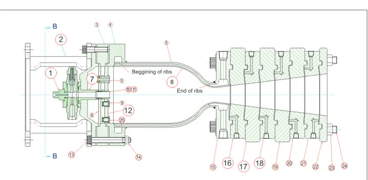
Figure 5 provides an AutoCAD drawing in cross section
of a thrust chamber, detailing the ignition system (detail
1) and the mechanical interface of the engine with the frame of the test stand (detail 2). The injector head will be
made of stainless steel except the base plate (detail 12) and
igniter ducts (detail 7), which will be made of copper. The combustion chamber will be made of stainless steel. On the inner shell (detail 6), there will be milling ribs that begin in the cylindrical part and inish in the throat; the cooling jacket is constituted of a double wall shell, without ribs.
The inlet and outlet of the cooling system can also be seen in details 15 and 4. The nozzle is segmented in parts that
can be removed during the laboratory work as coniguration makes it possible to verify the inluence of expansion ratio
on thrust. Consequently, three conditions of expansion in the nozzle can be tested: under expanded, over expanded,
and adapted. In the planned work, the tests to determine LRE thrust characteristics will be carried out only in three
segments (details 16, 17 and 18 of Fig. 5) corresponding to an adapted nozzle at sea level.
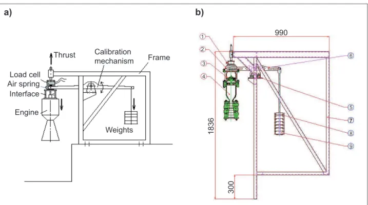
The thrust measurement system is part of the test stand
frame and it is constituted of an interface support that ixes the engine in the frame, a compression load cell (which
measures the thrust force) and a calibration mechanism, as
the system shown schematically in Fig. 6. Strain gages, load cell, were placed on the beam to convert strain to a voltage
proportional to the thrust force. The calibration is easily
effected by adding weights. In order to obtain a proper zero
reading for all thrust measurements, it is necessary that the
whole measurement system be pre-stressed with a pre-load
of 5-10% of the expected thrust. The frame of the test bench
is constituted of the parts shown in Fig 6.
Regimes Pch
(bar) mO (kg/s)
mf (kg/s)
FH (kgf)
1º 8 0.200 0.125 56.05
2º 10 0.250 0.157 70.22
3º 12 0.301 0.188 84.43
4º 15 0.376 0.235 105.78
Table 1. Pressures in the combustion chamber (Pch), mass low rates (mO,
mf) and thrust (FH) values.
Figure 5. General drawing of longitudinal cross section thrust chamber.
1 2
7
12
16 17 18
5
5 4
3
10 11
Beggining of ribs
End of ribs
9
8
25
13 B B
14
A structural analysis of the test stand frame, using the inite element method, was carried out to evaluate the linear static
behavior and modal to steel ASTM-A36. The main results of
the analysis are listed below and Fig. 7 shows the mesh and Von Mises stress. The values of stress are below the admissible stress in the analyzed models and no problem was found in the screws of the frame and in the bearings of the load cell. Table 2 shows the natural frequency of the frame test stand.
Figure 6. Thrust measurement system: (a) lateral view of scheme test stand and (b) design in CAD. 1: load cell (thrust force measurement); 2: air spring (pneumatic spring); 3: support to ix the engine in the frame; 4: rocket engine; 5: damper; 6: balance beam; 7: body; 8 and 9: counterweights (5 and 10 kg).
Engine Load cell
Thrust Calibration
mechanism Frame
Weights Interface
Air spring
990
1836
300
1
2
3
4
5 6
7
8
9
a)
b)
Frequency number Frequency (seconds)
1 0.7136914E-01
2 0.4997758E-01
3 0.3089837E-01
4 0.2763159E-01
5 0.1987037E-01
Table 2. Natural frequency.
The feed system is constituted of an hydropneumatic installation illustrated in Fig. 8, composed of piping lines, a
series of valves, provisions for illing and removing (draining and lushing) the liquid propellants, and control devices to initiate, stop, and regulate their low and operation.
GOX passes from a stored cylinder through a pressure
regulator, where its pressure is reduced and feeds the engine when electric valves are opened. Part of the
GOX is also used in the ignition unit. GN2 from a stored cylinder is reduced by the pressure regulator and pressurizes the fuel tank to feed the engine. The
scheme also shows the cooling water inlet in the throat
region of the engine and the exit from the mixing head.
Figure 8 also shows temperature, pressure, and thrust
measurement cell load sensors.
The layout of the test complex is shown in Fig. 9, which gives an overview of the arrangement, equipment of control and data acquisition system. The interface between the test stand and the control room will be carried out by
signal transmission cables represented by the black dotted
line in Fig. 9. The propellant and pressurization gas will
be located in three separated bays, and the engine rocket
will be installed in the frame of test stand. Figure 9 also shows the control room which not only serves to protect
test personnel from a possible combustion chamber or tank explosion, but also contains the equipment controlling for test operation and data acquisition equipment.
According to Fig. 7, the maximum stress was obtained where the engine was ixed. The results to stress,
displacement, and values to steel ASTM-A36 are:
• admissible stress=150 MPa;
• maximum vertical displacement=0.45 mm;
• maximum stress (Von Mises)=83.9 MPa;
Figure 7. Results – (a) Mesh and (b) Stress (Von Mises).
a)
b)
Von Mises 8.3925E + 007 7.3434E + 007 6.2944E + 007 5.2453E + 007 4.1963E + 007 3.1472E + 007 2.0901E + 007 1.0491E + 007 0.000000000
xyz
Figure 8. Hydropneumatic scheme. RP(n): pressure regulator (n=1,2,3,4,5), T(n): thermocouple (n=1,2,3,4,5), VA(n): relief valve (n=1,2,3,4,5,6), VM(n): manual valve (n=1,2,3,...,14), VS(n): solenoid valve (n = 1,2,3,...,10), MV(n): lowmeter (n=1,2,3,4).
F2 VM7 Water Inlet GOX
VM9 VS7 VM12
VM13
RP4 PG5 PG7
VA5
PG6 T4
MV4 VM14
RA2 VS9 VA6
RP5 Ignition Unit
VM11
VS10 P10
P8 T3
VM10
MV2
VS8
MV3 VM8
P7
P6
P15 P16
P17 P14
P13 P12
P11 P4
igniter
C
o
m
b
u
st
io
n
C
h
a
m
b
e
r
P2 VR1
A
1 2 3 4 5 6 7 8 9 10
B
C
D
E
F
G
H
VS4 MV1
F1 T5 VM4
VR2
P5 P9 LC1
VS5 VM6 PG3
GN 2 VM1
VS1 VM2
VA3
VA2
VS3 P1 VS2 VM3
RP1 PG2 VA1
VA4 PG4
PG1
RP2 RP3
MN1 VM15
VM5 RA1
Fuel tank
P3
T1 T2
The control and acquisition system in use in the test stand is composed by the elements presented in the system architecture (Fig. 10). The pressure transducers (PT), mass
low rate (FT), strain or thrust (ST) and temperature (TT), shown in Fig. 10, are sensitive elements that convert the
physical phenomena of the experiment in electrical signal
that will be conditioned and later analyzed. The signals will be conditioned and processed in the PXI platforms
of instrumentation for measurement and automation of National Instruments.
Figure 9. Layout of test complex. BAY 1
(FUEL AND WATER)
BAY 2
(PRESSURIZATION GAS)
BAY 3 (GAS OXYGEN)
INSTRUMENTATION ROOM
TEST STAND
CONTROL AND DAQ LINES
IGNITION SYSTEM
50 m
CONTROL ROOM
FUEL (ALCOHOL) PRESSURIZATION GAS (GN2) GAS OXYGEN (GOX)
WATER
In Fig. 10, item (1) is a controller system only for temperature data, (2) is the temperature peripheral module, (3) is a controller for other data acquisition and
Figure 10. Data acquisition system architecture. EXPERIMENT INSTR. ROOM
CONTROL ROOM
SWITCH
Ethemet TB
HMI
RACK PXI 2
3 4 5 PT
FT ST TT
ACTUATORS
REGULATORS
BLI ACTUAT. TB
RACK PXI 1 1
BLI SENSORS
2
PT: pressure transducers; FT: mass low rate; ST: strain or thrust; TT: temperature; HMI: human-machine interface. 1: controller system only for temperature data; 2: temperature peripheral module; 3: controller for other data acquisition and control; 4 and 5: pressure regulator.
control and (4) is the pressure regulator. The interface
with user or human-machine interface (HMI) is carried
out by means of a personal computer connected by
ethernet and a software that, in this case, will be the LabVIEW program. The control will be carried out
through the opening and closing of the solenoid valves, also commanded by PXI racks.
It will be possible through the automatic system to
control the pressure in the lines of fuel and oxidizer
to keep the mass low rate constant. It is done by a
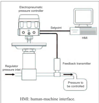
microcontroller-based device that implements a digital control algorithm (PID controller) to regulate pressure. PID controller involves three parameters of control: proportional, integral and derivative values that are
obtained by test. The weighted sum of these three
actions is outputted to a control element such as the
position of the control valve. Figure 11 shows a scheme
of control in pressure regulators using computer: the
user is responsible for ixing a setpoint value to control
the pressure.
Figure 11. Control in regulators by computer to keep the pressure constant.
Electropneumatic pressure controller
Setpoint
HMI
Feedback transmitter Regulator
pressure inlet
Pressure to be controlled
HMI: human-machine interface.
METHODOLY AND DEVELOPMENT OF PROGRAM
The program developed for test stand control and data
acquisition for LRE test uses the software LabVIEW
because of its user interface and the readable, scalable and maintainable algorithm. The development of this
Design
In this phase, the interface between the user and the available infrastructure was described to meet the functioning of
the LRE and installation of the hydropneumatic scheme,
as shown in Fig. 8.
Building
In this phase, there was the interpretation of performed
requirements resulting in the development of the
LabVIEW codiication. All codiication sequence was made in a modular and scalable way, with comments inserted in the program. Figures 14, 15 and 16 show
some LabVIEW screens developed to control the test stand.
Figure 14 shows the irst screen of the program with its guides. This screen, called “Gravação”, allows the
user:
• to choose the name and the folder where the acquired test data will be saved;
• to monitor and save the generated sensor data;
• to inish the check of sensors when they are being monitored;
• to determine the time of countdown of the test.
The guide screen “Canais” allows the user to choose the type of coniguration and adjust the data channels for the valves or keep the default. Figure 15 shows the guide screen
“Seleção das Pressões”, displaying chamber pressures available to the test stand.
Finally, Fig. 16 shows the guide screen “Ensaio”, where the user can perform and observe other options such as an elapsed time clock, a clock with countdown
to the test, and the pressures of the combustion chamber carried out at the moment of the test. There is
one visual alert when the internal pressure during tests
exceeds the pre-established values.
Veriication
This phase enables the user to identify and correct errors
in the program. The following veriication tests were
performed:
a) software function test, in which one can verify if all requirements were contemplated in the codiication;
Figure 12. Phases of the methodology for the program development.
Methodology for the development
of program
9Analysys
9Design
9Building
9Verification
9Implantation
Analysis
In this phase, the investigation of the necessary data for
the understanding of the design requirements was done. Hydropneumatic scheme was planned and developed with
the schedule of all its activities from activation through
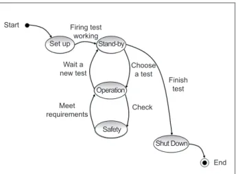
shutdown of the test stand. Based on the hydropneumatic scheme shown in Fig. 8, the state machine was prepared, with the purpose of supplying and focusing on the development of the program (Shaw, 2003). Figure 13 shows the state machine of the hydropneumatic scheme
of test stand.
Start
Set up Stand-by
Operation
Safety
Shut Down Firing test
working
Wait a new test
Meet
requirements Check
Finish test
End Choose
a test
Figure 13. Test stand state diagram.
According to Fig. 13, during the set up phase, the test stand is checked, i.e, valves, pressure regulators, gas
lines and so on, until the stand-by state, when it will be ready to choose a test. During the test stand work, safety
routines are used to monitor some system parameters like pressure and temperature, in order to avoid incidents due to super heating or pressure higher than
the one speciied in the design. The safety routines are
programmed to perform determined actions of system protection by executing routines like closing of valves,
Figure 14. Initial screen of interface with user.
Figure 16. Guide screen “Ensaio”.
b) black box testing of the functionality of software and its interaction with the user;
c) white box testing, in which the source code was tested
in detail and all transitions of the program demands
were verii ed;
d) integration testing, in which the architecture of the program and its communication with external interfaces were tested.
Description of test
The objective of test was to simulate the parameters through the computer in ambient Windows using the
National Instruments Data Acquisition System. In order to simulate the opening and closing of the solenoid valves, a schematic panel of the hydropneumatic
system was used with leds representing the state of the
valves. These leds turn on/turn off at a determined time, representing the open/close state of the solenoid valves during the tests. To verify the data acquisition system,
a device called DAQ-Acessory was used to supply a square wave as analogical input and was displayed and
stored by program.
Implantation
In this phase, it was dei ned the position of the control hardware on the test stand inside the control room in the
LPL (Fig. 9). The responsibility level of each operator
during the test is in accordance with the standards of IAE.
This standard requires an IAE qualii ed professional to be
the test supervisor and manage the step operations of the test stand.
CONCLUSION
This work presented the specii cation of an experimental i ring test stand for a LRE and the apparatus to its development in order to carry out the laboratory work.
The design of a hydropneumatic scheme and a LRE led to the development of a program to control and acquire data,
providing conditions to the engine work in agreement with parameters of design.
All the phases of this project were done with two major aims: the excellence required in the i eld of Space
Engineering and the state of the art of several Engineering
i elds like electricity, mechanics, thermodynamic, heat
higher knowledge and aggregate value to the development
and investigation of LREs.
ACKNOWLEDGEMENTS
This work was supported in part by the Institute of
Aeronautics and Space (IAE) and Aeronautics Institute of Technology (ITA).
REFERENCES
Alves, W.A.F., 2008, “Development of experimental iring
test stand to study the rocket engine thrust characteristics”, Masters Thesis, Aeronautics Institute of Technology, São José dos Campos, 198f.
Andrade, E., 2008, “Graphical Programming applied
to the control iring test stand of liquid rocket engine”.
Masters Thesis, Aeronautics Institute of Technology, São José dos Campos, 133f.
Barrère, M., et al., 1960, “Rocket propulsion”, Elsevier Publishing Company, London.
Brazilian Space Agency, 2005, “National Plan of Space Activities. PNAE 2005-2014”. Brasília, DF, 44p.
Huzel, D.K., Huang, D.H., 1992, “Modern engineering for design of Liquid Propellant Rocket Engines”. AIAA, Washington.
Kessaev, K.V., 2006, “Theory and Calculation of Liquid Rocket Engine”, In: “Fundamental Course in Engine Course Design”, ITA/MAI, São José dos Campos.
Kessaev, K.V., 2005, “Introduction to Liquid Rocket Engine Design”, In: “Fundamental Course in LRE Introduction”, CTA/ITA, São José dos Campos.
Shaw, A.C., 2003, “Systems and software in real time”,
Porto Alegre: Bookman.
Sutton, G.P., Biblarz, O., 2001, “Rocket propulsion