Clínica de Ritmologia Cardíaca do Hospital Beneficência Portuguesa de São Paulo Mailing address: José Tarcísio M. de Vasconcelos – Rua Maestro Cardim, 1041 01323-001 – São Paulo, SP – Brazil - E-mail: [email protected]
José Tarcísio Medeiros de Vasconcelos, Eduardo Rodrigues Bento Costa, Silas dos Santos Galvão Filho, Cecília Monteiro Boya Barcellos, Jaime Giovany Arnez Maldonado
São Paulo, SP - Brazil
Block of the Mitral-pulmonary Isthmus During Ablation of a
Single Left-sided Accessory Pathway Causing Different
Patterns of Retrograde Atrial Activation
The case of a 16-year-old patient with atrioventricu-lar tachycardia caused by a single left anterolateral ac-cessory pathway is reported. When the patient underwent radiofrequency ablation, a lesion on the mitral annulus lateral wall produced changes in the retrograde atrial activation pattern determined by that pathway; changes ranged from a delay in depolarization of the annulus pos-terior portions to full left atrium counterclockwise activa-tion. Such phenomena were probably caused by a block in the isthmus between the annulus and the lower left pulmo-nary vein ostium. This case illustrates the importance of the mitral-pulmonary isthmus in the process of left atrium activation, an alert to changes induced by its unintentio-nal block during accessory pathway ablation.
Recent observations1,2 have pointed out the role of
the isthmus between the lower left pulmonary vein and the mitral annulus in determining features of retrograde atrial activation, during ablation of a left lateral accessory pathway.
This article reports a case of atrioventricular tachycar-dia generated by a single left anterolateral accessory path-way with exclusive retrograde conduction where radiofre-quency current, applied to the lateral wall of the mitral annu-lus, produced diverse patterns of retrograde atrial activation. Potential electrophysiologic mechanisms at the root of observed peculiarities are discussed.
Case report
A 16-year-old female patient who had experienced re-current supraventricular tachycardia since the age of 6
un-derwent invasive electrophysiologic examination and ra-diofrequency (RF) catheter ablation.
The procedure was performed with the patient sedated with intravenous fentanyl and midazolam. Through a punc-ture in the right femoral vein, three 6-French quadripolar ca-theters with 5-mm electrode spacing (ResponseTM, DAIG,
Inc., Minnetonka, MN, USA) were positioned at the right cardiac chambers to record electric potentials of the right ventricle apex, the His bundle, and the upper right atrium. By means of right subclavian vein puncture, a 6-French oc-tapolar catheter with electrode spacing of 5-mm (Bard Elec-trophysiology, Billerica, MA, USA) was introduced into the coronary sinus. This catheter was advanced up to the late-ral region of the mitlate-ral annulus. All recordings were digitized, continuously displayed, and recorded on an electrophy-siology recording system (SP32, TEB, São Paulo, Brazil). The signals were filtered into values between 30 and 500 Hz. An accessory pathway was noticed on the free wall of the mitral annulus, showing exclusive retrograde conduc-tion, and episodes of reciprocal atrioventricular tachycardia were easily induced. Having detected this, an ablation 7-French 4-mm tip catheter (LivewireTM, DAIG, Inc.,
Minne-tonka, MN, USA) was introduced through a puncture in the right femoral artery, to explore the mitral annulus by the re-trograde transaortic route.
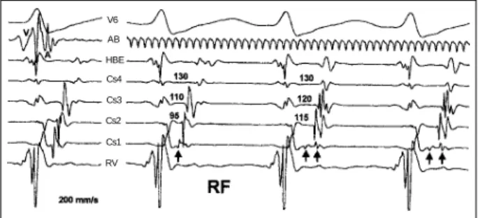
Such mapping, initially performed during tachycardia, facilitated the discovery of a site of great prematurity in atrial electrograms on the lateral portion of the mitral annulus. RF current applied to that point was followed by atrial electro-gram fragmentation into 2 components, as detected by the distal coronary sinus lead and, simultaneously, by changes in the left atrial activation sequence, while tachycardia cycle length remained unchanged (fig. 1). The ventriculoatrial in-terval, as measured up to the first component of the frag-mented atrial electrogram, has not undergone changes, but a delay occurred in atrial activation in portions corresponding to the posterior annulus region. Inability to stop tachycardia led to the premature interruption of RF application.
pathway, performed during ventricular pacing, again a point of great atrial prematurity was noticed, but adjacent to the one initially reached. A new RF application induced the same phenomenon previously observed, with fragmenta-tion on atrial electrograms of the distal coronary sinus into 2 components, and similar changes in the atrial activation sequence.
After this application, tachycardia continued to be in-duced with the same original cycle, showing either a double potential recorded at the distal coronary sinus or a sequen-ce of counterclockwise atrial activation. Premature ventri-cular depolarization, introduced when the His bundle was refractory, confirmed the participation of an accessory pathway in the tachycardia mechanism.
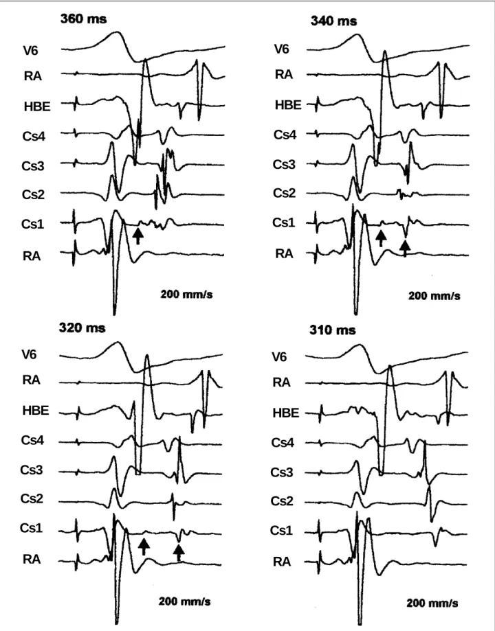
Incremental pacing of the left ventricle was followed by a gradual change in the atrial activation sequence, which started from a typical eccentric pattern, changed to an inter-mediate pattern with clear fragmentation of distal coronary sinus atrial electrograms, and reached a fully counter-clockwise pattern (fig. 2). The pacing interruption at this moment was followed by tachycardia induction with coun-terclockwise atrial activation sequences. The 2 initial longer tachycardia cycles showed the intermediate atrial activa-tion pattern and double atrial electrograms recorded by the distal coronary sinus lead, the change to the counter-clockwise pattern being correlated to a shortening of the ta-chycardia cycle (fig. 3). Interestingly, further mapping of the mitral annulus during counterclockwise tachycardia has shown that the earliest site of atrial activation was on the annulus anterolateral region, above both the distal coro-nary sinus lead and the previously ablated site (fig. 4). The procedure ended without therapeutic success.
former procedure, was confirmed as the same, on the left an-terolateral portion of the mitral annulus. One sole RF application at this point under ventricular pacing was imme-diately followed by normalization of the retrograde atrial activation sequence. Procedure success was confirmed by failure to induce tachycardia, by the physiological retrogra-de conduction features when using incremental and prema-ture ventricular stimulation, and by induction of atrioventri-cular dissociation using adenosine during ventriatrioventri-cular pa-cing. The patient has been asymptomatic throughout 6 months of follow-up.
Discussion
Atrioventricular tachycardia, in the reported case, was caused by a single accessory pathway, situated in the anterolateral region of the mitral annulus, where a lesion ge-nerated by RF current on a lateral portion of the annulus in-duced twofold changes in the atrial activation pattern.
A change in the atrial activation sequence, produced by an RF lesion during atrioventricular tachycardia, usually suggests coexistence of 2 or more accessory pathways involved in its mechanism. In the reported case, however, such a possibility was discarded in view of the following findings. 1) Regardless of the differences in the induced tachycardia atrial activation sequences, their cycle length remained the same. 2) The presence of 2 or more pathways taking part in the atrial activation process does not justify the emergence of a double potential at the distal coronary sinus level after RF ablation, as was observed. Under such circumstances, it might be inferred that the injury provoked slower conduction at a lateral pathway, thus delaying activa-tion of the left atrium posterior poractiva-tions. However, if the atrium were being activated simultaneously (or nearly so) from 2 or more points, the activation delay from 1 of these points, would only produce a displacement in the collision site of the impulses propagated from them; it would defini-tively not justify the double potential, which can only be ex-plained, both clinically and experimentally, in areas where ei-ther slow conduction or a conduction block occurs3,4. 3) At
the moments tachycardia showed double atrial potential at the distal coronary sinus, the ventriculoatrial conduction ti-me (counted until the first component of the atrial elec-trogram) was identical to the one observed in the original pattern (fig. 1). This shows that not the origin, but only form of impulse propagation along the atrial myocardium was changed. 4) In spite of failure of the first ablation at-tempt–3 forms of atrial activation having persisted during ventricular pacing–success was obtained during the second ablation session, by aiming at a single point.
Another possible explanation for the diverse retrogra-de atrial activation patterns observed is a Y-shaped accessory pathway having 1 ventricular insertion and 2 Fig. 1 - Tracings obtained during supraventricular tachycardia. Pictured are ECG
recordings from surface lead V6, ablation catheter (AB), His bundle electrogram (HBE), proximal coronary sinus (Cs4), coronary sinus 3 (Cs3), coronary sinus 2 (Cs2), distal coronary sinus (Cs1), right ventricle (RV). On the left are the electrograms obtained before application of radiofrequency. The ablation catheter is positioned on the lateral side of the mitral annulus; note the great prematurity of the atrial electrogram. The coronary sinus catheter is introduced up to the lateral portion of the annulus. On the right are the electrograms obtained during application of radiofrequency. Note a great reduction in Cs1 atrial electrogram amplitude (arrow), and a local fragmentation into 2 potentials (double arrow), with simultaneous activation delay of the posterior region of the annulus, represented by Cs2 and Cs3. The tachycardia cycle length does not change and the ventriculoatrial conduction time of the left posteroseptal region, represented by Cs4, remains fixed.
AB HBE Cs4 Cs3 Cs2 Cs1 V6
Fig. 2 - Tracings obtained during incremental pacing of the left ventricle. Shown Pictured are ECG recordings from surface lead V6, right atrium (RA), His bundle electrogram (HBE), proximal coronary sinus (Cs4), coronary sinus 3 (Cs3), coronary sinus 2 (Cs2), distal coronary sinus (Cs1), and right ventricle (RV). Different pacing cycle lengths are presented, from left to right and from top bottom, respectively, 360, 340, 320, 310 ms. Note a the fragmentation of the Cs1 atrial electrogram into 2 potentials, a progressive change in the atrial activation pattern and progressive activation delay of the left posterior region, represented by Cs2 and Cs3 electrograms, up to the installation of a counterclockwise sequence. No significant variations exist in the ventriculoatrial conduction time measured at the proximal coronary sinus (Cs4) during the entire process. The ventriculoatrial conduction time measured up to the Cs1 atrial electrogram first component remains stable prior to its disappearance, when an inversion occurs in the atrial activation pattern. Pacing interruption at this moment led to atrioventricular tachycardia induction with a counterclockwise atrial activation sequence (see fig. 3).
Cs4
Cs3
Cs2
Cs1
HBE
RA
V6
RA
Cs4
Cs3
Cs2
Cs1
HBE
RA
V6
RA
Cs4
Cs3
Cs2
Cs1
HBE
RA
V6
RA
Cs4
Cs3
Cs2
Cs1
HBE
RA
V6
tium to an approximate 4-cm extension5 . These muscle
bun-dles are linked to the left atrium wall by equally muscular connections wrapped by adipose tissue. Such structure may in theory function as an electrically active system that contributes to the left atrium activation process. In the pre-sent case, a pathway could be assumed to be linked both to that musculature cuff and to the left atrium wall. An RF lesion at the pathway portion that was connected to the left atrium wall might make the atrium retrograde activation process pre-ferentially, or fully, dependent on the coronary sinus mus-cles. The impulse, propagating from the accessory pathway along these muscle bundles, should in this case activate the left atrium through their connections, thus modifying its ac-tivation pattern. A block in these connections could lead the impulse to propagate along the coronary sinus muscles until its ostium and, from that point, activate the left atrium in a co-unterclockwise pattern. These hypotheses might explain the present findings, but a series of arguments dismiss them: 1) Supposing that left atrium activation depended both di-rectly on the accessory pathway and on the coronary sinus muscles attached to the pathway, an RF lesion-induced blo-ck in the atrial branch would indeed change the atrial acti-vation sequence, but would not explain the double atrial po-tential, as observed. A partial lesion on this branch would modify the atrial activation pattern by displacing the colli-sion point of impulses coming from both activation sources, but would not, again, justify the double potential found. It might be argued that the first component of the observed double atrial electrogram corresponded to the potential of a connection of the coronary sinus muscles to the atrial wall; if this were true, then the slower conduction through the atrial branch would generate preferential activation starting from that muscular connection, with a longer ventricular-atrial conduction time, thus explaining the delay in depola-rization of left atrium posterior portions; however, this should also entail changes in the tachycardia cycle, which were not observed, as shown in figure 1. 2) The counter-clockwise-activated tachycardia could be explained, as dis-cussed above, by the propagation of an impulse starting from the accessory pathway and reaching the coronary sinus ostium through the musculature cuff, thus provoking a lateral-bound left atrium depolarization. But this hypo-thesis is discarded due to the fact that, during the observed tachycardia, atrial activation of anterior septal portions preceded that of posterior portions (fig. 3). In addition, mitral annulus exploration allowed identification of the site of earliest atrial activation in the mitral annulus anterolateral region (above the lesion point), which is not compatible with such a model (fig. 4). 3) The RF lesions responsible for the changes in the left atrial activation pattern were generated on the lateral portion of the mitral annulus, while the ac-cessory pathway was effectively found to be on the left anterolateral region.
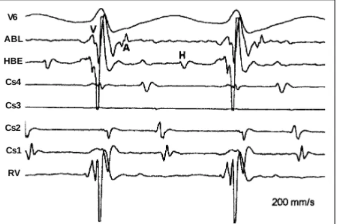
atrial myocardium insertions. Following this hypothesis though to explain findings, one would have to assume that 1 of these insertions was connected to the mitral annulus la-teral portion (RF lesion site) and the other to the anterosep-tal region. An RF lesion at the former would cause the entire atrial activation process to occur through the latter, genera-ting a fully counterclockwise atrial activation sequence. But, considering the distance between those 2 points, it is highly unlikely that a Y-shaped pathway could connect such faraway points. Furthermore, this would not explain the other atrial activation pattern observed, that is, with double potential at the distal coronary sinus level. Slower conduction at the lateral pathway insertion, provoked by Fig. 4 - Tracings obtained on exploration of the mitral annulus during tachycardia with a counterclockwise atrial activation sequence. Pictured are ECG recordings from surface lead V6, the ablation catheter (ABL), His bundle electrogram (HBE), proximal coronary sinus (Cs4), coronary sinus 3 (Cs3), coronary sinus 2 (Cs2), distal coronary sinus (Cs1), and the right ventricle (RV). The ablation catheter is placed on the mitral annulus anterolateral region, above the level of both the distal coronary sinus electrodes and the previous RF-lesion point. In spite of the counterclockwise atrial activation pattern along the coronary sinus through the lateral wall, a marked prematurity can be observed in atrial electrograms recorded by the ablation catheter.
ABL
Cs4
Cs3
Cs2
Cs1 V6
RV HBE
Fig. 3 - Atrioventricular tachycardia induction after left ventricular incremental pacing. Pictured are ECG recordings from surface lead V6, right atrium (RA), His bundle electrogram (HBE), proximal coronary sinus (Cs4), coronary sinus 3 (Cs3), coronary sinus 2 (Cs2), distal coronary sinus (Cs1), and right ventricle (RV). The asterisks (*) indicate electrical artifacts. The first and second complexes correspond to the last paced beats (S); note the counterclockwise pattern of retrograde atrial activation. The 2 initial, longer, tachycardia cycles are followed by double atrial potentials at Cs1 (arrows), with a distinct atrial activation sequence. The tachycardia cycle length shortening, due to a nodal anterograde accommodation, is followed by a change in the atrial activation sequence to a concentric pattern. No significant changes occurred in the ventriculoatrial conduction time measured at the proximal coronary sinus.
Cs3 Cs2 Cs1
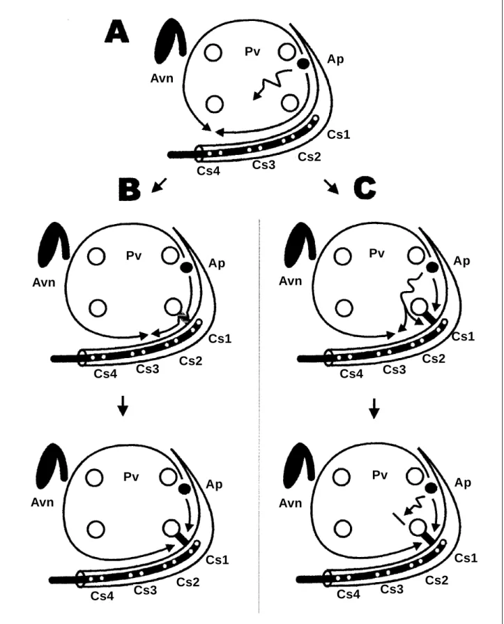
Fig. 5 - Diagram representing 2 possible mechanisms that might explain the observed phenomena (left atrium left anterior oblique view). Avn- atrioventricular node; Pv- pulmonary vein ostia; Ap- accessory pathway; Cs- coronary sinus leads as arranged in the initial procedure. Shown in A is the original atrial activation pattern during tachycardia, with im-pulse propagation in both clockwise and counterclockwise directions around the pulmonary vein ostia, colliding in the posteroseptal region. In B, an incomplete mitral-pulmonary isthmus block is RF-induced, slowing down the conduction and reducing the atrial tissue mass activated in a clockwise direction, bringing the collision zone to a posterior region of the annulus. Next, a complete isthmus block reaches the entire mitral annulus extension up to the lateral region to be activated by the wave propagated in a counterclockwise direction, generating a tachycardia with the same counterclockwise sequence. In C, pictured is an alternate way to explain the findings. The RF lesion causes a complete isthmus block; the annulus posterior portion is depolarized by a wave slowly propagated among the pulmonary veins, hence inducing sequential activation on both sides of the barrier and reducing the clockwise-activated atrial tissue mass. Next, a functional conduction block among the ostia causes the entire mitral annulus extension up to the lateral region to be activated by a counterclockwise wave, generating an equally counterclockwise tachycardia.
Avn
Avn
Avn
Avn
Avn
Pv
Ap
Cs1
Cs2
Cs3
Cs4
Pv
Ap
Cs1
Cs2
Cs3
Cs4
Pv
Ap
Cs1
Cs2
Cs3
Cs4
Pv
Ap
Cs1
Cs2
Cs3
Cs4
Pv
Ap
Cs1
Cs2
Cs3
of posteroseptal regions (as recorded by the proximal coro-nary sinus lead) preceded that of anteroseptal regions (as recorded by the His bundle lead). Such a finding could be in-dicative of a conduction block at the accessory pathway at that moment, when atrial activation became dependent on normal pathways, starting from the posterior portions of the atrioventricular node. However, pacing interruption led to in-ducing counterclockwise atrioventricular tachycardia, hence indicating that the conduction pattern previously observed was fully dependent on the accessory pathway (fig. 3).
By considering the closeness of the lateral region of the mitral annulus to the ostium of the left lower pulmonary vein, it can be inferred that the isthmus between these 2 points may play an essential role in the origin of the observed phenomena. In fact, other authors have made similar observations 1, 2.
The presence of a double atrial potential detected at the level of certain anatomical atrial barriers has been pointed out as indicative of slow conduction, or of a full-line block where each local electrogram component corresponds to sequen-tial depolarization of each side of the barrier 3,4. It can thus be
suggested that, in the case here reported, the lesion produ-ced by the RF current on the lateral region of the mitral annulus has provoked a conduction block of variable de-grees in the mitral-pulmonary isthmus. Such a block, if in-complete, would make the impulse to propagate from the atrial insertion of the accessory pathway along the coro-nary sinus in a clockwise sequence, but with slower con-duction at the isthmus barrier level, during either tachycardia or ventricular pacing, finally to collide at the annulus poste-rior region with the leading edge deriving from the anteposte-rior and septal depolarization. In the case of a complete block, the leading edge would not cross the isthmus barrier, and
indicate a rate-dependent block.
An alternate way of explaining the findings implies in-cluding into the hypothetical model the atrial myocardium portion located in-between the pulmonary veins. RF abla-tion at the mitral-pulmonary isthmus would have generated a full conduction block, making the impulse that propagates from the accessory pathway atrial insertion travel along an alternative route among the pulmonary veins, thus genera-ting sequential activation on both sides of the barrier. By considering the heterogeneity of atrial muscle-bundle ar-rangements in-between the pulmonary veins 6,7, it is logical
to assume the presence of nonuniform anisotropic conduc-tion in this region, which might produce variable, frequency-dependent changes in impulse propagation. The conduc-tion block in that tissue could generate a fully counterclock-wise atrial activation sequence along the coronary sinus, starting from the wave-edge that originates in the left atrium anterior and septal portions (fig. 5, sequence C).
Whatever the underlying mechanism that has produ-ced the observed diversity of atrial activation patterns, the reported case shows the importance of the region correspon-ding to the isthmus between the lower left pulmonary vein and the mitral annulus in determining the left atrium activation sequence. This seems to be a preferential route for impulse propagation, which gains relevance in situations that involve mapping accessory pathways on the mitral annulus free wall, and possibly primarily left atrial tachycardia. A change in the atrial activation pattern during an attempt to ablate a supposedly lateral left accessory pathway, especially when the catheter can not be made to advance in the coronary sinus to its full extension, should alert the electrophysiologist to the possibility of a mitral-pulmonary isthmus block.
References
1. Etheridge SP, Compton SJ, Klein RC. A left side isthmus? Conduction block following single RF lesion in human left atria. Circulation 1998; 17(suppl): A 2972.
2. Luria D, Nemec J, Friedman PA. Left atrial “isthmus” concept: pitfalls in lateral accessory pathway ablation. In: Ovsyshcher IE (ed.) Cardiac Arrhythmias and Device Therapy: Results and Perspectives for the New Century. Armonk, NY: Futura, 2000: 73-7.
3. Feld GK, Shahandeh-Rad F. Mechanisms of double potentials recorded during sustained atrial flutter in the canine right atrial chush-injury model. Circulation 1992; 86: 628-41.
4. Cosio FG, Arribas F, Barbero JM, Kallmeyer C, Goicolea A. Validation of double-spike electrograms as markers of conduction delay or block in atrial flutter. Am J Cardiol 1988; 61: 775-80.
5. Chauvin M, Shah DC, Haissaguerre M, Marcellin L, Brechenmacher C. The anato-mic basis of connections between the coronary sinus musculature and the left atrium in humans. Circulation 2000; 101: 647-52.
6. Cavalcanti JS, BiazzotoW, Tavares DS, et al. Anatomia funcional da junção entre o átrio esquerdo e as veias pulmonares. Arq Bras Cardiol 1994; 62: 239-41. 7. Nathan H, Eliakim M. The junction between the left atrium and the pulmonary