Author Manuscript
Published in final edited form as:
Clinical Biomechanics 62 (2019) 79–85
Doi:10.1016/j.clinbiomech.2019.01.005
Title:
BIOMECHANICAL ANALYSIS OF METACARPOPHALANGEAL JOINT
ARTHROPLASTY WITH METAL-POLYETHYLENE IMPLANT: AN IN-VITRO STUDY
Melo D, Completo A*, Nascimento A, Fonseca F
TEMA, Department of Mechanical Engineering, University of Aveiro, 3810-193 Aveiro, Portugal.
Abstract
Background
The most common implant options for the metacarpophalangeal joint arthroplasty include silicone, pyrocarbon and metal-polyethylene. A systematic review of outcomes of silicone and pyrocarbon implants was conducted; however, a similar exercise for metal-polyethylene implants revealed a scarcity of published results and lack of long-term follow-up studies. The aim of the present work is to test the hypothesis that the magnitude of metacarpophalangeal joint cyclic loads generates stress and strain behaviour, which leads to long-term reduced risk of metal-polyethyle ne component loosening.
Methods
This study was performed using synthetic metacarpals and proximal phalanges to experimenta lly predict the cortex strain behaviour for both intact and implanted states. Finite element models were developed to assess the structural behaviour of cancellous-bone and metal-polyethyle ne components; these models were validated by comparing cortex strains predictions against the measurements.
Findings
Cortex strains in the implanted metacarpophalangeal joint presented a significant reduction in relation to the intact joint; the exception was the dorsal side of the phalanx, which presents a significant strain increase. Cancellous-bone at proximal dorsal region of phalanx reveals a three to fourfold strain increase as compared to the intact condition.
The use of metal-polyethylene implant changes the strain behaviour of the metacarpophalangea l joint yielding the risk of cancellous-bone fatigue failure due to overload in proximal phalanx; this risk is more important than the risk of bone-resorption due to the strain-shielding effect. By limiting the loads magnitude over the joint after arthroplasty, it may contribute to the prevention of implant loosening.
Keywords: experimental strains; finite element model; MCP joint; stress-shielding; SR MCP System
Introduction
Arthritis in metacarpophalangeal (MCP) joint is relatively common, and it leads to disability, pain and disfigurement (Rizzo, 2011). When nonsurgical measures have been exhausted, the two primary surgical options involve implant arthroplasty or arthrodesis; however, given that MCP arthrodesis is poorly tolerated, implant arthroplasty remains the preferred surgical treatment (Adkinson and Chung, 2014; Linscheid, 2000). Currently, the most common implant options for the MCP joint arthroplasty include the silicone, pyrocarbon and the semi-constrained metal-polyethylene implants (Srnec et al, 2017; Aujla et al, 2017). Owing to the long history of MCP silicone implant arthroplasty, the main risks include the possibility for breakage and the stimulation of periprosthetic bone lysis due to wear (Drake and Segalman, 2010; Chung et al, 2009; Goldfarb and Stern, 2003; Trail et al, 2004; Schmidt et al, 1999). Very active patients that use their hands heavily may not be good candidates for silicone implants (Joyce, 2004). MCP pyrocarbon arthroplasty remains controversial with mixed outcomes (Aujla et al, 2017; Simpson-White and Chojnowski 2014; Drake and Segalman, 2010), the most common complications include subsidence, dislocation and loosening (Srnec et al, 2017; Dickson et al, 2015; Wall and Stern, 2013; Parker et al, 2007; Cook et al, 1999). Little, if anything, can be concluded about semi-constrained metal-polyethylene MCP implants, as there is lack of long term follow-up studies (Srnec et al, 2017; Aujla et al, 2017) and no reliable results have been published (Harris and Dias 2003). Also, studies on the structural biomechanics of metal-polyethylene MCP arthroplasty are very limited (Kung et al, 2003). Nevertheless, the concept of metal-polyethylene for MCP joint may provide the opportunity both to extend clinical indications and to provide more durable functional results (Murray, 2003). The metal-polyethylene SR MCP system (Stryker, MI, U.S.A.) attempts to re-establish the anatomic geometry of the metacarpal head, being suitable for use when
either the patient is in need of a revision failed MCP prosthesis; or the patient expects to submit his/her hands to loading situations, which preclude the use of an alternative implant in the painful osteoarthritic and post traumatic arthritic MCP joint (Operative technique SR MCP System, 2016). An appropriate in-vitro testing offers the potential to identify some long-term structural risks associated with this implant; therefore, contributing to somewhat filling the lack of clinica l outcomes of this implant design and assisting the improvement of the surgical decision-mak ing process. The hypothesis considered in this study is that the magnitude of MCP joint cyclic loads in daily hand functions generates stress, strain and initial stability behaviour, which yield reduced long-term risk of SR MCP system failure. Ideally, stress-strain values should be low enough to avoid exceeding fatigue levels of materials, but also, should not be below bone strain-shield ing inductive levels, which will lead to significant bone atrophy, ultimately resulting in impla nt loosening.
Methods
Five synthetic metacarpals and proximal phalanges bones were manufactured, considering that they were not commercially available (Figure 1). The metacarpals and phalanges structures were identical, with a foam core to mimic cancellous-bone and a shell of glass fibre and epoxy resin to mimic cortical-bone (Figure 1). The bone cortical geometry was obtained from CT scans of the left hand of a 52 year old man, that were converted to 3D models with an image processing software (ScanIP, Simpleware Ltd. Exeter, UK). The foam core was obtained by CNC machining of blocks of solid rigid polyurethane foam (mod. 1522-03, Pacific-Research-Labs, WA, USA), which provides a consistent and uniform material with properties in the range of human
cancellous-bone (ASTM F-1839-08 (2012)). Then, the foam core was layered with short-glass-fiber-reinforced epoxy resin up to a mean thickness of 1.2 mm was achieved, in agreement with the mean cortical thickness observed in the CT scans. The metacarpal and phalanx components (size M) of the SR MCP System prosthesis (Stryker, MI, U.S.A.) were implanted by an experienced surgeon (Figure 1), according to the protocol described for this prosthesis. Both the metacarpal and phalangeal prostheses were fixed with Polymethylmethacrylate adhesive (PMMA). Six triaxial strain gauges (KFG-2-120-D17-11L3M2S, Kyowa, Japan) were glued on the metacarpal (Meta) and phalanx (Phal) cortex at the Lateral (Meta_L, Phal_L), Dorsal (Meta_D, Phal_D) and palmar (Meta_P, Phal_P) sides, before prosthesis insertion (Figure 1). The strain gauges were connected to a data acquisition system PXI-1050 (National-Instruments, USA). Applied loads were obtained from the bibliography, as reasonable estimates of MCP joint constraint forces from index finger for two isometric hand functions: Tip Pinch and Pulp Pinch (Table 1) (An et al, 1985; Weightman and Amis, 1982). By combining two joint flexion angles (15º and 34º) with two joint constraint forces (Table 1), four experimental load-cases were applied by the loading equipment, before and after implantation. The distal proximal phalanx region was rigidly fixed (Figure 1). In order to establish correlations with FE models and evaluate the risk of failure of the supporting cortex, the maximum-ε1 and minimum-ε2 principal strains within the plane of the gauge were calculated and averaged, and the standard deviations determined. The initial metacarpal and phalanx implant components stability was evaluated after 25,000 load cycles at a frequency of 1Hz through a pull-out movement. Normal distribution of all data was evaluated through an exploratory data analysis. Paired t-tests were performed to assess the statistica l ly significant difference of the mean principal strains.
Finite element (FE) models of intact and implanted MCP joint were made from CT-scans of the experimental models, which were then converted to 3D models with image processing software (ScanIP, Simpleware Ltd. Exeter, UK). The implant models were created with a CAD modelling package (Catia, Dassault-Systèms, France). The FE meshes were built from 10-node second-order tetrahedral elements (C3D10). The number of elements was chosen based on convergence tests of the maximal displacement and the minimal principal strains at 2 locations (dorsal and palmar sides). The convergence rate of the displacements was less than 0.8% and less than 4% for the minimal principal strains when nearly 78000 elements were used. Non-linear contact formula tio n analysis was performed with ABAQUS (6.14) (Providence, USA). The cement-metacarpal and cement-phalanx components interfaces were modelled with a finite sliding surface-to-surface contact algorithm with a coefficient of friction of 0.25 (Mann et al., 1991). The bone-cement assembly was considered rigidly bonded to the bone. The material properties used were those described by the manufacturer (Table 2) and were assumed to be homogeneous, isotropic and linearly elastic. The same experimental load-cases were used to analyse principal cancellous-bone strains before and after implantation, as well as von Mises stresses in the metacarpal and phalanx prosthesis components. It was performed a regression analysis between the cortex strains predicted by the FE models and those experimentally measured. The root-mean-square-error was calculated and expressed as a percentage (RMSE %) of the peak values of the measured cortical strains.
Results
The mean and standard deviations of the cortical principal strains for each strain gauge are depicted in Figure 2 for the four load cases, where it is possible to note that the average standard deviation
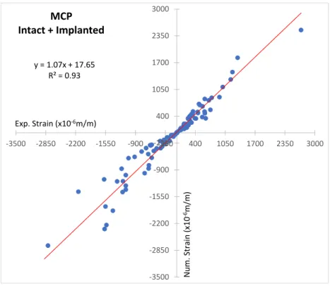
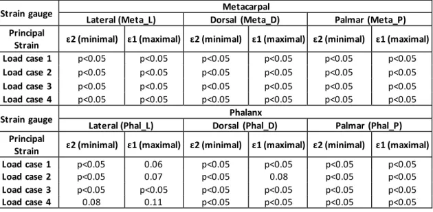
of the principal strain was less than 12%. The four load cases analysed present similar cortical strain behaviour between intact and implanted states, with a reduction at all strain gauges of metacarpal (Meta_L, Meta_D, Meta_P), as well as, on the phalanx at the lateral (Phal_L) and palmar (Phal_P) strain gauges, and a strain increase at the dorsal phalanx (Phal_D) strain gauge. The Pulp Pinch (load case 2 and 4) load presents the highest principal strains. The magnitudes of minimum principal strains (compression) are generally greater than maximum principal strains (tension), with the highest values measured on the dorsal metacarpal (Meta_D) and dorsal phalanx (Phal_D) strain gauges. Significant (p<0.05) minimum and maximum principal cortical strains reduction at the metacarpal bone, as well as, at the lateral (Phal_L) and palmar (Phal_P) phalanx strain gauges between intact and implanted state were observed for all load cases (Table 3). At the phalanx, a significant (p<0.05) minimum and maximum principal cortex strains increase occurred at the dorsal (Phal_D) strain gauge in relation to the intact state. After 25,000 load cycles (1Hz) both metacarpal component and proximal-phalanx component presented good stability without any sign of slippage/release during the pull-out movement. The linear regression correlation value (R2) was 0.93 and the slope was 1.07 between experimental and numerical cortical strains (Figure-
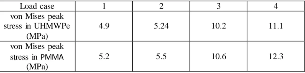
3). The overall absolute difference between experimental and numerical cortical strains (RMSE %) was 11%. Figure 4 shows the patterns of the minimum principal strains in cancellous- bone obtained by using the FE analysis. For all load cases, the implanted phalanx at the dorsal side increased three to fourfold the cancellous-bone strains, while at the palmar side dropped on average three-quarters, as compared to the intact case. At the metacarpal the implanted state reduces to half the cancellous-bone strains close to the condylar implant region and increase slightly at around the implant stem tip region. The highest UHMWPe and PMMA stress was reached in the Pulp Pinch (load case 4) with 11.1 MPa and 12.3 MPa, respectively (Table 4).
Discussion
The aim of the present work is to investigate in-vitro implant–bone load transfer mechanisms with the metal-polyethylene SR MCP System prosthesis. To the authors’ knowledge there are no other studies involving the metal-polyethylene implant in which the stress-strain levels are compared for the intact and implanted MCP joint either in-vitro or using the FE method. The standard deviations of the measured cortical strains were within the range of those found in the literature using other synthetic bones (Completo et al., 2008; Completo et al., 2010). In general, the cortex principal strains in the implanted MCP joint (phalanx and metacarpal) presented a significant reduction (p<0.05) as compared to the intact joint, the exception was the dorsal side of phalanx where a significant cortex strain increase (p<0.05) was observed. These experimental results demonstrate that the MCP joint is not immune to using the metal-polyethylene SR MCP prosthesis. The FE models developed to analyse cancellous-bone, which is the major support structure for the implant, produced correlation, slope, intercept values of the linear regressions and RMSE values in the range of previous experimental- numerical studies performed with synthetic bones (Completo et al., 2011; Completo et al., 2013).In addition, good agreement was revealed between FE and measured strains. As observed experimentally at the cortical bone, cancellous-bone strain behaviour in the implanted MCP joint is very different of the intact state. In the implanted case, the proximal dorsal region of phalanx presents a pronounced cancellous-bone strain increase (three to fourfold), which increases with the joint angle, comparing with the intact condition. Therefore, this strain increase indicates a potential risk of cancellous-bone fatigue failure due to cyclic loads; bone can suffer fatigue failure if the induced strain approaches 60 to 80% of the yield strain (Choi and Goldstein, 1992). These strain levels may occur if the compressive strains in the
cancellous-bone of the intact joints are increased by 50 to 100% due to implantation (Taylor and Tenner, 1997; Burstein and Wright, 1994), which is the present case. The cancellous-bone strain reduction, about 50%, at the implanted metacarpal (head region) and at the palmar side of phalanx indicates a marginal risk of bone resorption due to strain-shielding effect (Gross and Rubin 1995; Frost, 2003). The maximum von Mises stress values reached at the phalanx polyethylene component (UHMWPe) and bone cement (PMMA) were below their fatigue limits (Sauer WL, 1996; Huiskes, 1993), pointing to a reduced risk of the polyethylene component and bone-cement fracture at long-term. All these stress-strain results reveal mainly a potential risk of fatigue failure of support cancellous-bone at phalanx due to cyclic loads, which is enhanced by the magnitude and flexio n angle of joint loads, as well as, by the number of load cycles. Also, the implanted metacarpal strain reduction may point to a long-term risk of cancellous-bone resorption. The identified potential structural risks cannot be directly related to clinical outcomes due to the lack of mid-long- ter m follow-up studies and the absence of published results (Srnec et al, 2017; Aujla et al, 2017). However, one of the primary challenges to metal-polyethylene arthroplasties is the prevention of prosthetic loosening (Murray, 2003; Drake ML, 2010), thus, considering the present strain-stress results, limiting the magnitude of finger forces and finger flexion angle after arthroplasty can contribute positively to the reduction of the overload effect in the cancellous-bone adjacent to the SR MCP phalanx component, reducing the risk of fatigue failure of the support bone.
Common to all experimental-numerical studies, the present study had some shortcomings, one such limitation is concerned with the use of synthetic bones and experimental simplificat io ns required to represent the functioning metal-polyethylene SR MCP implant. The advantage of using artificial bones is that specimen geometry is constant, which optimizes the reproducibility of results obtained in tests. Experimental load-cases were simplified in terms of applied loads and
structural links; however, applied load-cases are representative of major loads acting upon the implant and bone structure. Moreover, due to the comparative nature of the study, it is concluded that the observed strain results are representative of major differences between intact and implanted states.
Conclusions
The main finding of the present study is that the use of the metal-polyethylene implant changes significantly the magnitude of bone strains between intact and implanted states. Therefore, the phalanx cancellous-bone incurs into the long-term risk of fatigue failure due to the localized strain increase for cyclic loads in the range of daily hand activities; this risk is more important than the risk of bone resorption due to strain-shielding effect. Limiting the loads and flexion angle over the joint after arthroplasty may contribute to the improvement of implant longevity and prevention of the risk of implant loosening.
Acknowledgements
This work is supported by the project POCI-01-0145-FEDER-028424-PTDC/EME-SIS/28424/2017, funded by Programa Operacional Competitividade e Internacionalização (COMPETE 2020) on its component FEDER and by funding from FCT – Fundação para a Ciência e Tecnologia on its component OE. TEMA/DEM researchers also acknowledge FCT grant UID/EMS/00481/2013eFCT and the infrastructures support CENTRO-01-0145-FEDER-022083.
Adkinson, J.M., Chung, K.C., 2014. Advances in Small Joint Arthroplasty of the Hand. Plast Reconstr Surg. 134, 1260–1268.
An, K.N., Chao, E.Y., Cooney, .W.P., Linscheid, R.L., 1985. Forces in the normal and abnormal hand. J Orthop Res. 3, 202-211.
ASTM F1839-08, 2012. Standard Specification for Rigid Polyurethane Foam for Use as a Standard Material for Testing Orthopaedic Devices and Instruments, ASTM International, West Conshohocken, PA.
Aujla, R.S., Sheikh, N., Divall, P., Bhowal, B., Dias, J.J., 2017. Unconstrained metacarpophalangeal joint arthroplasties: a systematic review. Bone Joint J. 99, 100-106.
Burstein, A.H., Wright, T.M., 1994. Fundamentals of Orthopaedic Biomechanics, Baltimore Williams&Wilkins, 191–217.
Choi, K., Goldstein, S.A., 1992 A comparison of the fatigue behavior of human trabecular and cortical bone tissue. J Biomech. 25:1371-1381.
Chung, K.C., Ram, A.N., Shauver, M.J., 2009. Outcomes of pyrolytic carbon arthroplasty for the proximal interphalangeal joint. Plast Reconstr Surg. 123, 1521-1532.
Completo, A., Rego, A., Fonseca, F., Ramos, A., Relvas, C., Simões, J.A., 2010. Biomechanica l evaluation of proximal tibia behaviour with the use of femoral stems in revision TKA: an in vitro and finite element analysis. Clin Biomech. 25, 159-65.
Completo A, Pereira J, Fonseca F, Ramos A, Relvas C, Simões J. 2011. Biomechanical analysis of total elbow replacement with unlinked iBP prosthesis: an in vitro and finite element analysis. Clin Biomech. 26, 990-7.
Completo A, Duarte R, Fonseca F, Simões JA, Ramos A, Relvas C. 2013. Biomechanica l evaluation of different reconstructive techniques of proximal tibia in revision total knee arthroplasty: An in-vitro and finite element analysis. Clin Biomech. 28, 291-8.
Completo, A., Simões, J., Fonseca, F., 2008. Experimental Evaluation of Strain Shielding in Distal Femur in Revision TKA. Experimental Mechanics. 48, 817–824.
Cook, S.D., Beckenbaugh, R.D., Redondo, J., Popich, L.S., Klawitter, J.J., Linscheid, R.L., 1998. Long-term follow-up of pyrolytic carbon metacarpophalangeal implants. J Bone Joint Surg. 81, 635–648.
Dickson, D.R., Badge, R., Nuttall, D., Watts, A.C., Talwalkar, S.C., Hayton, M., Trail, I.A., 2015. Pyrocarbon Metacarpophalangeal Joint Arthroplasty in Noninflammatory Arthritis: Minimum 5-Year Follow-Up. J Hand Surg Am. 40, 1956-1962.
Drake, M.L., Segalman, K.A., 2010. Complications of small joint arthroplasty. Hand Clin. 26, 205-212.
Frost, H.M., 2003. Bone's mechanostat: a 2003 update. Anat Rec A Discov Mol Cell Evol Biol. 275, 1081-1101.
Gross, T.S., Rubin, C.T., 1995. Uniformity of resorptive bone loss induced by disuse. J. Orthop. Res. 13, 708-714.
Harris, D., Dias, J.J., 2003. Five-year results of a new total replacement prosthesis for the finger metacarpo-phalangeal joints. J Hand Surg Br. 28, 432-438.
Huiskes, R., 1993. Mechanical failure in total hip arthroplasty with cement. Curr. Orthop. 7, 239-247.
Joyce, T.J., 2004. Currently available metacarpophalangeal prostheses: their designs and prospective considerations. Expert Rev Med Devices. 1, 193-204.
Kung, P.L., Chou, P., Linscheid, R.L., Berglund, L.J., Cooney, W.P. 3rd, An, K.N., 2003. Intrinsic stability of an unconstrained metacarpophalangeal joint implant. Clin. Biomech.18, 119–25. Linscheid, R.L., 2000. Implant arthroplasty of the hand: retrospective and prospective considerations. J Hand Surg Am. 25, 796-816.
Mann, K.A., Bartel, D.L., Wright, T.M., 1991. Ingraffe AR. Mechanical characteristics of the stem-cement interface. J Orthop. Res. 9, 798–808.
Murray, P.M., 2003. New-generation implant arthroplasties of the finger joints. J Am Acad Orthop Surg. 11, 295-301.
Operative technique SR MCP System Metacarpophalangeal Arthroplasty, 2016.
Parker, W.L., Rizzo, M., Moran, S.L., Hormel, K.B., Beckenbaugh, R.D., 2007. Preliminary results of nonconstrained pyrolytic carbon arthroplasty for metacarpophalangeal joint arthritis. J Hand Surg Am 32, 1496–505.
Rizzo, M., 2011. Metacarpophalangeal joint arthritis. J Hand Surg Am. 36, 345-353.
Sauer, W.L., Weaver, K.D., Beals, N.B., 1996. Fatigue performance of ultra-high-molecular-weight polyethylene: effect of gamma radiation sterilization. Biomaterials. 17, 1929-1935. Schmidt, K., Willburger, R.E., Miehlke, R.K., Witt, K., 1999. Ten-year follow-up of silicone arthroplasty of the metacarpophalangeal joints in rheumatoid hands. Scand J Plast Reconstr Hand Surg. 33, 433–38.
Simpson-White, R.W., Chojnowski, A.J., 2014. Pyrocarbon metacarpophalangeal joint replacement in primary osteoarthritis. J Hand Surg Eur Vol. 39, 575-581.
Srnec, J.J., Wagner, E.R., Rizzo, M., 2017. Implant Arthroplasty for Proximal Interphalangea l, Metacarpophalangeal, and Trapeziometacarpal Joint Degeneration. J Hand Surg Am. 42, 817-825. Taylor, M., Tanner, K.E., 1997. Fatigue failure of cancellous bone: a possible cause of impla nt migration and loosening. J. Bone Joint Surg. Br. 79, 181–182.
Trail, I.A., Martin, J.A., Nuttall, D., Stanley, J.K., 2004. Seventeen-year survivorship analysis of Silastic metacarpophalangeal joint replacement. J Bone Joint Surg Br. 86, 1002-1006.
Wall, L.B., Stern, P.J., 2013. Clinical and radiographic outcomes of metacarpophalangeal joint pyrolytic carbon arthroplasty for osteoarthritis. J Hand Surg Am. 38, 537-543.
Weightman, B., Amis, A.A.., 1982. Finger joint force predictions related to design of joint replacements. J Biomed Eng. 4: 197-205.
LIST OF FIGURES LEGENDS
Figure 1 – a) Strain gauges locations at Lateral side (Meta_L, Phal_L); b) Strain gauges locations at Dorsal side (Meta_D, Phal_D); c) Strain gauges locations at Palmar side (Meta_P, Phal_P); d) SR MCP prosthesis components; e) Loading machine and experimental setup; f) Load case at 15º of flexion (Tip pinch); g) Load case at 34º of flexion (Pulp pinch).
Figure 2 – Mean and standard deviation of the measured principal strains (ε1 - maximal and ε2 - minimal) at each strain gauge (Meta_L, Phal_L, Meta_D, Phal_D, Meta_P, Phal_P) location on the intact and implanted state for the Tip and Pulp Pinch activities.
Figure 3 - Linear regression between experimental and numerical strains.
Figure 4 - Minimal principal strains in cancellous-bone of the intact and implanted MCP joint for the Tip (load case 3) and Pulp (Load case 4) pinch loads.
FIGURES: Figure 1 Tip pinch posture Load cell Fixture Proximal phalanx Load linear actuator Pulp pinch posture Metacarpal 34o 15o Meta_D Phal_D M eta_L Phal_L Meta_P Phal_P 12mm 9mm 12mm 9mm 12mm 9mm
Lateral Dorsal Palmar SR™
MCP M et ac ar pa l co m po ne nt (M ) P ha la nx co m po ne nt (M )
Figure 3 y = 1.07x + 17.65 R² = 0.93 -3500 -2850 -2200 -1550 -900 -250 400 1050 1700 2350 3000 -3500 -2850 -2200 -1550 -900 -250 400 1050 1700 2350 3000 MCP Intact + Implanted N um . Strain (x 1 0 -6m /m ) Exp. Strain (x10-6m/m)
Table 1 – Load cases analysed
Load case Isometric hand activity Joint angle Joint force
1 Tip Pinch 15° 122 N
2 Pulp Pinch 34° 134 N
3 Tip Pinch 15° 245 N
4 Pulp Pinch 34° 280 N
Table 2 - Material properties used in the FE models.
Components Material Elastic modulus
(GPa)
Poisson’s ratio
Cortical bone Composite
material
16.7 0.3
Cancellous bone Polyurethane foam
0.155 0.3
Metacarpal component Cobalt Chrome 210 0.3
Phalanx component UHMWPe 0.5 0.3
Bone cement PMMA 2.28 0.3
Table 3 - P-values from T-tests, performed to test the difference of mean of cortex strains between implanted and intact MCP joint.
Strain gauge Metacarpal
Lateral (Meta_L) Dorsal (Meta_D) Palmar (Meta_P)
Principal
Strain ɛ2 (minimal) ɛ1 (maximal) ɛ2 (minimal) ɛ1 (maximal) ɛ2 (minimal) ɛ1 (maximal)
Load case 1 p<0.05 p<0.05 p<0.05 p<0.05 p<0.05 p<0.05
Load case 2 p<0.05 p<0.05 p<0.05 p<0.05 p<0.05 p<0.05
Load case 3 p<0.05 p<0.05 p<0.05 p<0.05 p<0.05 p<0.05
Load case 4 p<0.05 p<0.05 p<0.05 p<0.05 p<0.05 p<0.05
Strain gauge Phalanx
Lateral (Phal_L) Dorsal (Phal_D) Palmar (Phal_P)
Principal
Strain ɛ2 (minimal) ɛ1 (maximal) ɛ2 (minimal) ɛ1 (maximal) ɛ2 (minimal) ɛ1 (maximal)
Load case 1 p<0.05 0.06 p<0.05 p<0.05 p<0.05 p<0.05
Load case 2 p<0.05 0.07 p<0.05 0.08 p<0.05 p<0.05
Load case 3 p<0.05 p<0.05 p<0.05 p<0.05 p<0.05 p<0.05
Table 4 - Peak values of von Mises stresses in UHMWPe and PMMA materials.
Load case 1 2 3 4
von Mises peak stress in UHMWPe
(MPa)
4.9 5.24 10.2 11.1
von Mises peak stress in PMMA
(MPa)