Contents lists available atScienceDirect
Progress in Materials Science
journal homepage:www.elsevier.com/locate/pmatsciRevisiting fundamental welding concepts to improve additive
manufacturing: From theory to practice
J.P. Oliveira
⁎, T.G. Santos, R.M. Miranda
UNIDEMI, Department of Mechanical and Industrial Engineering, NOVA School of Science and Technology, NOVA University of Lisbon, 2829-516 Caparica, Portugal
A R T I C L E I N F O Keywords:
Additive manufacturing Arc welding
Electron beam additive manufacturing Laser additive manufacturing Energy density
Microstructure
A B S T R A C T
Additive manufacturing technologies based on melting and solidification have considerable si-milarities with fusion-based welding technologies, either by electric arc or high-power beams. However, several concepts are being introduced in additive manufacturing which have been extensively used in multipass arc welding with filler material. Therefore, clarification of funda-mental definitions is important to establish a common background between welding and additive manufacturing research communities. This paper aims to review these concepts, highlighting the distinctive characteristics of fusion welding that can be embraced by additive manufacturing, namely the nature of rapid thermal cycles associated to small size and localized heat sources, the non-equilibrium nature of rapid solidification and its effects on: internal defects formation, phase transformations, residual stresses and distortions. Concerning process optimization, distinct cri-teria are proposed based on geometric, energetic and thermal considerations, allowing to de-termine an upper bound limit for the optimum hatch distance during additive manufacturing. Finally, a unified equation to compute the energy density is proposed. This equation enables to compare works performed with distinct equipment and experimental conditions, covering the major process parameters: power, travel speed, heat source dimension, hatch distance, deposited layer thickness and material grain size.
1. Introduction
Additive manufacturing allows structures fabrication in a layer-by-layer deposition process and is revolutionizing the manu-facturing industry due to its ability to obtain near-net shape products, in a short time span, with almost no material waste.
An upmost key feature of additive manufacturing based on melting and solidification, is the use of fundamental knowledge generated by decades of research on welding metallurgy and technologies, based on electric arc and high-energy density beams (laser and electron beam). This experience in welding can be used to better understand the additive manufacturing process and the im-plications on the microstructural features of the produced parts, including the origin of internal defects (type, morphology, location and quantity).
Most prevailing industrial applications of additive manufacturing use laser beam systems which, under appropriate process control, produce parts with good dimensional precision and surface finish[1–3]. However, electron beam-based systems tend to deliver sound parts with better mechanical properties, since the process is developed in a vacuum chamber at a uniform high temperature, which decreases residual stresses that build-up during layer deposition. Both electron and laser systems require high
https://doi.org/10.1016/j.pmatsci.2019.100590
Received 24 July 2018; Received in revised form 7 June 2019; Accepted 23 July 2019 ⁎Corresponding author.
E-mail address:[email protected](J.P. Oliveira).
Available online 01 August 2019
0079-6425/ © 2019 Elsevier Ltd. All rights reserved.
investment costs. Thus, additive manufacturing with electric arc and plasma are dedicated to large parts manufacturing.
Alternatively to high-power beams, electric arc heat sources can be used in additive manufacturing where the production rate is a major requirement[4]. Nevertheless, laser or electron beam sources are preferred for parts with fine features or requiring high dimensional tolerances, due to their small size heat source.
Additive manufacturing techniques based on melting and solidification induce complex thermal profiles throughout the material [5,6]. Whether, the added material is powder or wire, the first layer is melted and solidified onto a substrate. When a second layer is deposited on the previous, the introduced heat must completely melt this second layer and partially re-melt the one underneath. Moreover, a heat affected zone is created in the first deposited layer, which, depending on the material, may promote additional solid-state transformations. This process is repeated over and over until the part is complete. Therefore, the heat introduced to deposit each layer generates successive heat affected zones on previously deposited layers, in a process similar to multipass fusion welding [7–10]. As in welding, additive manufactured parts experience non-equilibrium solidification[11–13], due to fast cooling rates observed. The effect of multiple thermal cycles over these non-equilibrium structures may promote the formation of new phases and precipitates if the permanence time at a specific temperature for the solid-state transformation to occur is reached.
As additive manufacturing technologies based on electric arc or high-power beams are still being matured, well-established knowledge from welding metallurgy can be transferred to better understand and improve additive manufacturing techniques.
Currently, the processing parameters used by the additive manufacturing community lack comparability and, thus, a compre-hensive effort to encompass the vast generated knowledge over the past years is necessary to foster the development of additive manufacturing techniques into new applications.
Recently, a very comprehensive revision on additive manufacturing was published by DebRoy et al.[1]. The present paper aims to revise fusion welding concepts applicable to additive manufacturing of metals, highlighting the similarities between both technol-ogies and the procedures used in welding that can be directly applicable in additive manufacturing. Specifically, this paper focus on strategies to control the microstructure of the fusion zone in welds in terms of heat source manipulation, optimization of operating procedures and correction of microstructure, to improve mechanical performance and avoid internal defects in additively manu-factured parts. In fact, most of existing literature on additive manufacturing is built on welding technology and welding metallurgy. Therefore, this paper intends to evidence how the welding and additive manufacturing communities can establish a synergetic relationship. Concerning additive manufacturing process optimization, distinct criteria (geometric, energetic and thermal) are pro-posed to determine an upper bound limit for the hatch distance. Finally, an equation to compare energy densities used with different additive manufacturing equipment and varying the most relevant process parameters (power, travel speed, hatch distance, layer thickness, grain size and diameter of the heat source) is proposed.
Nomenclature
BD Building Direction CAD Computer Aided Design CMT Cold Metal Transfer DR Deposition Rate
E Energy
EBSD Electron Backscattered Diffraction HI Heat Input
HIP Hot Isostatic Pressing LHI Linear Heat Input MAG Metal Active Gas MIG Metal Inert Gas PDD Powder Deposition Rate TIG Tungsten Inert Gas
WAAM Wire and Arc Additive Manufacturing WPS Welding Procedure Specification Cp heat capacity
dLaser laser beam diameter dHeatSourcediameter of the heat source dt track width
E energy
Ed energy density
Eeff effective energy per unit of area F volumetric fluency
h hatch spacing/distance Heatfusion latent heat of fusion
I current intensity m mass of material K thermal conductivity
K0 modified Bessel function of the second kind and zero order
L travelled length
T temperature
T0 initial temperature of the base material tint laser/material interaction time
o overlap distance between two consecutive points in the same hatch
P welding power
R radial distance Rm melted radius Rpowder powder feed rate
v welding speed
V voltage
x distance travelled by the heat source
w layer width
α thermal diffusivity
β dimensionless parameter defined by the grain size to heat source diameter ratio
ρ density of the material
ρbed relative density of the powder-bed η heat source efficiency
φ wire diameter
2. Welding
The need to produce complex parts constituted a major driving force for the development of welding technologies. In fact, welding dates back from 8000 bC, namely brazing, where a molten metallic alloy with a low melting temperature was poured between two solid materials promoting joining[14]. However, it was just in beginning of the 20th century, that welding became a reality in industry, after major scientific and technological breakthroughs. Some of these developments included mastering of the electrical arc, discovered in the 1800′s and easier access to electricity after World War I. However, it was after World War II that major developments were achieved, both in the technology itself and in materials behavior. Because of such technological conquests, welding disseminated rapidly and was finally embraced by the industry for mass production of complex structures.
One of the most important developments was the invention of Tungsten Inert Gas (TIG) process in 1942[15], where a non-consumable tungsten rod was used to initiate the electric arc under the protection of an inert gas. TIG is commonly used to join a wide variety of materials including steels[16], Ni-based[17], Ti-based[18]and Aluminum alloys[19], for example. The fact it does not use a filler material limits its use to thin plates or tubes.
Further developments encompassed the use of a continuous wire feed, which significantly increased production rates in an automatized process. Metal Inert/Active Gas (MIG/MAG) was developed late in the 40́s of the 20th century. In this process, an electric arc is established between a consumable electrode and the base material, under a shielding gas atmosphere. The gas can be inert (He or Ar) or active (mostly CO2or other gas mixtures)[20,21]. Melting of both electrode and base materials to join is promoted by the heat generated in the electrical arc. This process is one of the most used in industry, in either manual or in robotized welding cells.
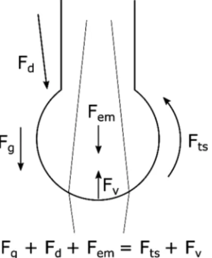
Melting of the consumable rod originates the formation of drops that are directed to the molten pool through a combination of forces due to: electromagnetic effects (Fem), gravity (Fg), surface tension (Fts) and vaporization (Fv).Fig. 1depicts the contribution of each acting force either to push or to pull a drop out of the consumable rod. The gas type, rod diameter, feeding rate and stick-out affect the acting forces and, thus, the drop detachment form. Depending on the current voltage and intensity, three main regimes for drop detachment from the tip of the wire can occur and these are: short circuit, spray and globular. Nevertheless, far more modes have been identified by researchers and recognized by the International Institute of Welding.
Short circuit occurs at both low voltage and current intensity leading to small drop size, being easy to control the deposited metal [22]. However, the deposition rate is low and in cases where productivity is a major requirement, globular transfer is desirable despite the large quantity of fumes and particles emitted.
The need for increased productivity and better weld quality pushed for the development of several variants of MIG/MAG. Synergic MIG is an alternative technique developed in the early 1980′s which is now widely used in industry. This welding source allows to vary the wire feed rate, together with the power, while the voltage slightly varies with the current intensity. It measures the arc voltage and compares this value to a reference one so that, when necessary, the feed rate is corrected to have a continuous and regular molten pool. The source is electronically controlled.
More recently, another variant of MIG/MAG welding was developed that permits to control the molten pool at high welding speeds. Cold Metal Transfer (CMT) uses a push and pull electro-mechanical system acting on the consumable rod allowing to have regular small drop size at low heat input. Some authors find it interesting for additive manufacturing using electric arc, though the deposition rate is low[23].
The use of high-power beams applied in welding dates from the 1960′s and is now recurrent in industry[24]. Both laser and electron beam share common features which include: small beam size, precise control of beam shape and position, and very high energy density. The extension of the thermal affected areas is narrow with consequent low residual stresses and almost no distortions
Fig. 1. Forces acting on a drop hanging from a wire during welding: Fg– gravity; Fd– plasma jet; Fem– electromagnetic forces/Pitch effect; Fts– surface tension; Fv– vaporization.
[25,26]. Additionally, both processes can be used for dissimilar welding[27–34].
In electron beam welding, a beam of electrons is produced in the cathode and accelerated onto the materials to be joined, which act as the anode. In the interaction area, the kinetic energy of the electrons is converted into heat, melting the base materials and promoting joining. This is a very efficient energy process, since up to 95% of the kinetic energy is converted into heat[34].
In laser welding, a monochromatic beam of light radiation, coherent and with virtually no divergence, is used to heat the material. Depending on the laser beam wavelength and the absorptivity of the materials to be joined, the efficiency of the process varies. For metallic alloys the absorptivity increases when decreasing the laser beam wavelength, which partially explains the weldability improvements observed when transitioning from CO2lasers (with a beam radiation wavelength of 10.6 μm) to Nd:YAG and fiber ones (with 1.06 μm of wavelength)[35,36]. Both electron and laser beam welding are commonly referred as high-density energy welding processes, owing to the ability to decrease the beam spot significantly.
Electron beam welding was first developed but required a vacuum chamber[37,38]. However, it does not need consumables, such as gases, to protect the molten pool and adjacent zones from oxidation, during the process. Currently, pumping systems enable high production rates, with significant benefits to industry.
Laser welding appeared after electron beam welding and became rapidly popular since no vacuum chamber was needed (the process could run in open air atmosphere) with less equipment investment. Currently, a wide range of laser welding systems exist and the most used are Nd:YAG, fiber and CO2.
Similarly to electron beam welding, the high versatility of laser welding makes it a unique technique capable of performing both similar and dissimilar materials joining[39–42]. During laser welding, shielding gases are necessary to protect the fusion and heat affected zones from oxidation and/or incorporation of undesired gases and particles[43,44].
The high energy density of both processes originates a keyhole welding mode when the heat is transferred in depth and the weld width is narrow[45]. When keyhole mode is observed the welds tend to have an aspect ratio, defined by the depth to width ratio, larger than 1. If the energy density is reduced, conduction welding mode is observed and the depth to width ratio in the fusion zone is well below 1. Though in deep welding keyhole mode is desirable, for thin sheets and dissimilar materials welding, conduction mode is preferred. A mixed mode of keyhole and conduction welding can also be observed at intermediate values of energy density[46,47]. Besides the technological aspects of welding processes, extensive and detailed studies were performed on welding metallurgy. The processes and their effects on materials were also subjected to tremendous research efforts to understand the connection and in-teraction between processing, microstructure and mechanical properties. For accurate metallurgical understanding and description of the underlying phenomena, new tools for materials analysis, such as dilatometry[48,49], scanning electron microscopy[39,50–53], transmission electron microscopy[54–56], X-ray diffraction[57–59]and software for thermodynamics, thermal and mechanical behavior[60], have been developed and are now extensively used by both academia and industry.
Associated to any fusion-based welding process there are four major aspects to consider and these are of thermal, chemical, metallurgical and mechanical domains. The thermal effect due to high temperature cycle is, eventually, the most important since it affects the thermal distribution and the metallurgical behavior of the materials to be joined, as well as, its mechanical performance, so these are discussed separately.
2.1. Thermal aspects
The quantity of heat introduced during welding, the thermal conductivity and specific heat of the base material(s) are funda-mental to determine the cooling rate, and this is of paramount importance to control solid-state transformations upon cooling that may occur in the heat affected and fusion zones.
Rosenthal, in 1941, developed the theory for the thermal cycle description and presented two equations that are still the basis of analytical and numerical mathematical modelling of heat transfer in welding[61]. Despite its extensive use, it is worth to mention that these equations have some limiting assumptions, such as: it considers punctual heat sources, heat dissipation simply by con-duction under equilibrium conditions, disregarding convection losses in the dynamic molten pool and surface radiation. Additionally, it does not consider phase transformation enthalpy, including melting, and the variability of thermal properties with temperature. The developed solutions for bi and three-dimensional heat flow, observed in thin and thick plates, respectively, are described by Eqs. (1) and (2), allow the calculation of the peak temperature T in [K] at any point distant, x, from the heat source:
= T T P 2 Ke K v R 2 0 v x/2 0 (1) = T T P 2 K Re 0 v(R x)/2 (2) Where:
– T [K], is the temperature at a given position; – T0[K], is the initial temperature of the base material; – P [W], is the welding power;
– K [W m−1K−1], is the thermal conductivity of the material; – K0is a modified Bessel function of the second kind and zero order; – α [m2s−1], is the thermal diffusivity of the material;
– R [m], is the radial distance from the weld centerline, that is, R = (x2+ y2)1/2or R = (x2+ y2+ z2)1/2for 2D and 3D heat flow, respectively;
– v [m s−1], is the welding speed;
– x [m], is the distance from the heat source.
The heat input, HI in [W s mm−1] or [J mm−1], is a fundamental parameter in welding, controlling the quantity of heat introduced into the material, and is defined as the welding power (Q) [W] to welding speed (v) [m s−1] ratio, according to Eq.(3):
=
HI Q
v (3)
With η [%] being the efficiency of power transferred, that is, the ratio between the power delivered and the one effectively introduced into the material.
The physical meaning of the heat input is, thus, the energy [J] introduced by unit of length [m]. So, Eq.(3)is equivalent to Eq. (4), considering that the power is the energy per unit of time, E/t, while the travel speed is the distance covered per unit of time. So, Eq.(4)establishes the final definition of heat input in one dimension, that is:
= = = HI Q v E L E t L t (4)
where E is the energy [J] and L [m] the distance travelled by the heat source. For arc welding, the heat input is defined by:
= = = HI V I v V I t L E L (5)
where I [A] and V [V] are the electric current intensity and voltage, respectively, and v [m s−1] is the travel speed of the heat source. The energy efficiency, η, depends on the welding process and can vary from about 95% for electron beam[34]and up to 80% for laser [62], while it is lower for gas metal arc welding (30–50%)[63]. This parameter considers the energy losses for gas ionization, to surrounding environment and to the filler material, if any.
The heat input is fundamental in welding, since it affects the volume and shape of the molten material, the extension of both heat affected and fusion zones and the cooling rate in these regions. In high-power density processes, such as electron beam and laser welding, another important parameter is the energy density, which controls the welding mode (keyhole, conduction or mixed mode). The energy density is the energy deposited per unit of interaction area and has units of [J mm−2] and is also referred to as the power density [W mm−2].
The concept of power density is not considered in arc welding since the arc/material interaction area is difficult to quantify as it varies during welding, even when automated.
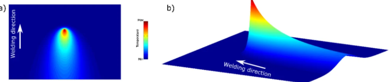
Since the heat is deposited locally on the material surface through a moving heat source, a three-dimensional distribution of temperature, which identifies the peak temperature at any point of a weld and allows to determine the cooling rate, can be computed. Both the maximum temperature and the cooling rate control the microstructural modifications and the residual stresses (magnitude and pattern), along the welded joint.Fig. 2depicts the peak temperature evolution along a butt weld, in the so-called thermal solid, as well as, the isothermal lines created by the heat source.
2.2. Chemical and microstructural aspects
In the melted region, due to high temperatures, different chemical reactions can occur: (1) within the liquid; (2) between the liquid and the solid filler material, if any; (3) between the liquid and the surrounding atmosphere. The main consequences of each type of reaction are: (1) volatilization of low vapor pressure elements with corresponding modification of the chemical composition of the molten metal; (2) pores and lack of fusion; (3) oxide inclusions. Loss of elements generally leads to poor mechanical properties, as well as, to the formation of defects.
Solidification occurs by epitaxial grain growth, that is, it starts on non-melted solid grains from the heat affected zone, which is
favored by grains with a crystallographic orientation parallel to the heat flow direction. This is a feature of welding solidification that is also observed in casting, though at smaller scale. The microstructures in the fusion zone can have different morphologies, such as, planar, cellular and dendritic and these are controlled by: temperature gradient (T), grain growth rate (R), undercooling (ΔT) and chemical composition. While the morphology is controlled by the grain growth rate to temperature gradient ratio (G/T), the crystal growth is governed by the G.R product as shown inFig. 3. With increasing constitutional undercooling, the microstructure may shift from planar to cellular and from this to dendritic or exhibit a combination of these. The first grains solidify as dendrites since the underneath base material is much cooler than the molten metal and, so, the thermal gradient is predominant relative to crystal growth. However, after some time the supercooling effect decreases, and solidification tends to be planar, in an epitaxial grain growth mode, where the new grains form over the previous ones, and growth along more compact crystallographic directions perpendicular to isothermal lines, in a competitive grain growth process.
2.3. Mechanical aspects
Since there is always a thermal gradient along a weld, expansion and contraction upon heating and cooling, respectively, are not uniform and thus, the material undergoes differential deformation. This creates permanent plastic deformations, distortions and residual stresses[64–66]. The pattern of these stresses depend on the joint configuration, material thermo-physical properties (thermal conductivity and coefficient of thermal expansion) and mechanical properties (elastic modulus, yield strength and Poisson ratio).Fig. 4depicts a common residual stress pattern observed in a butt welded joint of a thin plate.
Since there is a sharp temperature gradient near the weld, the material experiences distinct rates of expansion and contraction in adjacent sections. As the temperature increases, expansion of an area is constrained by the adjacent one, further away from the heat source, which is cooler. As a result, tensile and compressive stresses are generated in the fusion and heat affected zones, as sche-matically shown inFig. 4. If the flow stress is surpassed, causing the material to yield locally, the residual stresses decrease. As the temperature lowers, adjacent hotter material reverses this plastic strain and tensile stresses form. Depending on the rigidity of the structure residual stresses may equal or exceed the yield stress of the material. If these residual stresses and residual strains imposed at high temperatures overcome the yield strength of the material distortions occur, as schematically shown inFig. 5.
Another important contribution to the formation and magnitude of residual stresses are the solid-state transformations. As an example, in high strength steels, the martensitic transformation can be followed by nearly 4% dilation, or about 1.4% linear strain. Other factors such as grain size, affects the magnitude of volume changes and therefore may impact the developed residual stresses. Pre- and/or post-heating are typically used to reduce residual stresses, since the thermal cycle is smoother and the cooling rate decreases. However, other strategies can be used, such as deposition sequence and weld length, besides the control of the heat input, and the use of post-weld heat treatments.
2.4. Multipass welding
In multipass or multi-run welds, microstructural refinement is observed with improvements of weld toughness and reduction of residual stresses[67]. The main reasons are:
– each subsequent thermal cycle refines or “normalizes” the grains of the previous weld metal; – the previous pass has an effect of pre-heating the material and, so, the cooling rate decreases; – subsequent thermal cycles tend to anneal out residual stresses caused by previous passes.
Thus, successive thermal cycles affect the microstructure of both as-solidified material and heat affected zones. The subsequent pass partially remelts the previous one and, if there are no solid-state phase transformations, grains grow by epitaxy. Nevertheless, the dislocation density of the previously solidified weld metal can hinder excessive grain growth and cause recrystallization to occur. A schematic representation of a multipass weld is depicted inFig. 6. It is observed that different regions of the weld metal may be reheated multiple times during deposition of subsequent beads. For example, region A is only reheated once due to deposition of weld bead number 2. In opposition, region B is reheated twice due to weld beads number 2 and 3. Therefore, it is expected that the resulting microstructure is different in regions A and B. This behavior can be even more complex depending on the deposition sequence and the heat input of each weld bead, which influence the cooling rate of subsequent passes. Therefore, a graded micro-structure is often observed along deposited beads, with characteristics and morphologies that depend on the material solid-state transformations.
In multipass welding, there is no guidance or consensus on how to analyze the heat input. However, a common procedure adopted in design and in welding procedure specifications (WPS) is to record the heat input for each single pass and calculate an average value that is later used in process qualification.
During multipass welding, only a small part of the reheated heat affected zone is subjected to high temperature peaks during a subsequent pass (Fig. 7). Thus, the heat affected zone of previous passes experiences a mild post-weld heat treatment.
As previously stated, welding microstructures largely depend on the material behavior under a thermal cycle and so, precipitation or formation of new phases can be observed depending on the peak temperature and the cooling time that each region experienced during welding. However, it must be noticed that some materials, such as steels or aluminum alloys, undergo reheat cracking.
3. Additive manufacturing
Several technologies of fusion-based additive manufacturing are currently under development. They all have two common fea-tures: (1) the use of computer aided design (CAD) tools to create parts and (2) the part is manufactured in a layer-by-layer deposition strategy. The most important advantage of this new way of manufacturing relies in the freedom to produce, virtually, any shape and geometry, in any material or combination of distinct materials. Other advantages emerge, such as: material savings, independence of
Fig. 4. Schematic of a butt welded joint showing a residual stress pattern.
Fig. 5. Example of angular distortion due to a weld deposited bead.
Fig. 6. Schematic representation of a multipass weld. Numbers 1 to 6 represent the sequence of passes. Dotted lines correspond to the heat affected zones created by each pass. Zone A is reheated once (by weld pass 2), whereas zone B is reheated twice (by weld passes 2 and 3) (adapted from [68]).
human interaction and short production times in line with new manufacturing and costumer delivering approaches[69].
Though solid-state manufacturing technologies are being investigated, fusion-based ones are still the most interesting due to productivity issues. As far as heat sources are concerned, laser beam, electron beam, electric arc and plasma are the ones under use, while materials to melt can be in the form of powder or wire.
The thermal effects of successive melted layers deposited on top, or aside, of each other are of paramount importance to prevent defect formation, microstructural features and mechanical performance of the produced parts[70]and, thus, the next section is devoted to analyze the specific effects of multiple thermal cycles.
3.1. Thermal aspects
While in welding, the heat input concept is well established and it has a linear dimension, in additive manufacturing this largely varies between research groups, especially those using laser-based systems. Firstly, an in-volume energy density concept, ED [J mm−3], was introduced. This energy density, captured from welding, was adjusted by introducing new parameters, namely, the hatch distance, h [mm], which is the lateral distance between two consecutive passes, and the layer thickness[71–74](or track width [75]), d [mm], as described by Eq.(6), with P [W] and v [m s−1] being, respectively, the power and the travel speed of the heat source.
=
ED P
v h d (6)
Haberland et al.[75]further extended the concept of energy density depicted in Eq.(6)(using the track width term instead of layer thickness) by introducing Eqs.(7) and (8), depending if the track width (dt) exceeded the hatch (h) distance or not, and inserting new variables, such as the laser beam diameter, dLaser[mm], and the relative density of the powder-bed, ρbed, with arbitrary units. Despite the units presented in Haberland’s work[75]are inappropriate, dimensional analysis using correct units ensure that both Eqs.(7) and (8)exhibit units of [J mm−3], that is, in-volume energy density.
= ED P d h d, for h d bed Laser t (7) = <h< ED P d h d 2 h d , for 0 d bed Laser t t (8)
Another term that is widely used in additive manufacturing is the linear heat input (LHI) [J mm−1][76–80]which is defined by Eq.(9)as:
=
LHI P
v (9)
Other authors[81]have also defined an effective energy per unit of area (Eeff) [J mm−2] as in Eq.(10), and for powder fed systems, a powder deposition density (PDD) [g mm−2] as in Eq.(11), where R
powderis the powder feed rate in [g min−1].
= E P v d eff Laser (10) = PDD R v d powder Laser (11)
Finally, a volumetric fluence, F [J mm−3], was also defined in[82]for laser additive manufacturing based on pulsed wave heat sources, by introducing the laser beam/material interaction time, tint[s], instead of the travel speed. This last one is replaced by an overlap distance between two consecutive laser pulses within the same track, o [mm], so that:
=
F t P
h d o
int
(12) Currently, there is no consensual definition on how to quantify the heat introduced in each deposited layer, which is fundamental to control solidification and molten metal transfer, in case of wire feed systems. In fact, all these equations are empirical without phenomenological physical demonstration.Table 1resumes the most used physical quantities considered in additive manufacturing. The deposition rate, DR [kg h−1], is a parameter of critical importance, when productivity is a major concern, and this is calculated using the layer thickness (d) and width (w), and the density of the powder material (ρ), following Eq.(13)for powder-bed systems. In case of wire feed systems, Eq.(14)can be used to determine the deposition rate, considering the wire diameter, ɸ.
=
DR d·w·60· (13)
=
DR 2·60· (14)
Mathematical modelling of additive manufacturing is not a simple task, particularly if other than thermal analysis is envisaged, as material transfer and structural analysis[83]. Several research efforts are ongoing, attempting to predict component characteristics that could accomplish process certification[1]. This is a very important area that will allow researchers to have a deeper under-standing on the peculiarities of the process, in order to improve it and complete parts with optimized microstructures and enhanced mechanical and functional properties.
3.2. Thermal analysis of additive manufacturing in light of welding technology
The well-established concept of heat input used in fusion welding can be generalized to additive manufacturing, if a proper interpretation of linear, or 1D heat input, is used. That is, the physical quantity of heat input based on “energy per length” must be used instead of “power per velocity”.
Therefore, a simple thermodynamic analysis, based on the identification of: (i) a control volume and (ii) an energy balance, leads to conclude that, the 3D equivalent of heat input for additive manufacturing is “Energy per Volume” and is given inTable 2.
The demonstration of the previous equation regarding the equivalent 3D heat input (or in-volume heat input), HI3D, for additive manufacturing consists of:
– Defining a 3D control volume, Δx × Δy × Δz, encompassing all the melted material (Fig. 8);
– Quantifying the summation of the energy input, due to multiple passes, spaced by a lateral displacement (hatch distance, h). It is important to notice that both end passes (1 and 4 inFig. 8) contribute with just one half each to the energy balance;
– Dividing this energy input summation by the volume of melted material encompassed in the control volume (Eq.(15)).
= = ×
× ×
HI Energy
Volume
Number of passes Energy per pass
x y z ,
3D
(15) Since the number of passes that fully contributes to the energy input is Δx divided by h, and noticing that the energy per pass is the power (Q) multiplied by time (t), the previous equation can be rewritten according to Eq.(16)as:
= HI ·Q·t x· y· z, 3D x h (16) The time (t) that each pass is under the control volume corresponds to the length (Δy) divided by the linear travel speed (v), and, therefore Eq.(16)can be rearranged into Eq.(17):
= HI x· y· z, 3D x·Q· y h·v (17) Table 1
Summary of the main equations for energy/power calculations in additive manufacturing found in the literature.
Designation Equation Source
Linear heat input [J mm−1]
=
LHI Pv [76–80]
Effective energy per unit of area [J mm−2]
=
Eeff v dLaserP [81]
Energy density or volumetric fluency [J mm−3]
= F tint Ph d o [82] Energy density [J mm−3] = ED v h dP [71–74] Energy density [J mm−3] = ED P bed dLaser h d [75] Energy density [J mm−3] =
(
)
ED P 2 bed dLaser h d h dt [75]Powder deposition density [g mm−2]
=
PDD R
This equation can be simplified resulting in Eq.(18), which provides the 3D generalization of heat input in additive manu-facturing, referred as energy density (ED):
= =
HI Q
v·h· z ED,
3D (18)
3.3. Microstructural effects in fusion-based additive manufacturing
The energy density highly affects the amount of heat deposited in a certain point, and so the heat transfer conditions. This is critical since the energy density governs the deposition rate and the productivity, but it cannot be seen separately from the material solid-state transformations and its effect on the mechanical performance. Basically, metallic alloys have one or more of the three basic types of solid-state transformations: (1) those leading to precipitation, as most aluminum alloys, which can either produce strain hardening or material softening; (2) the inexistence of solid-state transformations, as in ferritic and austenitic stainless steels; (3) the formation of predicted phases after the equilibrium phase diagrams or metastable ones in rapid cooling conditions.
Table 2
Heat input calculation for welding (1D) and for additive manufacturing (3D).
Heat Input for welding (1D) Heat Input for Additive Manufacturing (3D)
= =
HI1D Qv EnergyLength HI3D=VolumeEnergy =v·h· zQ
Where: Q [W] is the heat source power, v [m s−1] is the travel speed, h [mm] is the hatch distance and Δz [mm] is the thickness of the melted layer. This equation is applicable in wire and arc additive manufacturing (WAAM), since this process is very similar to multiple welds overlapped (fully or in part) and in laser or electron beam-based additive manufacturing where fusion occurs.
Fig. 8. Control volume used to determine the in-volume heat input (or energy density) during additive manufacturing.
An interesting feature of fusion-based additive manufacturing is its potential to obtain very small grain size due to the high cooling rates observed. For most metallic engineering alloys, this increases strength[84–86], though other materials behave dif-ferently[87–89]. However, the thermal cycle experienced by the as-built part may favor grain growth if there is sufficient residence time at critical temperatures for grain coarsening. Therefore, the building sequence can be optimized to minimize such potential undesirable effects.
With additive manufacturing technologies it is possible to develop chemically graded structures as exemplified in[90–92], and schematically shown inFig. 9. In dissimilar welding, there are materials pairs with a vast potential of applications, if successful joined. Examples include: austenitic to ferritic steels joining[93], Ni-based alloys to steels[50,94], and Ni- to Ti-based alloys[29,95]. In all cases, successful joining is defined by a sound weld joint with mechanical properties adequate for the envisaged application. This is not an easy task due to limited control of chemistry in the fusion zone which can lead to the formation of detrimental intermetallic phases and therefore to a significant decrease in the mechanical properties. In fact, a smooth transition between one base material into the other would be a more desirable scenario during dissimilar welding. In additive manufacturing, this can be accomplished through a precise control of process parameters [90,96]. Furthermore, by controlling the chemical composition throughout the part, it is possible to avoid chemical composition ranges where undesirable phases are formed thus circumventing them.
Another interesting feature, in parts manufactured by additive manufacturing, is the capability to control texture along the part. For example, recent works have shown that by changing the scan strategy it is possible to modify the grain characteristics along the part[5,97–99]. Texture control in fusion welding is significantly more difficult. Because of this capability, new and more functional applications can be obtained in parts fabricated by additive manufacturing, provided that the control of the microstructure yields interesting structural and/or functional properties.
From the examples highlighted above, it is clear that the microstructural control that can be achieved in additive manufacturing is an important characteristic, since it can overcome some of the most intricate problems observed in conventional manufacturing processes. To this sense, the potential to create functionally graded structures, either by controlling the composition and/or the grain structure, is a clear advantage when compared to other technologies, such as welding.
Defects may occur in both welding and additive manufacturing processes, but basically, they have the same origin. Typical welding defects include: porosities, spatters, hot and/or cold cracking, lack of fusion and distortions caused by thermal/residual stresses. The origins and potential remedies of welding defects are well-known by now after decades of dedicated study of welding metallurgy, where extensive experimental and modelling work has been performed to understand how different welding parameters can influence them.
The main defects that may occur in additive manufacturing and the (simplified) reasons for their appearance are as follows: porosity is caused by entrapped gases resulting from decomposition of oxides at high temperatures; lack of fusion is caused by incomplete melting between subsequent depositions; hot cracking is due to the formation of low temperature eutectic films; cold cracking results from the formation of hard and brittle phases; delamination occurs by residual stresses build-up in between adjacent deposited layers.
The presence of porosity in parts fabricated by additive manufacturing may be intentional, when it is aimed to obtain porous structures[100,101], or unintentional, when the process is not controlled and undesired pores remain in the part[102]. Porosity or gas voids resulting from entrapped gases are typically observed in powder-bed systems[103]. To decrease the number of such defects, hot isostatic pressing (HIP) is typically performed after the part is build[104]. However, this strategy increases time and costs, thus its elimination (by obtaining fully dense parts after additive manufacturing) would significantly increase the widespread of additive manufacturing technologies. Another common feature in powder-bed systems, where a laser is used as the heat source, is the requirement for stress relieve heat treatments after production[105]. Both shielding gas type and flow rate are critical in porosity formation/control. For example, hydrogen is responsible for the formation of pores in fusion welding, due to the development of small blow holes[106]. In laser-based additive manufacturing, protection of the molten pool and adjacent material is usually per-formed by the gas atmosphere that fills the working envelope, which is less effective than in laser welding, where shielding gas is more localized and better oriented towards the molten pool. Therefore, the incorporation of strange elements into the molten pool during additive manufacturing is easier to occur than in laser welding[107], thus intensifying potential detrimental effects created by such elements.
Delamination is another defect that is identified during additive manufacturing, but not in welding. Since for powder-bed systems it is necessary to selectively solidify the top powder layer, the energy is non-uniformly introduced into the material. Selective heating of the powder origins steep thermal gradients and, therefore, residual stresses are generated between layers. Once the residual stress magnitude is higher than the bonding between two consecutive layers, delamination occurs. To overcome such problems, it has been reported that the scan strategy is of critical importance[108].
Residual stresses, evaluated by either modelling or experimental approaches, also attracts significant interest by the additive manufacturing community[6,78,109,110]since controlling the residual stress distribution across the parts is critical to optimize mechanical properties and prevent distortions, or incorrect geometries and dimensions.
Recent works have clarified the cracking mechanisms that occur in additively manufactured parts in materials that are known for their poor weldability, mainly Ni-based alloys[111–115]. These works provide useful information on the fundamental mechanisms, namely the formation of undesired phases and liquid films that drive crack formation and propagation during part production and can be used to obtain general guidelines that enable to obtain crack-free parts.
Defect-free parts are critical in structural applications under dynamic loads. For example, the presence of internal defects such as porosity, lack of fusion and micro-cracks will have a detrimental impact on the fatigue resistance of the as-built components. Since
these defects can vary from one part to another even within the same build it is expected that the fatigue life scattering is larger than in materials processed by conventional manufacturing technologies. On the other hand, under static load solicitations no significant scattering of mechanical properties is expected provided that the process parameters are well controlled. Moreover, with the ability to obtain very fine microstructures, owing to the fast cooling rates experienced, an increase in the overall mechanical properties of additive manufactured parts, when compared to more conventional manufacturing processes, can be expected.
Even though tight process control and understanding is necessary to obtain defect-free parts, the use of non-destructive techniques is crucial for faster and more significant implementation of additive manufacturing in a wide range of industries, especially in those where fabricated parts are used as structural materials.
Unlike subtractive manufacturing technologies, in additive manufacturing the use of in-situ process monitoring is not a standard yet[116]. This means that any discontinuities generated during the process will be detected just after the part is build. This may represent a significant setback owing to the high production costs and, therefore, there is a significant interest in the development of in-situ non-destructive techniques that can monitor the production and alert operators once a defect is detected. This will decrease production time and material waste with obvious economic advantages for the industry.
However, the use of non-destructive techniques in additive manufacturing requires significant adaptations to what is currently performed in welding inspection. Welding inspection typically involves ultrasounds and X-rays for detection of internal defects, as well as, dye penetrants and magnetic particles for surface and sub-surface defects detection. This inspection is usually performed offline, that is, after welding. However, when it comes to additive manufacturing, online inspection is mostly wanted, since a layer-by-layer monitoring is most appropriate to detect defects earlier in production of the parts, allowing its correction and the adjustment of the process parameters[117]. Also, due to the complex shape of the parts, inspection of the finished product can be very difficult to perform, and this is critical for structural parts. Therefore, conventional non-destructive testing methods as ultrasound, X-ray, dye penetrants and magnetic particles have several drawbacks regarding inspection of parts fabricated by additive manufacturing.
This leads to a new inspection paradigm that implies major adjustments and customization of traditional non-destructive methods, as well as, the use of new ones[116,118]. Other non-destructive techniques, such as eddy currents, can be used for online monitoring of the process, and eventually for microstructural characterization[119]. Mapping of heterogeneities along the material by electrical current 2D scanning[120], proved to detect defects but also microstructural changes. Other in-situ monitoring tech-niques currently used in additive manufacturing encompass the use of high-speed cameras to control the size of the melt pool and its temperature.
4. Strategies to improve weld fusion zone microstructures and its application to additive manufacturing
One of the critical issues in fusion-based welding is the development of coarse columnar grains in the fusion zone[61], which, according to the Hall-Petch equation[86], decreases the yield stress of the deposited material and, thus, its mechanical resistance. Additionally, for some materials, such as duplex stainless steels, the existence of large grains in the fusion zone is sufficient to promote a higher amount of austenite upon cooling, thus disrupting the nearly equal proportion of austenite and ferrite required for these materials[121]. Aside from the large grain size observed in the fusion zone, the columnar structure promotes a preferential texture, leading to anisotropic properties that can cause premature failure during service, especially in multiaxial loading conditions. So, the need to control the microstructure, especially in the fusion zone, is crucial to increase the mechanical properties. For certain alloys, such as Mg alloys, the existence of a fine grained fusion zone can greatly improve the solidification-cracking resistance [122]. Several techniques exist to control the microstructure and dilution with the parent base material is, eventually, the simplest one. However, other operating techniques have been developed for alloys without solid state transformations to improve their mechanical resistance.
This section describes the most important techniques, how they impact the microstructure and mechanical properties of the fusion zone, and how additive manufacturing can use them to improve the microstructure control in as-built 3D parts.
Microstructural control during fusion-based welding can be achieved through: (i) manipulation of the heat source, which in-cludes, amongst others, control of the pulse shape[123], by arc pulsation[124] or oscillation[125]; (ii) control the chemical composition of the fusion zone by the introduction of nucleation particles into the melt pool[126]; (iii) adjustment of welding parameters (welding power, welding speed, shielding gas type and flow)[21,47,127]; (iv) through the use of external electro-magnetic[128,129]and ultrasonic stimuli[130]. Due to the distinct nature of each technique for grain refinement, each one is discussed separately supported by the existing knowledge in welding and discussing some of the approaches that can be incorporated in additive manufacturing.
4.1. Heat source manipulation
In either welding or additive manufacturing techniques based on melting, the heat source plays a fundamental role in the heat transfer, developed microstructures and residual stresses. Therefore, the control and manipulation of the heat source is of major importance and this is typically performed by modulation of the pulse current (for arc or high-power beam sources) or by oscillation of the welding arc induced by a magnetic oscillator (for arc-based heat sources). Because manipulation of the heat source can be performed in distinct ways, this section is divided inSections 4.1.1 and 4.1.2.
4.1.1. Modulation of the heat source
welding[134]. The most important parameters during pulse shaping include the peak and base current values and their duration. For arc welding, when joining materials with high thermal and electrical conductivity there is a need to increase the heat input so that the temperature of the material can increase until melting occurs. This procedure can impair the microstructure and resulting mechanical properties of the joints due to the excessive heat introduced during welding. Even if the material to be joined is not a good thermal nor an electrical conductor, high heat inputs, which can be used to improve deposition rate, can be detrimental for certain classes of engineering alloys, such as high strength low alloy steels[135,136]. Therefore, pulse modulation during arc-based welding can be used to achieve spray transfer mode, known for enabling high productivity, using an average welding current lower than that required to achieve the same transfer mode when constant voltage is used. Further productivity increase can be attained by using high frequency pulsing. With such high frequency pulses, it is possible to decrease the arc length, thus providing a tighter control of the fusion zone width and depth, reducing remelting of previous passes and increasing the deposited material quantity.
Pulse control during arc welding is also effective, for some alloys, in promoting grain refinement[137,138]. The grain refinement effect obtained during pulsed arc welding (in opposition to continuous current) arises from the complex effect between the con-tinuously changing thermal cycle and can be explained as follows: the use of a pulse welding current leads to periodic significant temperature fluctuations within the fusion zone, which affects the solidification process. When the current is decaying, the solid/ liquid interface advances towards the electric arc and any minor external influence can drastically modify the solidification mode. As a result of this decay and subsequent raise of the welding current, the temperature gradient, cooling rates and microstructure can vary within the fusion zone. When continuous welding current is used, the high temperature of the molten pool is approximately constant during the process. As such, any heterogeneous nuclei formed ahead of the solid/liquid interface can be dissolved and do not perform as grain refiners. In opposition, for a pulsed welding current, there is a temperature decay as a result of the current decay, and any heterogeneous nuclei ahead of the solidification front can develop since they are in a liquid at a lower temperature due to the supercooling effect. These heterogeneous nuclei can then promote a grain refinement effect in the fusion zone.
While using pulsed welding current, there is a continuous change of the melt pool geometry, as such the direction of maximum thermal gradient changes accordingly. Since it is known that during solidification processes there are preferential growth directions, the continuous change in the direction of maximum thermal gradient restricts grain growth, thus favoring the formation of a refined grain structure, in comparison to joints obtained using continuous welding current.
Another consequence from the use of pulsed welding current is the variation of the arc force during arc welding, which, in turn, enhances fluid flow, thus lowering the temperature at the solidification front. This increased fluid flow can promote the detachment of the already solidified grains and, if these particles are not redissolved by the molten pool, can actively contribute as nucleation agents within the fusion zone.
An example of source manipulation can be found during gas tungsten arc welding of Al alloys, where alternated current (AC) is used to break the Al2O3brittle oxide that forms on the material surface due to the fast oxidation reaction[139].
So far, to the best of the authors’ knowledge, no systematic comparisons between the use of continuous or pulsed welding current during arc-based additive manufacturing can be found to the exception of[140,141]. In these works, the same group of authors studied, separately, the effect of using continuous or pulsed welding current during plasma-based additive manufacturing. Indeed, as expected from the previously derived welding knowledge, the samples manufactured with pulsed current exhibited higher ultimate tensile strength than those obtained with continuous current. Though the authors do not discuss these results in terms of the op-erating procedure, it is certain that the mechanism that promotes this increase in mechanical strength arise from the refined grain structure obtained when using a pulsed welding current. Both[140,141]are examples of welding knowledge transferred to additive manufacturing technologies.
Guo et al.[142]fabricated Mg samples by wire and arc additive manufacturing and modulated the heat source by adjusting the pulse frequency. Of special interest in this research work is the fact that the selected pulse frequency has a significant impact on the developed microstructure: lower pulse frequencies actually refines the grain structure, while when the pulse frequency is above 10 Hz grain coarsening is observed as a result of a lower cooling rate.
Though manipulation of the heat source is made often during arc-based welding, it has a more substantial effect during welding with high-power beams, since it can be used not only for microstructural modification of the fusion zone, by promoting grain refinement[88,134,143,144], but also to decrease or suppress porosity formation[145].
The microstructural refinement obtained by pulse modification during laser and electron beam welding have another key aspect: as a result of the very low heat input in high-power beam processes compared to arc-based ones, the cooling rate and thermal gradients are steeper. Therefore, solidification occurs faster, and this can be enough to, not only restrict excessive grain growth, but also to prevent excessive elemental segregation which can lead to the formation of undesired phases.
Potentially, one of the most interesting capability for heat source modulation when using high-power beams during additive manufacturing comes from its capabilities to reduce pore formation. Avoiding such type of defect is fundamental in structural applications, especially those subjected to dynamic loadings. Porosity is often found in powder-bed additively manufactured parts [102,146–148]. Though porosity can be formed due to the evaporation of light elements, often the existence of space in between the raw feedstock powders causes pore formation.
One way to mitigate keyhole instability during high-power beam welding is through power modulation during the process. If this modulation is performed at the same frequency of the melt pool oscillation, then porosity can be significantly decreased[145]. However, the selected frequency of modulation must be carefully controlled: if high frequency is used (> 100 Hz) a resonant effect occurs, and keyhole instability is exacerbated. When keyhole mode is achieved during powder-bed additive manufacturing [149–151]these instabilities can contribute to increase the probability for pore formation.
[152–158]. One of the problems associated to the solidification of Inconel is the segregation of Nb, which promotes the formation of brittle Laves phase. Aside from Laves formation depletes the surrounding matrix of alloying elements, this phase is known to assist crack initiation and subsequent propagation. Xiao et al.[156]showed that trough heat source manipulation during selective laser melting it is possible to decrease Nb segregation and therefore the amount of Laves phase in the as-built parts. By using a quasi-continuous wave laser source, it was possible to significantly increase the cooling rate, resulting in a microstructure composed of equiaxed dendrites and with reduced Nb segregation and Laves. In opposition, the use of continuous wave laser heat source, caused lower cooling rates, which lead to significant Nb segregation and preferential formation of Laves. Due to the decrease of Nb seg-regation and reduced grain size when a quasi-continuous wave source was used, the mechanical properties greatly increased.
Up to know, modulation of the heat source during laser or electron beam additive manufacturing has not focused in decreasing porosity in the as-build parts. However, some exciting developments have been presented recently and these are discussed now.
One concerns texture control, i.e. control of grain orientation, within a built part. Increasing the functionally of the as-built parts often requires changing the grain morphology and orientation in site-specific locations, which primarily depend on the solidification conditions. The control of the grain morphology was demonstrated for both laser[83]and electron beam[99,159]powder-bed additive manufacturing. Though different in nature, these works rationalized the grain size and morphology evolution based on the combined effect of the thermal gradient and solidification rate, which, similar to fusion-based welding[61], dictate the grain size and morphology in the fusion zone.
By modulating the laser intensity[83], or by modifying the scan strategy[99,159]the solidification conditions experienced by the melt pool during the building process were modified, giving origin to distinct grain structures. In particular, Raghavan et al.[99] were able to determine the columnar-to-equiaxed transition as function of the thermal gradient and solidification rate, as depicted in Fig. 10.
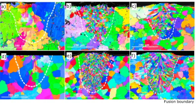
Aside from controlling the grain size and morphology, manipulation of the heat source can be used to texture the material in different regions of interest. As exemplified inFig. 11 [160], it is possible to locally change the grain orientation at precise locations in the as-built part. The manipulation of the heat source enabled to create specific scan strategies, which allowed to consider the heat source as a point or a line, as desired. As a result, the thermal gradient in the melt pool as well as the liquid/solid interface stability change, grains grown with preferential orientation. The innovative aspect of this work was the intentional modification of the grain orientation is specific locations of the part.
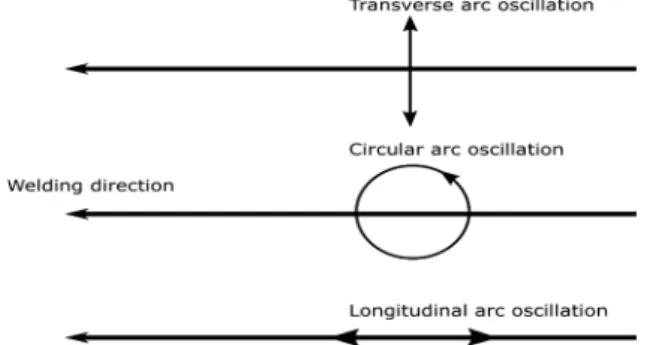
4.1.2. Heat source control via magnetic oscillation
Another way to manipulate the heat source is trough magnetic oscillation and this can be only applied in arc-based processes. Basically, a magnetic oscillator will cause the electrical arc to move in the transverse, circular or longitudinal direction relatively to the welding direction, as schematically shown inFig. 12. As it will be shown, the type of movement enabled by the magnetic oscillation will impact differently in the generated microstructures of the fusion zone.
Magnetic arc oscillation for microstructural refinement of the fusion zone was nicely exemplified by the works of Kou’s group [122,125,161]in gas tungsten arc welding of Al and Mg alloys. Parameters of interest during magnetic arc oscillation include the amplitude of oscillation, whose maximum is typically equal to the arc length, and frequency of oscillation. Oscillation of the arc during welding is effective in modifying the grain orientation in the fusion zone[125]. This is especially important for alloys that are prone to solidification cracking: because it is intergranular, the existence of multiple grain orientations within the fusion zone cause the crack to deflect periodically, thus its propagation is hampered. It must be noticed however, that the combination of the oscillation movement and frequency has a critical role in decreasing solidification cracking in fusion welds: for the transverse and circular arc movements at low frequency (≈ 1 Hz) grain refinement and reduction of solidification cracking phenomena occurred; whereas for the longitudinal arc movement, only at high frequency (> 25 Hz) the same effect was noticed.
Fig. 10. Effect of thermal gradient and solidification rate on the columnar-to-equiaxed transition during laser-based additive manufacturing (adapted from[99]).
Though arc oscillation can effectively promote grain refinement in the fusion zone its effect is dependent on the alloy compo-sition, since some alloys are known to be more prone to form columnar than equiaxed grains. For example, in AZ31 Mg alloys, it has been shown that equiaxed grains can grow into columnar ones, while such has not been observed for AZ91 Mg alloys[122]. This tendency for the grains to growth into columnar or equiaxed morphologies can be further manipulated by the controlled addition of alloying elements that can provide extra constitutional supercooling. For Mg alloys, the controlled addition of Al increases con-stitutional supercooling, allowing that small solid particles that exist within the fusion zone are not remelted and grow into an equiaxed structure.
It must be noticed that despite most of the works that use arc oscillation require an external magnetic oscillator, a similar arc movement can also be achieved using mechanical oscillators[162]. Similar refinement effect can be achieved, provided that the oscillation amplitude and frequency operate within a suitable range.
The use of magnetic arc oscillation during additive manufacturing can be highly effective in promoting grain refinement, though it has not been used yet. It is likely that the most effective arc movements during arc-based additive manufacturing are transverse and circular oscillation, following the observations made during arc-welding of Mg and Al alloys by Kou et al.[122,125]. The relevance of using either transverse or circular arc movements arise from three different effects: (i) it can ensure that during subsequent material depositions there is an actual overlap between adjacent beads, which can prevent defects such as lack of fusion and pores; (ii) it can provide lower cooling rates, which mitigate residual stresses, though the formation of non-desired precipitates may occur; (iii) because of the non-continuous movement of the arc, it is possible to promote detachment of previously solidified material from the partially melted zone (solid + liquid domain in a phase diagram), which, combined with the fluid flow enhanced by the arc movement, can promote grain refinement via dendrite fragmentation[42,54,122]. Dendrite fragmentation occurs due to the annular flow in the liquid metal along the solidification front. The solid fragments, are not melted again in the melt pool, will provide extra nucleation points, thus promoting grain refinement. However, arc oscillation during arc-based additive manufacturing may not be used for building single walls, unless longitudinal oscillation is used. This is related to the fact that arc-based additive manufacturing processes have poor dimensional accuracy and the use of circular or transverse arc oscillation will increase the width of each deposited layer.
4.2. Adjustment of operating procedures 4.2.1. In welding
The adjustment of operating procedures during welding, namely the control of the arc voltage, current intensity and type (AC/DC and/or pulsed/continuous), welding power, welding speed and protective gas are fundamental not only to modify the microstructure of the fusion zone but also its geometry, that is, width and depth of the molten pool. Furthermore, the control of these parameters can be used to gain better process stability.
Fig. 11. Inverse pole figure orientation maps on the cross-section of a Ni-based superalloy fabricated using powder-bed electron beam additive manufacturing (from[160]).
In welding, the ratio between the welding power and the welding speed defines the heat input. The heat input is eventually the most important parameter during fusion welding since it gives a qualitative estimate on the cooling rate and extension of the fusion zone. For example, fixing the welding process and the material to be joined, it is known that higher heat input leads to lower cooling rates and to a higher extension of the fusion zone.
Additionally, the heat input introduced during welding impacts distortions due to the large volume of material melted and that shrinks during solidification. In particular, arc-based welding techniques have associated higher heat input than those in high power beam (laser and electron beam) techniques. This is one of the reasons why laser or electron beam welding are less prone to distortion during welding.
The cooling rate is of special importance during fusion-based welding since it controls the solidification mechanisms, solid-state transformations and residual stresses. Therefore, the control of the heat input during welding is of major importance as referred in Section 2and in multiple research works[62,163–170].
During gas tungsten arc welding of 304 stainless steel, Kumar et al.[171]reported that the heat input selection had all the aforementioned consequences: higher heat input lead to a greater extension of the fusion and heat affected zones. Additionally, the average dendrite length and interdendritic spacing, which give an indication of the solidification conditions, increased with in-creasing heat input due to a lower cooling rate experienced by the material. Another research work on arc welding of 304 stainless steel[172], reported that increasing heat input resulted in a higher volume fraction of ferrite in the fusion zone, pointing the need to carefully control the heat input to promote or avoid solid-state transformations upon cooling.
The selection of the heat input, and therefore of the cooling rate, indirectly controls the segregation phenomena in the weld pool, and, since it facilitates the formation of liquid films of low melting point along the grain boundaries it can affected cracking sus-ceptibility. Therefore, control of the heat input is fundamental in materials that experience hot cracking, such as Ni alloys and austenitic stainless steels.
One important difference that exists between welding and additive manufacturing is that in the former mechanical constraints are typically used. As a result of these mechanical constraints, the material is not able to freely expand and contract during the weld thermal cycle and significant residual stresses, and distortions, can occur. The effect of mechanical constraints during welding has been studied by[173]. When no mechanical constrains were used a decrease in both the transverse and longitudinal residual stresses was measured. During additive manufacturing the absence of highly restrictive mechanical constrains can allow for the material to better accommodate the thermal stresses during multiple thermal cycles experienced. However, up to now no significant detailed studies of the development of residual stresses during fusion-based additive manufacturing are available. It must be noticed however, that the constant heat and cooling experienced during sample build-up and the prolonged times at higher temperatures during wire and arc additive manufacturing can act to promote an in-situ stress relieve heat treatment which can lower previously developed residual stresses. However, in large parts built by wire and arc additive manufacturing, mechanical constraints are usually imposed and residual stresses are added up, so distortions can be significant and post-production heat treatment may be required.
The control of the heat input is also of major importance for alloys that are prone to liquation cracking. This defect occurs in the partially melted zone when the liquated material solidifies. Such type of cracking can occur in both welding and additive manu-facturing where fusion occurs, since the thermal cycle experienced by the material in both cases will promote partial liquation at the fusion boundary. For example, Aluminum alloys with high freezing temperature range, such as AA 7075, are prone to liquation cracking. By increasing the heat input the amount of liquated material is higher and the probability for liquation cracking to occur drastically increases as exemplified in[174,175]. For this reason, decrease of the heat input, which can be performed by multipass arc-welding or by high power beam welding, is of paramount importance.
During multipass welding of steels, temper bead welding is often used to control the microstructure and toughness of the de-posited material and its surroundings. When temper bead welding is correctly applied it is possible to temper the already solidified material by controlling the heat input[176]. Parameters of interest to control the temper bead technique include the heat input, which will control the thermal cycle but also the bead overlap. Depending of the steel that is to be welded, thickness and hardness tolerance for the desired application, the heat input selection and bead overlap can greatly differ between different arc welding techniques[177]. The final deposited material will have a higher hardness than that previously deposited, since this last welding pass does not experience any tempering[178].
Temper bead technique can be useful for the creation of large parts via arc-based additive manufacturing, though this has not yet reported. One potential issue that may arise from using temper bead during additive manufacturing is related to the bead overlap, or hatch distance as commonly referred in additive manufacturing. Typically, the required bead overlap for successful temper bead is above 50%, which can be detrimental to the process productivity. On the other hand, arc-based techniques have high production rates. Hence, it is possible that the ability for in-situ microstructural control enabled by temper bead technique during arc-based additive manufacturing can surpass the lower production times associated with the high bead overlap required.
The control of the interpass temperature during multipass welding is another welding operating procedure that needs to be carefully controlled to optimize the microstructure and mechanical properties of welded joints. This is common in multipass welding of steels[179]. Residual stresses are known to develop as a result of the weld thermal cycle. In steels, martensite can easily fracture as a result of these thermal residual stresses. However, if each welding pass is performed so that the temperature of the already deposited material is above the martensitic start transformation temperature, then the weld deposit will be composed of austenite and/or ferrite, which can sustain higher residual stresses without the development of cracks. Once the weld is completely performed, post-weld heat treatments can be applied to decrease the residual stress and improve the joint mechanical properties. It must be noticed that the interpass temperature directly depends on the thickness of materials to be deposited, heat input, environmental conditions and heat transfer.
![Fig. 3. Schematic representation of the effect of temperature gradient and growth rate on the solidification microstructures (from [1]).](https://thumb-eu.123doks.com/thumbv2/123dok_br/15709291.1068687/6.816.253.561.735.1009/schematic-representation-effect-temperature-gradient-growth-solidification-microstructures.webp)

![Fig. 7. Effect of multipass welding on the temperature profile in the heat affected zone of a low carbon steel (from [67]).](https://thumb-eu.123doks.com/thumbv2/123dok_br/15709291.1068687/8.816.252.564.78.288/effect-multipass-welding-temperature-profile-affected-carbon-steel.webp)
![Fig. 9. Schematic representation of different gradient structures which can be created by additive manufacturing (from [91]).](https://thumb-eu.123doks.com/thumbv2/123dok_br/15709291.1068687/10.816.165.656.724.1014/schematic-representation-different-gradient-structures-created-additive-manufacturing.webp)
![Fig. 10. Effect of thermal gradient and solidification rate on the columnar-to-equiaxed transition during laser-based additive manufacturing (adapted from [99]).](https://thumb-eu.123doks.com/thumbv2/123dok_br/15709291.1068687/14.816.251.565.746.995/effect-gradient-solidification-columnar-equiaxed-transition-additive-manufacturing.webp)
![Fig. 13. Change in hardness (a) and volume fraction of α 2 phase (b) as a function of interlayer temperature during wire and arc additive manu- manu-facturing of a γ-TiAl alloy (adapted from [202]).](https://thumb-eu.123doks.com/thumbv2/123dok_br/15709291.1068687/18.816.249.568.488.1000/change-hardness-fraction-function-interlayer-temperature-additive-facturing.webp)