University of Aveiro
2014
Department of Materials Engineering and Ceramic
Daniel Eduardo
Loureiro Vieira
Active protective treatments for galvanically
coupled AA2024 and CFRP
Dissertation submitted to the University of Aveiro to fulfill the requirements for obtaining a Master's degree in materials engineering, held under the scientific guidance of Dra. Maria Serdechnova, post – doctoral researcher at the Department of Ceramic and Materials Engineering at the University of Aveiro and Dr. Mikhail Zhelukedvich invited associate professor in the Department of Ceramic and Materials Engineering at the University of Aveiro.
The jury Doctor José Filipe Alves de Oliveira
Assistant researcher in Department of Ceramic and Materials Engineering at the University of Aveiro.
Doctor Sviatlana Valeriana Lamaka
Assistant researcher in Institute of Materials and Surfaces Science and Engineering at Technical University of Lisbon
Doctor Maria Vladimirovna Serdechnova
Post – doctoral researcher in the Department of Ceramic and Materials Engineering at the University of Aveiro
Acknowledgements
A big thank you to my family and girlfriend for all the moral support and patience throughout the course and in particular over the last year because without them everything would have been much more complicated.A huge thank you to the University of Aveiro and the Airbus group for having given me this gigantic opportunity to intern at one of the world's largest companies, especially to Dr. Mikhail Zhelukedvich and Mr. Theo Hack for they have put their trust in me and gave me the possibility to perform the internship and work in PROAIR project.
Other huge thanks to my advisor Dra. Maria Serdechnova for everything you taught me, all the patience to explain and to correct errors, for all the fun times offered, once again thank you very much.
A thank you to all my colleagues at Airbus group for all the good times provided in the company, in particular to Sonja Nixon throughout the patience to explain and help when needed.
I am also grateful to my laboratory colleagues at the University of Aveiro, in particular, Pedro Moreira and MsC. André Oliveira, to Dr. Alexandre Bastos, Dr. Andrei Salak and Dr. Silvar Kallip by all teachings transmitted and all the help you have provided during this year because even with a lot of work they always had a little time to help when needed.
And last but not least, I thank all my colleagues and friends for all the great and happy moments we have during the academic career and a special thank you to Marco Oliveira and Alexandre Rocha for listening and sharing ideas in this final stage of master's thesis.
Resumo No presente trabalho revestimentos "inteligentes" foram sintetizados com a finalidade de proteger contra a corrosão a liga de alumínio AA2024 acoplada galvanicamente com a fibra de carbono reforçado com plástico (CFRP). Os nanocontentores LDH Mg/Al LDH e Zn/Al LDH foram carregados com os inibidores orgânicos 2-mercaptobenzotiazole e 1,2,3-benzotriazole, e com inibidores inorgânicos metavanadato, tungstato e molibdato. No caso dos nanocontentores de bentonite o inibidor incorporado foi o Ce(NO3)3.
A análise por difração de raios-X (DRX) e microscopia eletrónica de varrimento (MEV) foram realizadas a fim de caracterizar os nanocontentores obtidos.
Os nanocontentores foram aplicados em revestimento epóxi na superfície do sistema modelo (AA2024 galvanicamente acoplado com CFRP), os LDH’s preenchidos com inibidores em mistura com Ce3+ carregado na bentonite foram usados com o objetivo de aumentar as propriedades de proteção do revestimento contra a corrosão. As análises das propriedades anticorrosivas dos revestimentos foram realizadas utilizando o ZRA (Zero resistance ammeter), espectroscopia de impedância eletroquímica (EIS), microscopia ótica, teste de nevoeiro salino (SST) e SVET (scanning vibrating electrode technique).
O trabalho foi realizado em ambiente laboratorial e posteriormente em ambiente industrial (Airbus group).
Palavras - chave Revestimentos intelegentes, inibidores, nanocontentores, protecção contra corrosão.
Abstract In the present work “smart” nanocontainers were synthesized in order to incorporate them into an organic coating and protect against corrosion of the aluminum alloy (AA2024) galvanically coupled with carbon fiber reinforced plastic (CFRP). The containers were loaded with organic (2-mercaptobenzothiazole and 1,2,3 – benzotriazole) and inorganic (metavanadate, tungstate and molybdate) inhibitors in the case of Mg/Al and Zn/Al LDH nanoreservoirs. In the case of the bentonite nanocontainers, the containers were loaded with Ce(NO3)3. X-ray diffraction (XRD) and scanning electron microscopy (SEM) analyses were performed in order to characterize the obtained nanocontainers.
The nanocontainers were enbeded into epoxy coating on the surface of model multi-material system (AA2024 galvanically coupled with CFRP). The LDHs loaded with different inhibitors and combined with bentonite loaded with Ce3+, increase the anticorrosion protection properties of the coating. The analyses of the anticorrosion properties of the coatings were performed using zero resistance ammetry (ZRA), electrochemical impedance spectroscopy (EIS), optical microscopy, salt spray test (SST) and scanning vibrating electrode technique (SVET) measurements. The laboratory work was realized in University of Aveiro in collaboration with industrial environment of Airbus group.
Key-words Smart self – healing coatings, inhibitors, nanocontainers, corrosion protection
Abstrakt In der vorliengen Arbeit wurden die “intelligenten”
Nanocontainers zum Schutz gegen Korrosion der
Aluminiumlegierung AA2024, galvanisch mit Kohlefaserstarktem Kunststoff (CFK) gekoppelt, synthetisiert. Die Containers wurden mit Bio-(2-Mercaptobenzothiazol und 1,2,3-Benzotriazol) und anorganischen (Metavanadat, Wolframat und Molybdat) Inhibitoren , wenn Mg/Al und Zn/Al-LDH nanoreservoirs wurden angevendet , und Ce(NO3)3, wenn Bentoniten Nanocontainers wurden angevendet, geladen. Rontgenbeugung (XRD) und Rasteretektronenmikroskopie (SEM)-Analysen wurden durchgefuhrt, um die erhaltenen Nanocontainers kennzeichnen. Die LDHs wurden in Epoxidüberzug auf der Oberflache des Modells Multi-Material-System (AA2024 galvanisch mit CFK-gekoppelt) aufgetragen, mit Inhibitoren in Mischung mit Ce3+ in Bentonit geladen, erhohen die Korrosionsschutzeigenschaften der Beschichtungen. Die Analysen der Korrosionsschutzeigenschaften der Beschichtungen wurden mittels Null-Widerstand Ampermeter (ZRA), electrochemishe Impedanzspectroskopie (EIS), optische Mikroskopie, Salzspruhtest (SST) und Raster vibrierenden Electrodentechnik (SVET) - Messungen durchgefuhrt. Die Arbeit im Labor wurde in der Universitat von Aveiro in Zusammenarbeit mit industrillen Umfeld in AirbusGruppe (Deutschland) leistet.
Schlüsselworte “intelligenten” selbstheilende Beschichtungen, Inhibitoren,
Content
List of abbreviations ... XIII Figure content ... XV Table content ... XIX
1. Introduction ... 1
1.1. Basics of protection with coatings ... 2
1.1.1. Corrosion processes ... 2
1.1.2. Typical protection mechanisms ... 3
1.1.3. Barrier protection ... 3
1.1.4. Galvanic protection ... 4
1.1.5. Inhibitors ... 4
1.1.6. Multi-layer construction ... 7
1.2. Materials of the aeronautic industry ... 7
1.2.1. Aluminum ... 7
1.2.2. Role of pH for the aluminum corrosion ... 8
1.2.3. Role of chloride for aluminum corrosion ... 9
1.2.4. Carbon fiber reinforced plastic ... 9
1.3. Objective of the work ... 10
2. Experimental procedure and conditions used ... 12
2.1. Materials used ... 12
2.2. Type of coatings ... 12
2.3. Techniques ... 12
2.4. Samples and sample holder used ... 15
2.6. Inhibitors intercalation ... 19
2.7. Synergistic mixtures ... 20
3. Results ... 22
3.1. Research laboratory ... 22
3.1.1. Nanocontainer characterization ... 22
3.1.2.Results of the different types of coated formulations ... 24
3.2. Industrial results ... 41
3.2.1. X-ray diffraction (XRD) ... 41
3.2.2. Electrochemical tests ... 44
4. Discussion ... 72
4.1.Sample holder ... 72
4.2. Protection with inhibitors ... 72
4.3. Inhibition efficiency ... 76 4.4. EIS improvement... 77 4.5. Synergistic effect ... 78 4.6. SVET ... 79 5. Conclusions ... 81 6. Bibliography ... 83
List of abbreviations
CFRP - Carbon fiber reinforced plastic; AA2024 - Aluminum alloy 2024; LDH - Layered double hydroxides; SST - Salt spray test;
EIS - Electrochemical impedance spectroscopy; ZRA - Zero resistance ammeter;
SEM - Scanning electron microscopy;
SVET - Scanning vibrating electrode technique; XRD – X – Ray diffraction;
MBT – 2-mercaptobenzothiazole; BTA – 1,2,3 – benzotriazole; IE – Inhibitors efficiency.
Figure content
Figure 1 - Corrosion around: airplanes, cars and bridges ... 1
Figure 2 - Different mechanisms of corrosion protection ... 3
Figure 3 - Schematic presentation of 2-mercaptobenzothiazole and 1,2,3-benzotriazole molecules. ... 5
Figure 4 - Multilayer construction ... 7
Figure 5 - Carbon fiber for CFRP ... 9
Figure 6 - Materials breakdown for Airbus A350 aircraft... 11
Figure 7 - SVET equipment... 14
Figure 8 - Sample used for electrochemical tests in Aveiro University ... 15
Figure 9 - Aluminum and CFRP Samples used in Airbus group ... 15
Figure 10 - Sample holder used in Airbus group ... 16
Figure 11 - Sample holder with the wires and the sealant already applied. ... 17
Figure 12 - LDH Synthesis ... 18
Figure 13 - Inhibitors intercalation ... 20
Figure 14 - SEM images for the different types of nanocontainers, used in this work ... 22
Figure 15 - The XRD patterns of Mg/Al LDH before and after intercalated with BTA and MBT ... 23
Figure 16 - XRD of Zn/Al LDH loaded with MBT ... 24
Figure 17 - Corrosion test for different types of coating ... 25
Figure 18 - EIS for reference sample without scratch and scratched. ... 27
Figure 19 - EIS for Reference sample and Tungstate loaded into Mg/Al LDH mixed with Ce3+ loaded into bentonite. ... 27
Figure 20 - EIS analyses for MBT loaded into Mg/Al LDH mixed with Ce3+ loaded into bentonite, MBT loaded into Mg/Al LDH. ... 29
Figure 21 - EIS analyses for BTA loaded into Mg/Al LDH mixed with Ce3+ loaded into bentonite, Ce3+ loaded into bentonite. ... 29
Figure 22 - EIS analyses for Metavanadate loaded into Mg/Al LDH mixed with Ce3+ loaded into bentonite, metavanadate loaded into Mg/Al LDH. ... 30
Figure 23 - EIS analyses for Tungstate loaded into Mg/Al LDH mixed with Ce3+ loaded into bentonite, tungstate loaded into Mg/Al LDH. ... 30
Figure 25 - SVET measurement from coating formulation molybdate loaded into Mg/Al
LDH mixed with Ce3+ loaded into bentonite ... 37
Figure 26 - Maximum and minimum peaks of corrosion ... 38
Figure 27 - Corrosion currents calculated through “Total current” for Tungstate loaded into Mg/Al LDH mixed with Ce3+ loaded into bentonite, Tungstate loaded into Mg/Al LDH and Reference. ... 39
Figure 28 - Corrosion currents calculated through “Total current” for MBT loaded into Mg/Al LDH mixed with Ce3+ loaded into bentonite, MBT loaded into Mg/Al LDH and reference. ... 40
Figure 29 - Total current during 24 hours between MBT loaded into Mg/Al LDH mixed with Ce3+ loaded into bentonite and tungstate loaded into Mg/Al LDH mixed with Ce3+ loaded into bentonite. ... 40
Figure 30 - XRD pattern of BTA intercalated into Mg/Al LDH ... 41
Figure 31 - XRD pattern of MBT intercalated into Mg/Al LDH ... 42
Figure 32 - XRD pattern of vanadate intercalated into Mg/Al LDH... 42
Figure 33 - XRD pattern of Mg/Al LDH intercalated with molybdate ... 43
Figure 34 - XRD pattern of Mg/Al LDH loaded with tungstate. ... 43
Figure 35 - Old Reference ... 44
Figure 65 - Different types of coating application ... 45
Figure 36 - ZRA measurements of all samples ... 45
Figure 37 - ZRA analyses in percentage of efficiency for all samples ... 46
Figure 38 - Reference coating without any inhibitors ... 47
Figure 39 - Equivalent circuit used during the measurements ... 48
Figure 40 - Equivalent circuit after the formation of artificial scratch ... 48
Figure 41 - The EIS spectra obtained from galvanically coupled AA2024 and CFRP coated with epoxy coating containing mixture of MBT loaded into Mg/Al LDH and Ce3+ loaded into bentonite. ... 49
Figure 42 - The EIS spectra obtained from galvanically coupled AA2024 and CFRP coated with epoxy coating containing mixture of BTA loaded into Mg/Al LDH and Ce3+ loaded into bentonite ... 50
Figure 43 - The EIS spectra obtained from galvanically coupled AA2024 and CFRP coated with epoxy coating containing mixture of metavanadate loaded into Mg/Al LDH and Ce3+ loaded into bentonite ... 50 Figure 44 - The EIS spectra obtained from galvanically coupled AA2024 and CFRP coated with epoxy coating containing mixture of tungstate loaded into Mg/Al LDH and Ce3+ loaded into bentonite ... 51 Figure 45 - The EIS spectra obtained from galvanically coupled AA2024 and CFRP coated with epoxy coating containing mixture of molybdate loaded into Mg/Al LDH and Ce3+ loaded into bentonite ... 51 Figure 46 - Comparison of EIS results for a1) 1 hour without scratch, a2) 24 hours without scratch, b1) 1 hour with scratch and b2) 24 hours with scratch, for the different coating formulations ... 52 Figure 47 - Photos of the corroded reference sample during the immersion test ... 53 Figure 48 - Photos of the corrosion processes of the sample coating the mixture of inhibitors (MBT loaded into Mg/Al LDH together with the Ce3+ loaded into bentonite) ... 54 Figure 49 - Photos of the corrosion processes of the sample containing the mixture of inhibitors (BTA loaded into Mg/Al LDH together with Ce3+ loaded into bentonite) ... 55 Figure 50 - Photos of the corrosion processes of the sample containing the mixture of inhibitors (metavadate loaded into Mg/Al LDH together with Ce3+ loaded into bentonite) 56 Figure 51 - Photos of the corrosion processes of the sample containing the mixture of inhibitors (Tungstate loaded into Mg/Al LDH together with Ce3+ loaded into bentonite) . 57 Figure 52 - Photos of the corrosion processes of the sample containing the mixture of inhibitors (molybadate loaded into Mg/Al LDH together with Ce3+ loaded into bentonite) ... 58 Figure 53 - 200x times magnification of the corroded zone of aluminum after 24h of immersion ... 58 Figure 54 - Photos of all samples with different mixtures of inhibitors into the coating formulation after 48 hours of immersion ... 59 Figure 55 - Photos of AA2024 aluminum alloy protected by coating containing mixture of inhibitors into the formulation after 24 hours of SST ... 61 Figure 56 - Photos of AA2024 aluminum alloy protected by coating containing mixture of inhibitors into the formulation after 48 hours of SST ... 62
Figure 57 - Photos of AA2024 aluminum alloy protected by coating containing mixture of
inhibitors into the formulation after 72 hours of SST ... 62
Figure 58 - “Zone1” (near CFRP) and “Zone 2” ( about 4 mm from CFRP) ... 63
Figure 59 - Photos of galvanically coupled AA2024 and CFRP after 4 hours in SST ... 64
Figure 60 - General view of the sample after 48 hours in SST ... 67
Figure 61 - EIS results for 24 hours of immersion test and after 72 hours of SST ... 70
Figure 62 - Results from SST after 24 hours with new scratch applied ... 71
Figure 63 - Anion exchange reaction occurred with LDHs during corrosion protection .... 73
Figure 64 - The schematic presentation of the chemisorbed layer formed by BTA ... 73
Table content
Table 1 - pH used for intercalation of different inhibitors into Mg/Al LDH ... 19
Table 2 - Synergistic mixtures produced in Aveiro University and Airbus Group. ... 21
Table 3 - Times needed to corrosion starts for samples with different coatings ... 26
Table 4 - SVET map’s for different types of coating formulation, using MBT as inhibitor protection ... 34
Table 5 - SVET map’s for different types of coating formulation using tungstate as inhibitor protection ... 35
Table 6 - Maximum and minimum average of the corrosion peaks and average total currents ... 36
Table 7 - Photos of galvanically coupled AA2024 and CFRP after 24 hours of SST... 65
Table 8 - Photos of galvanically coupled AA2024 and CFRP after 28 hours of SST... 66
Table 9 - Photos of galvanically coupled AA2024 and CFRP after 48 hours of SST... 67
Table 10 - Photos of galvanically coupled AA2024 and CFRP after 72 hours of SST ... 68
1. Introduction
Metals and metallic alloys are currently widely used in different engineering applications. Consequently, corrosion is a big issue in the most engineering infrastructures (examples are in Figure 1) [1].
Figure 1 – Corrosion around: airplanes, cars and bridges
An innovative idea to corrosion mitigation is the use of active “smart” self-healing anti-corrosion protective coating [2,3]. These “smart” coatings are able to release inhibitors and prevent corrosion only when they are triggered by a stimulus linked to onset of corrosion processes.
The main objective of this work is the development of new protective self-healing coatings for aeronautic application where the material degradation can cause dramatic aftermaths not only for the used constructions but also for human lives.
Which materials are currently under interest for the aeronautic applications? 1. Light materials like aluminum alloys are well-known materials with good
mechanical properties [4]: low weight, good corrosion resistance and relatively lower price in comparison with many other metals.
2. Carbon fiber reinforced plastic (CFRP) is a novel composite material, with extremely promising properties like high strength-to-weight ratio, and conductive properties [5].
The problem appears when these conductive materials are used in the electrical contact (requirement of thunderstorm protection). The more noble CFRP induces the extremely accelerated corrosion of aluminum due to galvanic coupling. To avoid this problem and prolong the life-time of proposed model system (aluminum alloy connected to
CFRP) a new active self-healing materials is going to be developed and applied in frame of this master project (performed in frame of PROAIR project for aeronautic industry).
1.1. Basics of protection with coatings 1.1.1. Corrosion processes
Corrosion of metals can be defined as the destructive attack of a metal through its interaction with environment [6]. It is a complex phenomenon which can occur into very different solutions [7]. Electrochemical corrosion is the most frequent nature of the chemical corrosion; usually it happens by the direct contact of the metal with the aggressive corrosive environment.
The electrochemical corrosion is normally characterized by the presence of aqueous solution in contact with the metal, thus providing an electrochemical system with movement of electrons near the metal surface and occurrence of the oxidation-reduction reactions at the respective electrodes. The most important dissolution of metal under these conditions can be presented by anodic reaction of metal oxidation:
M - ne-→ Mn+ (1)
where M is the original metal, Mn+ is oxidized metal (can be in form oxide/hydroxide which represents the rust on the surface) and n are the number of electrons involved into the reaction (1) [6].
The cathodic reaction during the corrosion processes can be presented as reduction of hydrogen (reaction 2), oxygen (reaction 3) or water (reaction 4):
2H+ +2e- → H2 (2)
O2 + 2H2O +4e-→ 4OH- (3)
2H2O + 2e- → H2 + 2OH- (4)
The reaction (2) occurs mainly in acidic media with low O2 concentrations. The reaction (3) occurs preferably when high concentration of O2 is available. The reaction (4) occurs in neutral or basic medium. The corrosion reactions may be accelerated by an increase of temperature, by increase amounts of oxidants (like oxygen), in high concentrations of corrosive species (like Cl-), etc [6].
According to these reactions the cathodic area will be characterized by the increase of the pH near the metallic surface and into the solution around.
1.1.2. Typical protection mechanisms
For a better understanding of basics of protection for the substrate by coatings, possible types of corrosion protection should be mentioned. Commonly, the corrosion protection can be divided in three different types (Figure 2) [1,2,8]:
1. The barrier protection by the paint, which limits the transport of water and aggressive species to the metallic surfaces;
2. The sacrificial protection by active metal which present as a metal coating or as a pigment;
3. The protection by inhibitors (additives) which released during the contact of the coating with the environment.
Figure 2 - Different mechanisms of corrosion protection
Moreover, all these types of protective coatings can be used in a multi-layer construction [9]. For example, the barrier protection is not sufficient in the presence of defects and on cut-edges, but it still can modify the active coating reactivity. Protective properties may be improved by galvanic protection or the use of inhibitors.
For better understanding, we will review the basic approaches for each protective mechanism separately.
1.1.3. Barrier protection
Barrier protection is typically offered by organic paints. The barrier coatings are used to suppress the corrosion reaction by limiting the diffusion of the electrolyte, oxygen
transport of electrons to the metal interface [2], suppressing the corrosion reactions. The weak point of the barrier protective coatings is the possible defect formation: as soon as the coating has any scratches, it stops being effective.
1.1.4. Galvanic protection
The second type of the protection, particularly important in the presence of defects in the coating, is the sacrificial protection by the more active metal. The sacrificial material for corrosion protection must have the following attributes [2]:
(1) Excellent electrical contact,
(2) A suitable electrochemical potential relative to the material, that is going to be protected,
(3) Formation of suitable corrosion product layer(s) [10].
The possibility of magnesium (Mg) application for active galvanic protection of aluminum was reported [11]. In theory this can be a good solution however the main limitation of this method is the fire hazard associated to Mg metal, especially when it is used in form of powder [11]. In the case of aircrafts it is not sufficient.
1.1.5. Inhibitors
The protection with inhibitors was chosen in the frame of this master project. For several decades the most used anti-corrosion inhibitor for aluminum in the presence of halide ions [12] was CrO42-. Its action is still not completely understood but it is generally attributed to the formation of an oxide film on the metal surface (reaction 5), preventing the corrosion [12].
Cr2O72- + 8H+ + 6e+ = 2Cr(OH)3 + H2O (5)
The necessity to exclude chromates from the surface treatment procedure has dramatically affected the aerospace industry due to its dependence on the use of aluminum based alloys in aircraft manufacturing. In order to replace chromate inhibitors, both organic and inorganic inhibitors were proposed [12].
1. Organic inhibitors. Although the mechanisms of protection with organic inhibitors are not completely understood, the basic principle associated with them is the adsorption of
prevent the contact between material and aggressive environment, leading to the decrease of corrosion activity [13].
Previous work with 2–mercaptobenzothiazole (MBT, Figure 3-a) and 1,2,3– benzotriazole (BTA, Figure 3-b) [6] has shown effective inhibition for galvanically coupled Al alloy with more noble material like steel or copper [8,14].
Figure 3 – Schematic presentation of 2-mercaptobenzothiazole (a) and 1,2,3-benzotriazole (b) molecules.
2. Inorganic inhibitors. As an alternative to organic inhibitors, some inorganic inhibitors have also been proposed for Al alloys. These inhibitors are cerium [2], lanthanum [6], molybdates [6], vanadates [6], phosphates [6] and silica-based inhibitors [2]. In previous work with cerium based inhibitors it was shown that this inhibitor creates a passive insoluble oxide layer that stops the oxygen diffusion from the aggressive environment to the surface [6, 15].
3. Synergistic mixture. In order to create a more effective inhibition system, mixtures of inhibitors have been used [6, 16, 17]. It was shown that the inhibiting actions of two compounds were not always additive: mutual increases or decreases in the inhibition effect were often observed [14]. For example, it was reported that a mixture of inhibitors (BTA + Ce3+) is much more effective for protection of galvanic coupled (Zn+Fe) in comparison with the independent inhibition by BTA or Ce3+ compound [6].
For the effective protection of the material with an inhibitor, the easy access of the inhibitor to the surface is desirable. Originally, inhibitors were directly applied into the coating [6]. However, being applied directly, they could interact with the material of the coating and accelerate is destruction [18]. Due to this destruction the ability to keep inhibitors in the coating decreases. It leads to the loss of the inhibitor, decrease of the inhibition activity and possibly creates problems for people and for the environment.
In line with the idea of using environmentally friendly materials and processes, it is necessary to find a solution for controlling the release of the inhibitors. Two types of “smart” nanocontainers are promising for this aim: layer double hydroxides (LDH) [2] and bentonite [2].
These nanocontainers are able to keep the inhibitors inside their structure and to prevent the contact between them and the coating; moreover the inhibitor release takes place only when the container is triggered.
4. Layered double hydroxides (LDH) are hydrotalcite-like compounds [2]. LDHs are known as a good anion-exchangers [19]. Between two positively charged layers of metallic cations/hydroxides there are negatively charged layers of anions. Using the LDH capability to anionic exchange some inhibitors, like MBT or BTA, could be included into the structure in anionic form.
When LDH is loaded with inhibitors and inserted into the coating structure, it is placed near a metallic surface. When the substrate starts to corrode, the anions-exchange capability of LDH is used again: inhibitors are replaced by OH-, formed by the cathodic reaction of water reduction, or by chloride anions available from the aggressive media. It leads to two advantages of LDH: controlled release of the inhibitor only when corrosion starts and absorbance of cathodically formed hydroxides, what is especially critical in case of aluminum corrosion.
5. Bentonite is a cation-exchanger, consisting of negatively charged alumosilicate sheets, between which inhibiting cations can be intercalated [2, 20] Ce3+ loaded bentonite is promising to be dispersed in epoxy resin layers and to be applied to surface of coupled materials for the active anti-corrosion protection. The release of the inhibitor is triggered by metal cations available in the surroundings. In the case of the corrosion reaction of coupled aluminum alloy and CFRP the role of external cations can play Na+ as a corrosion agent or Al3+ released from the material during its degradation.
Ce3+ is well-known as a corrosion inhibitor [2, 21, 22]. The effective inhibition happens because of the reaction between Ce3+ and hydroxides which leads to the formation of insoluble hydroxide [2]:
The further oxidation of Ce(OH)3(s) leads to the formation of CeO2 according to the reaction (7). This compound is also insoluble and prevents the contact of the surface with aggressive environment [2].
4Ce(OH)3+O2 → 4CeO2+6H2O (7)
1.1.6. Multi-layer construction
The most effective corrosion protection can be achieved by a combination of different protective mechanisms in the case of galvanically coupled aluminum alloys and CFRP, the barrier protection by organic or inorganic polymer (and corrosion products [9] and protection with inhibitors (Figure 4).
Figure 4 -Multilayer construction
1.2. Materials of the aeronautic industry 1.2.1. Aluminum
Aluminum alloys are well-known materials with good mechanical properties, low densites, good corrosion resistance and lower price in comparison with many other metals. They are widely used in many engineering applications and scientific technologies, such as aerospace, advanced nuclear reactor, surface coating, metal/air batteries, medicine, etc. [18,4,23].
The surface of aluminum (Al) is covered by a natural insoluble passive film [18]. It leads to a very low reactivity and corrosion rate of Al under neutral aqueous conditions. However, the presence of more noble components in electrical contact with aluminum accelerates its corrosion due to galvanic coupling [12]. It causes degradation of the material and accumulation of corrosion products which leads to the a reduction of the mechanical
properties. To avoid these unwanted processes, the fundamental mechanism of aluminum reactivity must be carefully understood.
1.2.2. Role of pH for the aluminum corrosion
The pH has an important role for the aluminum corrosion: the thin protective insoluble aluminum oxide is present on the surface of material only in the pH range between 4.0 and 8.5. When the pH reaches 10 or decreases below 4 the dissolution of aluminum oxide starts according to the reactions (8) and (9) respectively.
Al2O3(surf) + 2OH- + 3H2O → 2Al(OH)4-(aq) (8) Al2O3(surf) + 6H+ → 2Al3+(aq) + 3H2O (9)
The formation of hydroxides near the surface of aluminum takes place due to the cathodic reaction of water or oxygen reduction by reactions (10) and (11) respectively.
2H2O + 2e−→H2 +2OH− (4)
O2 + 2H2O+ 4e- → 4OH- (3)
These reactions will take place either on the aluminum surface when it has no connection to other more noble material, or on the surface of the less active material. The increase of pH in aluminum surroundings leads to a higher solubility of the aluminum oxide/hydroxide film and its dissolution (reactions (3) and (4)). The simplified overall reaction of aluminum dissolution is the following:
Al + 4H2O + e−→ 2H2 + Al(OH)4− (12)
The possible aluminum protection in this case can be performed by the formation of insoluble layer of inhibitor on the surface which will isolate the alloy from the aggressive environment, or by stabilizing the surrounding pH into neutral region.
1.2.3. Role of chloride for aluminum corrosion
Chloride ions are known to accelerate the pitting corrosion of aluminum [12]. It was shown [17] that chloride does not enter the oxide film but that it is chemisorbed onto the oxide surface and acts as a reaction partner, increasing Al dissolution due to the formation of soluble oxide–chloride complexes. The depression of pitting corrosion in aluminum alloys had a major importance in the last few years due to the important role of light materials in airspace and automotive industry.
A possible idea to control this corrosion is the utilization of anodic protective films which will interrupt the contact between aluminum and aggressive environment. It can be performed by organic inhibitors applications (like MBT [8] or BTA [18]), which will form a stable film on the surface [3]. The inhibitor can be intercalated into the protective coating and act only in case when corrosion starts.
1.2.4. Carbon fiber reinforced plastic
Nowadays, the carbon fiber reinforced plastic (CFRP) is an emergent composite material, with extremely promising properties like high strength-to-weight ratio, anti-corrosion and conductive properties (Figure 5) [13,24,25]. It is already used in several applications like aerospace (the wings of Airbus A350) [26], in sport equipment which are under higher levels of stress [25], etc.
Due to the favorable properties (like extremely high strength and rigidity of material, low density, high resistance to impact and good thermo-mechanical properties) for the aeronautic industry requirements, CFRP has a great potential to replace some of the aluminum parts of aircrafts [26]. For example, comparison of CFRP with aluminum alloy AA2024 shows these advantages:
1. The density of CFRP is lower (1.82 and 2.78 g / cm3 for CFRP and AA2024 respectively);
2. The strength of CFRP is higher (1440 and 320 MPa for CFRP and AA2024 respectively).
It provides a lighter airplane body or, in another words, it is possible to obtain higher values of strength with lower mass of material. The incorporation of CFRP during aircraft formation is expected to enable weight savings of up to 30% in comparison with the unmodified skin/stringer/frame system.
However, some properties of the new CFRP material are not completely understood and questions exist concerning its application and utilization. For example, the many applications of CFRP during aircraft manufacturing requires permanent control of conductivity between all parts of the machine in order to avoid the damage from lightning strike or from thunderstorm electric fields [25].
1.3. Objective of the work
The main objective of the work is the development of new protective self-healing coating for the galvanically coupled aluminum and carbon fiber reinforced plastic (CFRP). Synergistic mixtures of inhibitors are going to be intercalated into the coating formulation and self-healing ability is going to be analyzed. These new coatings are going to be used into the aeronautic industry and they are being developed in frame of PROAIR project (Figure 6).
Nowadays, aluminum alloys and CFRP are separated by insulation titanium layer to prevent electrical contact between them. The weak points of this solution are that titanium insulator is extremely difficult for treatment and expensive material. Moreover, in the presence of isolative materials the protection of aircrafts against thunderstorm strikes is not effective.
The idea of new “smart” self-healing coatings formation is to create effective protection even in the case when aluminum alloys have junction with noble carbon fiber reinforced plastic and increase the life-time of the system in the presence of aggressive environment.
The proposed master thesis has the objective to do work in the academic way and subsequently applying the results into the industrial environment. This work was done at University of Aveiro (Portugal) and in Airbus Group Innovations in Munich (Germany) where all knowledge previously obtained, was applied in industrial environment.
2.Experimental procedure and conditions used
2.1. Materials used
The materials used during the master thesis were:
AA2024 ( Al 90.7-94.7%; Cr max 0.1%;Cu 3.8 - 4.9 %; Fe max 0.5%; Mg 1.2-1.8%; Mn 0.3 - 0.9%; Si max 0.5%; Ti max 0.15; Zn max 0.25, Other metals 0.20%) and CFRP.
Zinc nitrate hexahydrate, Zn(NO3)2·6H2O, (≥99,0%); aluminum nitrate nonahydrate, Al(NO3)3·9H2O, (≥98,5%); magnesium nitrate hexahydrate, Mg(NO3)2·6H2O, (99%), sodium hydroxide, NaOH, (≥98%), sodium nitrate, NaNO3, (≥99,5%), cerium nitrate hexahydrate, Ce(NO3)3, (99%), bentonite, H2Al2O6S; 2–mercaptobenzothiazol, C7H5NS2, (97%); sodium molybdate dehydrate, Na2MoO4 · 2H2O (>99%), sodium metavanadate NaVO3 (99,9 %), Sodium tungstate dehydrate Na2WO4.2H2O (99%) all these materials are from Sigma-Aldrich (Germany); 1,2,3 – benzotriazole, C6H5N3, (>99%) is obtained from Riedel–de–Haën, Hydrochloric acid, HCl, (36.5% - 38.0%) is obtained from Alfa Aeser.
All chemicals were used without further purification. Deionized water was used as a solvent.
2.2. Type of coatings
The objective of this work was to study the effect of the inhibition during corrosion but not the barrier protection, by the coating, so the SEEVENAX 315-00 epoxy coating was chosen as a model and the formulation was filled with inhibitors inside. For loading the inhibitors inside the idea was to create nanocontainers and fill them with inhibitors because if the inhibitors would be applied directly in the material, they could start reacting with the material on the coating and destroy it, leading to the inhibitors release, decrease of inhibition efficiency and problems to the surround environment.
2.3. Techniques
In order to implement this work, firstly, the syntheses of “smart” nanocontainers: (1) Zn/Al and Mg/Al LDHs loaded with organic (MBT and BTA) and inorganic (Metavanadate, tungstate and molybdate) inhibitors and (2) bentonite loaded with Ce3+ cations were done.
The syntheses were performed in Aveiro University and in Airbus Group Innovations and the following techniques were used for characterization in both places.
The nanocontainers were characterized with:
1. Scanning electron microscopy (SEM) Hitachi S4100 which allows to analyze the typical size and shape of nanocontainers. The samples were immobilized with carbon glue.
2. X-ray diffraction (XRD) X’PERT-PRO from PANaltical which allows to analyze crystal structure of the nanocontainers in order to control their loading with chosen inhibitors. To perform the analysis, the samples were dried at 60º C during 12 hours (original LDH slurry contains about 80% of water).
After characterization the synthesized nanocontainers were applied into a model coated system formulation and were characterized with:
3. Classical corrosion immersion test gives an answer about general corrosion of the model system, covered by protective self-healing coatings. To perform the immersion test, a solution of 0,05 M NaCl was used. Photos of the sample surface were recorded every 24 h, until the first signs of corrosion appear. 4. Electrochemical impedance spectroscopy (EIS) which allows the discovering of
the corrosion layer formation and the estimation of self-healing ability.
The electrochemical impedance measurements were performed in 0,05M NaCl. The perturbations of 10 mV vs. OCP were applied. The used frequency range was from 10 MHz to 100 kHz. The EIS measurements were carried out in a Faraday cage with the Gamry reference 600 (Airbus group) and the Gamry PCI 4 - 750 (Aveiro University).
5. The scanning vibrating electrode technique (SVET – Figure 7) which allows the quantification of corrosion current giving the information about local corrosion rate and degradation deceleration in the presence of the coating. It gives a key to input the fundamental mechanism of reactivity in the complex coupled system for the intelligent design of new effective protective coatings. A 0.05M
NaCl solution was used as an aggressive environment. The data were retrieved every 1hour, during 24 hours.
Figure 7 - SVET equipment
6. Zero resistance ammetry (ZRA) which allows measuring of the current between two galvanically coupled materials. The measured current is proportional to the rate of the reduction reaction on the surface of the cathodic member of the couple. These measurements were realized in Airbus group innovations in Munique, Germany. The measurements were performed during 24 hours (between the EIS analyses) and a 0.05M NaCl solution was used as an aggressive solvent. The measurements were performed inside a Faraday cage with the Gamry reference 600.
7. Salt spray test (SST) is the standardized method used for acceleration of corrosion processes. This technique produces dense saline fog in the chamber as a high corrosive environment.
The salt spray test was performed at 35ºC with the salt fog of 1.5±0.5ml/h, using 0.86M solution of NaCl with pH between 6.5 and 7.2. The photos were recovered after 4h, 24h, 28h, 48, 72 h of exposure.
2.4. Samples and sample holder used
To perform the electrochemical tests in Aveiro University the used samples that had an area of 1± 0.1x10⁻⁵ cm2 (1 cm x 1 cm) for each materials (Figure 8).
Figure 8 - Sample used for electrochemical tests in Aveiro University
In Airbus group the objective was to use samples with larger surface areas, 4.05 cm * 5.10 cm (or 20.65 cm2) for both materials (Figure 9).
Figure 9 - Aluminum and CFRP Samples used in Airbus group
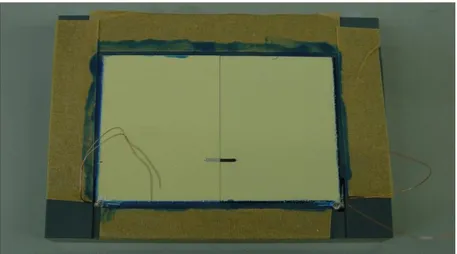
In order to properly connect both materials for the electrochemical tests, it was necessary to create a sample holder that keeps these two materials in contact during the test and avoids their separation, especially in the salt spray test where the samples are placed at an angle of 60 º with the horizontal plane.
AA2024 CFRP AA2024 CFRP 4.05 cm 5.10 cm
In order to solve this problem, the first aim was to draw the sample holder and the shape of the samples using the SolidWorks design program. In annex, the scheme of the sample holder and the measurements for the AA2024 and CFRP samples are represented. The sample holder was divided into two parts: one (Peca1_final) to apply the sample and the other to support and fix the sample to the holder (Peca2_final) using pressure, the final draw of both pieces are presented in Annex.
Figure 10 represents the final form of the holder for the samples. It consists on two
different parts made of plastic and connected with 2 screws.
Figure 10 - Sample holder used in Airbus group
To design this sample holder it was necessary to consider some critical points, for example, make the surface completely flat, avoid the crevice corrosion between the two materials (CFRP and AA2024), create a way for solution flow through the sample holder
CFRP AA2024
In order to solve some problems during the studying of corrosion processes, one point was to put both materials at the same level and to create a flat surface. For this, all the samples were cut with same height and the sample holder was made to compensate the difference of height between the aluminum (2mm) and CFRP (5mm) samples.
To fix the material into the sample holder, a chamfer was created in the both sides of each material directly in contact with the sample holder.
The way used to prevent the crevice corrosion between both materials, was to paint the sides of the materials which are directly in contact into each other. This prevented the direct contact and fast corrosion between two materials.
On the bottom of the sample holder a gap to facilitate the flow of any liquids presented in the samples was created, preventing the stagnation of solutions.
In order to connect both materials and create the galvanic couple, right next to the gap, into the sample-holder a part of the chamfer present in the sample was removed and the copper wire, which were placed using silver paint as a conductive material and super glue to fix the wires to the materials, first the area was painted with silver glue, than it was attached the wires and paint again with silver glue in order to have a good conduction and on top it was applied the super glue to fix to the holder the copper wires (Figure 11).
Some sealant was applied around the sample to prevent the solution enter to the backside of the sample.
2.5. LDH synthesis
The first step of this work is the synthesis of “smart” nanocontainers and loading these nanocontainers with inhibitors (MBT, BTA, tungstate, metavanadate, molybdate in the case of Mg/Al LDH and Ce3+ cations in the case of bentonite).
The synthesis of LDH was effectuated according to the experimental procedure previously described [1]. Briefly, the LDH was prepared by slow adding a mixture of 0.5M magnesium nitrate and 0.25M aluminum nitrate deaerated solution (V=200ml) to 1.5M sodium nitrate deaerated solution (V=400ml) under continue stirring. The pH of the solution was controlled with 2M NaOH solution and kept between 7 and 9 during the synthesis. After this step, the LDH structure was formed under 100ºC during 4 hours, and the pH of this solution was kept between 9 and 10.
After the formation of LDH, in order to separate the slurry from the solution, the mixture was centrifuged at 10 000 rpm during 90 seconds. The obtained LDH precipitation was washed with deionized water and centrifuged again, this procedure was repeated two times in order to eliminate the presence of sodium nitrate into the slurry. Deionized deaerated water was used as a solvent for LDH synthesis, in order to prevent the formation of carbonates during the process. The deaeration of the solution was performed by N2 (Figure
12). N2 NaOH Sodium Nitrate Magnesium nitrate with aluminium nitrate
Bentonite was used as a nanocontainer for Ce3+ without any further treatment or purification.
Before the loading of nanocontainers with anti-corrosion inhibitors and their application into coating formulation, the characterization of empty nanocontainers was performed with
1. Scanning electron microscopy (SEM) in order to analyze their size and form, for this analysis all the samples were immobilized with carbon glue.
2. X-ray diffraction (XRD) in order to analyze the crystalline phases of the nanocontainers.
To perform these analyses the sample were dried at 60º C during 12 hours because the LDH slurry contains about 80% of water.
2.6. Inhibitors intercalation
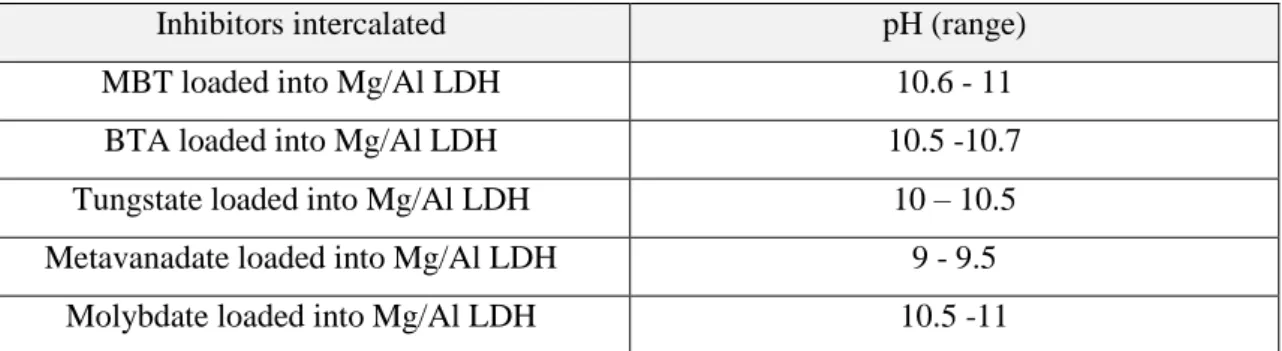
The intercalation of the inhibitors was performed by anion-exchange method. Solutions with 0.1M concentration of the inhibitors were prepared. For the formation of the ionic form of the inhibitor, the pH of the solution was adjusted for each type of inhibitor (Table 1).
Table 1 - pH used for intercalation of different inhibitors into Mg/Al LDH
Inhibitors intercalated pH (range)
MBT loaded into Mg/Al LDH 10.6 - 11
BTA loaded into Mg/Al LDH 10.5 -10.7
Tungstate loaded into Mg/Al LDH 10 – 10.5 Metavanadate loaded into Mg/Al LDH 9 - 9.5
Molybdate loaded into Mg/Al LDH 10.5 -11
To 125 ml of the formed solution, about 20 g of LDH slurry were added. The mixture was kept for 24 hours under continuous stirring. The formed slurry of LDH loaded with inhibitor was centrifuged at 10000 rpm during 90 sec and washed with deionized water three times (Figure 13). The work with MBT inhibitor was performed into the bottles covered with metallic foil in order to prevent MBT degradation from Sun light [27].
Figure 13- Inhibitors intercalation
In order to produce the bentonite nanocontainers loaded with Ce3+, firstly a solution of Ce3+ (0.56 mol/L) in deionized water was prepared (40 ml) and stirred until all the salt is completely dissolved. The obtained solution was combined with bentonite (2 g) and continuously stirred during 24 hours. After this, the solution was filtered with vacuum filtration technique and washed with deionised water. The synthesized nanocontainers with inhibitors were also characterized with SEM and XRD methods in order to confirm the successful inhibitors intercalation.
2.7. Synergistic mixtures
Synergistic mixture is a mixture of several inhibitors in which the inhibition efficiency (IE) of the mixture of inhibitors is higher than the sum of inhibition efficiencies of included components.
The values of the IE is calculated using equation 13: 𝐼𝐸 =𝐶𝑅0 - CRinh
𝐶𝑅0 (13)
where CR0 is the corrosion rate in the non-inhibited medium and CRinh is the corrosion rate in the presence of inhibitor. The synergistic parameter (S) is calculated using equation suggested [6] (equation 14):
BTA
MBT Metavanadate
where IE1+2=(IE1+IE2)−(IE1·IE2). The parameters IE1, IE2 and IE12 are calculated inhibition efficiencies for inhibitors 1, 2 and the mixture of 1 and 2, respectively. Values of S>1 indicate the synergistic behavior of selected inhibitors in combination.
In order to find the most effective inhibitive combinations some mixtures of organic and inorganic inhibitors were tested during this work of this Master thesis (Table 2). Table 2 – Synergistic mixtures produced in Aveiro University and Airbus Group.
Synergistic mixtures
MBT loaded into Mg/Al LDH mixed with Ce3+ loaded into bentonite
BTA loaded into Mg/Al LDH mixed with Ce3+ loaded into bentonite
Metavanadate loaded into Mg/Al LDH mixed with Ce3+ loaded into bentonite
Tungstate loaded into Mg/Al LDH mixed with Ce3+ loaded into bentonite
3.Results
3.1.Research laboratory
3.1.1. Nanocontainer characterization
3.1.1.1. Scanning electron microscopy (SEM)
Figure 14 shows as an example of the typical results for Mg/Al LDH (a), Zn/Al
LDH (b), Mg/Al LDH loaded with MBT (c) and Zn/Al LDH loaded with MBT (d). The typical size of LDH crystal does not depend on the inhibitors inside and it is defined by the cationic composition of the layers.
a) Mg/Al LDH b) Zn/Al LDH
c) Mg/Al LDH loaded with MBT d) Zn/Al LDH loaded with MBT
Figure 14 - SEM images for the different types of nanocontainers, used in this work
3.1.1.2. X-ray diffraction (XRD)
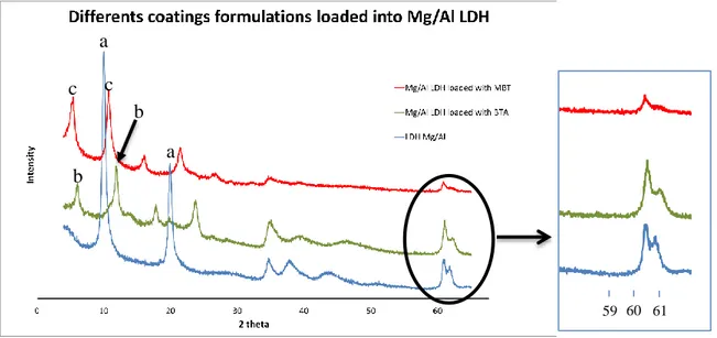
Figure 15 represents the XRD patterns of Mg-Al LDH before (a) and after
Figure 15 - XRD patterns of Mg/Al LDH before (a), and after intercalated with BTA (b) and MBT (c)
In the XRD pattern of the parental Mg-Al LDH, one can see two characteristics peaks of the LDH structure, at 2 Theta (2θ) equal to 9.83º and 19.80º, marked as “a”. These reflections correspond to a basal spacing of 8.94 Å. Taking into account the thickness of Mg/Al hydroxide layer (4.77 Å23), the space available for NO3- is 4.17 Å.
In the XRD pattern of Mg/Al LDH loaded with MBT, it is possible to observe that the main LDH reflections are shifted to the smaller 2 Theta range can be found at 5.19º and 10.58º respectively (marked “c”). These angles correspond to the basal spacing of 16.67 Å and 17.03Å respectively. Hence the gallery height available for MBT is equal to 11.63Å.
In the pattern of Mg/Al LDH loaded with BTA (“b”), the characteristic peaks are also shifted to smaller values of 2θ in comparison with those of the parental LDH structure. The two peaks, representative for this material, located at 5.75º and 11.50º, respectively, which gives the basal spacing equal to 15.5 Å and the gallery height available for BTA anions equal 10.44 Å.
The diffraction reflection at 2θ of about 61º (inset in Figure 15), does not depend on the nature of intercalated anions and corresponds to the planes perpendicular to double cations layers [28]. One can see that the anion exchanges resulted in no change in position of this reflection thereby indicating that the exchange reactions do not affect composition and structure of the double cations layer.
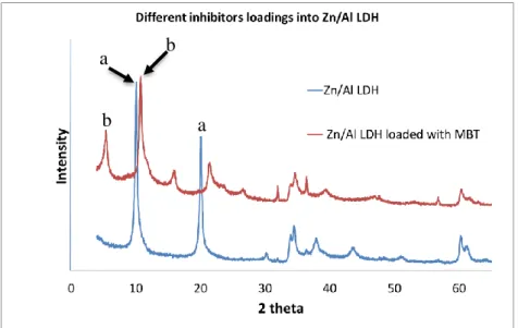
Figure 16 represents the XRD patterns of the parental Zn/Al NO3- LDH (a) in a a b c c b 59 60 61
Figure 16 – XRD of Zn/Al LDH loaded with MBT (b) as compared with XRD the parental Zn/Al LDH (a) (intercalated with the nitrate)
In the XRD pattern of the parental Zn/Al LDH, there are two peaks at 2 Theta about 9.87º and 19.90º corresponding to the basal spacing value of 8.91 Å. The thickness of Zn/Al hydroxide layer is about 4.71 Å, then gallery height available for NO3- anions equals 4.20 Å. This value is very similar to the respective value for the parental Mg/Al LDH.
In the case of Zn/Al LDH loaded with MBT, these two characteristic peaks in the XRD pattern are shifted to smaller values of 2θ and located at 5.13º and 10.53º, corresponding to the basal spacing value equal to 16.78 Ȧ. The height of the gallery space occupied by MBT- anions and water molecules is 12.07 Ȧ.
3.1.2.Results of the different types of coated formulations 3.1.2.1.Immersion test
The immersion tests of galvanically coupled CFRP and AA2024 were performed into aqueous 0.5M NaCl solution. The obtained results show that the corrosion of the samples with the different types of coating formulation starts at different times (Table 3 and
Figure 17). Figure 17 shows the sample with the minimum of resistance against corrosion
and the sample with the maximum resistance to corrosion. Table 3 shows the amount of time in hours, which is required for each type of coating formulation to present the first signs of corrosion on sample.
a b
a) Without inhibitors in the coating formulation (0, 18, 24 h)
b) BTA loaded into Mg/Al LDH mixed with cerium loaded into
bentonite ( 0, 48, 72 h)
c) MBT loaded into Mg/Al LDH mixed with cerium loaded into
bentonite (0, 48, 96 h)
Figure 17 - Corrosion tests for different types of coating
In Figure 17 it is observed that corrosion starts to appear from 18 hours (coating without any inhibitors) up to 96 hours (synergistic mixture of MBT loaded into Mg/Al LDH mixed with cerium loaded into bentonite).
In sample (a) is showed as a reference: it does not contain any additives inside the paint. The corrosion of this sample starts very fast (after 18 hours of immersion).
Samples (b) and (c) in Figure 17 represent the mixture of inhibitors loaded into “smart” nanocontainers and applied into coating formulation (about 16% of the coating formulation). Figure 17 -b represents the sample of which the coating contains BTA loaded into Mg/Al LDH mixed with Ce3+ loaded into bentonite. The corrosion of this sample appears after 72h of immersion. Figure 17-c represents the coating formulation containing MBT loaded into Mg/Al mixed with Ce3+ loaded into bentonite. In this case one observes that the corrosion starts to appear after 96 hours of immersion.
In some cases some corrosion spots are viewed on the surface of the samples very earlier. The reason for this behavior can be explained with poor application of the coating by a bar-coater (40µm of raw material) and low reproducibility of the experiments (immersion test) during laboratory tests.
0 h 18 h 24 h 0 h 0 h 48 h 48 h 72 h 96 h CFRP AA2024
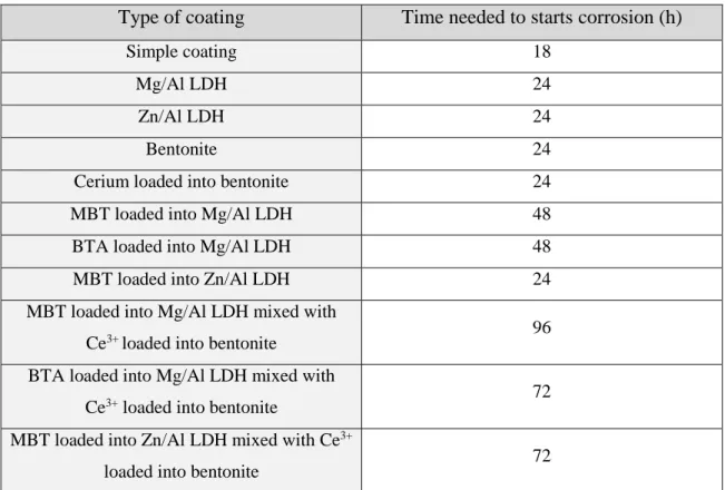
Table 3 - Time needed to corrosion initiation for samples with different coatings
Type of coating Time needed to starts corrosion (h)
Simple coating 18
Mg/Al LDH 24
Zn/Al LDH 24
Bentonite 24
Cerium loaded into bentonite 24
MBT loaded into Mg/Al LDH 48
BTA loaded into Mg/Al LDH 48
MBT loaded into Zn/Al LDH 24
MBT loaded into Mg/Al LDH mixed with
Ce3+ loaded into bentonite 96
BTA loaded into Mg/Al LDH mixed with
Ce3+ loaded into bentonite 72
MBT loaded into Zn/Al LDH mixed with Ce3+
loaded into bentonite 72
3.1.2.2.Electrochemical impedance spectroscopy (EIS)
Figure 18 represents the electrochemical impedance results for scratched and
non-scratched reference samples (no inhibitors in the coating formulation). From Figure 18 it can be seen that the decrease of resistance for the sample without scratch happens immediately between 1h and 5 hours of immersion. On the other hand, for the sample with the scratch, the values of resistance decrease between 5 hours and 10 hours of immersion.
However it should be mentioned that at the beginning of the measurement the resistance in the reference coating without any artificial scratch is lower than in the scratched sample. This could be explained by a poor quality of the paint on the non-scratch sample and a good application on scratched sample at the same time.
Figure 18 – EIS for reference sample, a) without scratch, b) scratched.
Figure 19 represents the comparison between the reference sample (with scratch)
and the sample coated with tungstate loaded into Mg/Al LDH mixed with cerium loaded into bentonite in the coating formulation (without scratch).
Figure 19 – EIS for a) Reference sample (scratched) and b) Tungstate loaded into Mg/Al LDH mixed with Ce3+ loaded into bentonite (no scratch).
The analysis of these graphics, shows that after 1 hour of immersion the reference sample with scratch has values of |Z| and theta in same order of magnitude as the sample
b) a) a) b) c) c) d) d)
without any scratch but coated with synergistic mixtures of inhibitors loaded into nanocontainers. This can mean that all the micro-scratches naturally formed between the nanocontainers and the coating could be represented with more or less comparable size with the artificial defect which was created with the needle into reference coating.
This intermediate conclusion had effect on the next measurements where all the impedances tests were realized without any artificial defect because all of them have nanocontainers with inhibitors in the coating formulation.
Figures 20 - 23 represent the impedance measurements for the samples which
contain the mixture of inhibitors into the coating formulation without any artificial defects: 1. MBT loaded into Mg/Al LDH together with Ce3+ loaded into bentonite
(Figure 20-a).
2. MBT loaded into Mg/Al LDH (Figure 20-b).
3. BTA loaded into Mg/Al LDH together with Ce3+ loaded into bentonite (Figure 21-a).
4. Cerium loaded into bentonite (Figure 21-b).
5. Metavanadate loaded into Mg/Al LDH together with Ce3+ loaded into bentonite (Figure 22-a).
6. Metavanadate loaded into Mg/Al LDH (Figure 22-b).
7. Tungstate loaded into Mg/Al LDH together with Ce3+ loaded into bentonite (Figure 23-a).
Figure 20 – EIS analyses for a) MBT loaded into Mg/Al mixed with cerium loaded into bentonite, b) MBT loaded into Mg/Al LDH.
Figure 21 - EIS analyses for a) BTA loaded into Mg/Al mixed with cerium loaded into bentonite, b) cerium loaded into bentonite.
a) a) b) b) c) c) d) d)
Figure 22 - EIS analyses for a) Metavanadate loaded into Mg/Al mixed with cerium loaded into bentonite, b) metavanadate loaded into Mg/Al LDH.
Figure 23 - EIS analyses for a) Tungstate loaded into Mg/Al mixed with cerium loaded into bentonite, b) tungstate loaded into Mg/Al LDH.
Based on the previous figures (20 to 23), the synergistic mixture of MBT loaded into Mg/Al LDH together with Ce3+ loaded into bentonite shows a constant decrease of resistance during 48 hours in comparison with the single inhibitor MBT loaded into Mg/Al
a) b) a) b) c) c) d) d)
of immersion (resistance decrease about one order of magnitude). Comparison of all figures showed that the MBT loaded nanocontainers mixed with Ce3+ loaded nanocontainers and standalone MBT loaded into Mg/Al LDH implement a higher resistance of the sample to the corrosion environment.
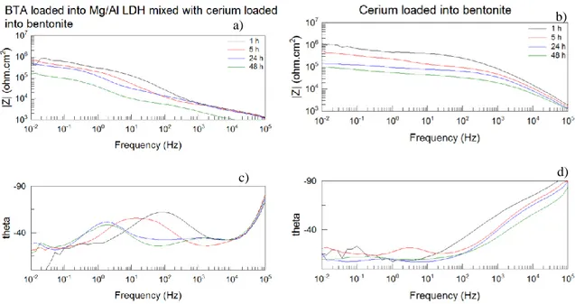
Figure 21-b represents the standalone Ce3+ inhibitor loaded into bentonite. These results show a slow and a gradual decrease of resistance during 48 hours (one order of magnitude in the summing during 48 hours).
The obtained values for the BTA loaded into Mg/Al LDH show a slowly decrease during the first 24 hours, however after this period the resistance suffer a drop.
The interesting result appears with metavanadate loaded into Mg/Al LDH nanocontainers. The resistance of the coating remains very stable during 24 hours, however between 24 hours and 48 hours the resistance significantly decreases.
The sample with the higher resistance against corrosion during the 48 hours is the one with the coating formulation containing metavanadate loaded into Mg/Al mixed with cerium loaded into bentonite the result. It shows a good resistance to corrosion during the first 24 hours of immersion, but between 24 - 48 hours the resistance significantly decreases accomplishing the values of resistance equal for the other coatings formulations. This result matches the results obtained in Airbus Group Innovations, where, during the immersion test, the coating with metavanadate mixed with cerium inhibitors showed a really shiny surface for up to 24 hours of immersion. However after 48 hours the sample started to corrode. The ZRA measurements for this sample also show a decrease of corrosion during first-hours of experiment (see chapter 3.2.2.1).
Figure 23-a represents the EIS measurements for the coating formulation
containing tungstate loaded into Mg/Al mixed with cerium loaded into bentonite. The initial resistance (106 Ω.cm2) is lower than the resistance in the standalone inhibitor (107 Ω.cm2), of tungstate loaded into Mg/Al LDH. However after 48 hours of immersion both samples show the same order of magnitude for resistivity against corrosion.
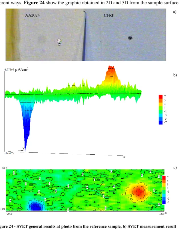
3.1.2.3. Scanning vibrating electrode technique (SVET)
For a general acknowledgement the SVET results usually can be presented in two different ways, Figure 24 show the graphic obtained in 2D and 3D from the sample surface.
Figure 24 - SVET general results a) photo from the reference sample, b) SVET measurement result in 3D, c) SVET measurement result in 2D
The results demonstrated in Figure 24 show 2 peaks which are located in places of
a)
b)
c)
AA2024 CFRP
left peak). This peaks represent the corrosion currents from the sample. The objective of the application of SVET technique is to quantify the corrosion currents and to analyze their decreases through the time in the presence of inhibitors.
Table 4 and Table 5 represent the SVET analyses for the model reference sample
(1), for a single inhibitor MBT loaded into Mg/Al LDH (2) and tungstate loaded into Mg/Al LDH (3) both added into coating formulation and for two different examples of inhibitive mixture (MBT loaded into Mg/Al LDH mixed with Ce3+ loaded into bentonite(4) and tungstate loaded into Mg/Al LDH mixed with Ce3+ loaded into bentonite (5)) at the beginning, after 10 and 24 hours of immersion. Tables 4 and 5 represent the coating loaded with inhibitors which showed the best results during previous tests such as Salt spray test, immersion test, Zero resistance ammeter (ZRA) and EIS made in Airbus Group.
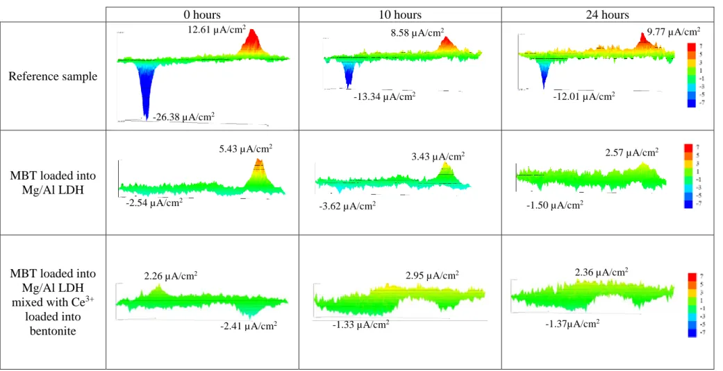
Table 4 – SVET map’s for different types of coating formulation using MBT as inhibitor after 0h, 10h and 24h of immersion.
0 hours 10 hours 24 hours
Reference sample MBT loaded into Mg/Al LDH MBT loaded into Mg/Al LDH mixed with Ce3+ loaded into bentonite -1.37µA/cm 2 -1.33 µA/cm2 -2.41 µA/cm2 -26.38 µA/cm2 12.61 µA/cm2 8.58 µA/cm2 -13.34 µA/cm2 9.77 µA/cm2 -12.01 µA/cm2 -2.54 µA/cm2 5.43 µA/cm2 -3.62 µA/cm2 -1.50 µA/cm2 3.43 µA/cm2 2.57 µA/cm2
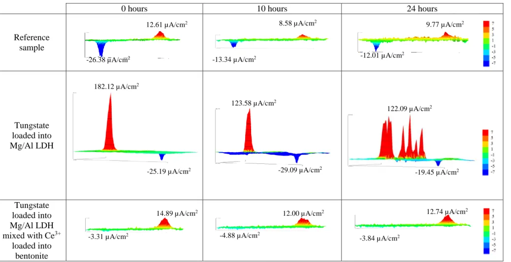
Table 5 - SVET map’s for different types of coating formulation using tungstate as inhibitor after 0h, 10h and 24h of immersion.
0 hours 10 hours 24 hours
Reference sample Tungstate loaded into Mg/Al LDH Tungstate loaded into Mg/Al LDH mixed with Ce3+ loaded into bentonite -3.84 µA/cm2 -4.88 µA/cm2 -3.31 µA/cm2 12.61 µA/cm2 -26.38 µA/cm2 8.58 µA/cm2 -13.34 µA/cm2 9.77 µA/cm2 -12.01 µA/cm2 182.12 µA/cm2 -25.19 µA/cm2 123.58 µA/cm2 -29.09 µA/cm2 122.09 µA/cm2 -19.45 µA/cm2
These results show a predictable output, where the standalone inhibitors have higher values of current in comparison with the synergistic mixture values. For the reference sample the current can be either higher in comparison with loaded coating formulation (as in the case the standalone MBT loaded into Mg/Al LDH) or lower (as in the case of standalone tungstate loaded into Mg/Al LDH).
Table 6 presents the average of the maximum and minimum peak values for all the
inhibitors and their mixtures analyzed with SVET during this work (last 5 hours of measurement are counted). The maximum correspond to the AA2024 sample corrosion peak and the CFRP sample cathodic reaction correspond to the negative peak value.
Table 6 – Maximum and minimum average of the corrosion peaks and average total currents.
Type of coating formulation (single inhibitors) Average value (µA/cm2) Total current value (A.10 -8) Type of coating formulation (reference sample / synergistic mixtures) Average value (µA/cm2) Total current value (A.10-8)
Reference sample Max: 8.24 Min: -10.84 Max: 11.38 Min: -5.52 Ce3+ loaded into Bentonite Max: 58.82 Min: -25.36 Max: 9.33 Min: -11.71 MBT loaded into Mg/Al LDH Max: 2.38 Min: -2.23 Max: 0.91 Min: -0.87 MBT loaded into Mg/Al LDH mixed with Ce3+ loaded into bentonite Max: 2.63 Min: -1.69 Max: 0.72 Min: -6.76
BTA loaded into Mg/Al LDH
Max: 28.80 Min: -29.73
BTA loaded into Mg/Al LDH mixed with Ce3+ loaded into bentonite Max: 6.67 Min: -4.22 Max: 2.43 Min: -2.51 Metavanadate loaded into Mg/Al LDH Max:18.30 Min:-3.39 Max:9.68 Min:-9.21 Metavanadate loaded into Mg/Al LDH mixed with Ce3+ loaded into bentonite
Max: 19.32 Min: -3.62
Max: 7.54 Min: -4.39
Tungstate loaded into Mg/Al LDH Max:140.02 Min: -22.34 Max: 27.15 Min: -22.88 Tungstate loaded into Mg/Al LDH mixed with Ce3+ loaded into bentonite
Max: 13.17 Min: -4.27 Max: 9.86 Min: -6.37 Molybdate loaded into Mg/Al LDH mixed with Ce3+ Max: 12.63 Min: -6.26 Max: 2.37 Min: -4.93
From Table 6, it is evident that the average values of the corrosion currents decrease for the mixture of inhibitors in comparison with standalone inhibitors. One exception is the metavanadate inhibitor loaded into Mg/Al LDH. However even in this case the values remain very similar to the metavanadate synergistic mixture.
The average values of corrosion current show a higher inhibitive effect in the case of two combined inhibitors in the same coating formulation. The highest effect is observed for the mixture of MBT loaded into Mg/Al LDH together with Ce3+ loaded into bentonite.
In the case of molybdate loaded into Mg/Al LDH mixed with cerium loaded into bentonite, the result shows a low average corrosion current. However from the comparison of all entire results, it’s possible to conclude that the molybdate was release from the coating not only in the place of artificial defects but also in a large amount from all the coating (Figure 25) making the solution rich in molybdate.
This solution creates the inhibitive protection effect in the case of stationary conditions and becomes not effective in the case of flow solution.
Figure 25 - SVET measurement from coating formulation molybdate loaded into Mg/Al LDH mixed with cerium loaded into bentonite (2 hours of immersion)
Figure 26 represents the variation of corrosion currents during 24 hours for the
reference sample, for four different types of coating formulation (standalone MBT loaded into Mg/Al LDH, cerium loaded into bentonite, the synergistic mixture MBT loaded into Mg/Al LDH together with cerium loaded into bentonite and the reference coating without any inhibitors).