Design of a high-speed transmission
for an electric vehicle
Carlos Daniel Pires Rodrigues
Dissertation submitted to
Faculdade de Engenharia da Universidade do Porto for the degree of:
Mestre em Engenharia Mecânica
Advisor:
Prof. Jorge Humberto Oliveira Seabra Co-Advisor:
Prof. José António dos Santos Almacinha
Unidade de Tribologia, Vibrações e Manutenção Industrial Departamento de Engenharia Mecânica
Faculdade de Engenharia da Universidade do Porto
The work presented in this dissertation was performed at the Tribology, Vibrations and Industrial Management Unit Department of Mechanical Engineering
Faculty of Engineering University of Porto Porto, Portugal.
Carlos Daniel Pires Rodrigues
E-mail: [email protected], [email protected]
Faculdade de Engenharia da Universidade do Porto Departamento de Engenharia Mecânica
Unidade de Tribologia, Vibrações e Manutenção Industrial Rua Dr. Roberto Frias s/n, Sala M206
4200-465 Porto Portugal
Abstract
For decades, the hegemony of internal combustion vehicles has led to an improvement, by the automotive industry, of transmissions, in order to increase the torque and reduce the rotational speed from the engine.
These transmissions are quite complex, having up to 7 speeds, with the aim of retrieving the highest possible efficiency from the considerably inefficient internal combustion engines. Nowadays, environmental concerns and strong governmental regulations, as well as, buying incentives, have presented electric vehicles as a viable solution to consumers while being in line with the new global paradigm of sustainability.
Electric vehicles turn to electric motors to transform electric energy in mechanical energy. Since these motors are widely used in other industrial applications, they are already a mature technology. They have an ideal torque and power curves regarding vehicle operation. Due to these favourable characteristics, the transmission of an electric vehicle is simpler, presenting itself as a conventional reducer with respect to the overall geometry, having usually only one speed ratio between the input and the output.
However, the high rotational speed associated with compact electric motors, makes it necessary to take some factors into account when designing a transmission: gear design, lubrication method selection, as well as rolling bearing selection are just some of the concerns that will be further elaborated in this thesis, in order to reduce power losses, ensuring a good efficiency and, at the same time, control the noise generated.
The mechanical differential, which is present in all internal combustion vehicles, is a system that provides the vehicle with the capacity to change direction steadily, however it cannot be continually controlled. Thus, the idea of using an electronic differential seems interesting, since it would reduce the number of mechanical components and, through the ever-increasing network of sensors and data acquired by the vehicles themselves, it is possible to independently control the rotational speed of each front wheel continuously, leading to greater safety and comfort when the vehicle is changing direction.
Keywords: electric vehicles, transmission, gears, electronic differential, splash lubrication.
Resumo
Durante largas décadas, a hegemonia dos veículos de combustão interna levou a um aperfeiçoamento por parte da indústria automóvel das transmissões para aumentar o binário e reduzir a velocidade provenientes do motor.
Estas transmissões são bastante complexas, podendo ter até 7 velocidades, de forma a extrair o mais rendimento possível dos pouco eficientes motores de combustão interna.
Atualmente, preocupações ambienteais e fortes regulações governementais, bem como, elevados incentivos de compra, tornaram os veículos elétricos como uma solução viável para os consumidores e que vai de encontro ao novo paradigma mundial de sustentabilidade.
Os veículos elétricos recorrem a motores elétricos para transformar a energia elétrica em energia mecânica. Uma vez que estes motores são amplamente utilizados em outras aplicações industriais, já se apresentam como uma tecnologia madura. Eles possuem uma curva de binário e de potència ideal para os automóveis. Devido a estas características favoráveis, a transmissão de um veículo elétrico é mais simples, apresentando-se como um redutor convencional em termos geométricos, tendo apenas uma razão de velocidades entre a entrada e a saída. Porém, a elevada velocidade de rotação associada aos motores elétricos compactos, leva a que sejam necessários cuidados na concepção da transmissão: desenvolvimento das engrenagens, escolha do método de lubrificação ideal e escolha dos rolamentos são apenas algumas das questões que serão aprofundadas nesta dissertação, de forma a que as perdas de potência sejam reduzidas, garantindo uma boa efficiência e, ao mesmo tempo, controlar o ruído gerado.
O diferencial mecânico, presente em todos os veículos de combustão interna, é um sistema que proporciona a capacidade para um veículo curvar de forma correta, mas que não é possível regular enquanto veículo está em movimento. Assim, surgiu a ideia de usar um diferencial eletrónico, reduzindo o número de componentes mecânicos e, através da cada vez mais elevada rede de sensores e informação adquirida pelos próprios veículos, seja possível realizar um controlo independente e continuado das velocidades de rotação das duas rodas da frente, levando a uma maior segurança e conforto quando o veículo está a mudar de direção.
‘Nós somos o que fazemos. O que não se faz não existe.’
Acknowledgements
I would like to thank my thesis advisor Prof. Jorge Seabra and co-advisor Prof. José Almacinha of the Faculty of Engineering at University of Porto. They consistently allowed this thesis to be my own work and steered me in the right direction providing guidance and support, as well as recommendations and several revisions throughout the semester.
I would also like to thank all my friends which provide a very pleasant environment to evade, for short periods of time, the work atmosphere.
Finally, I give my warmest thanks to my family, in particular to my parents, for the continuous encouragement and everything that they have provided me along the years, and whose support after all is the most essential.
Contents
Abstract i Resumo ii Acknowledgements vii 1 Introduction 1 1.1 Introduction. . . 1 1.2 Objectives . . . 1 1.3 Layout . . . 2 2 Background Theory 5 2.1 Electric vehicles. . . 5 2.2 Electrification . . . 8 2.3 Automotive industry . . . 10 2.4 Energy storage . . . 11 2.4.1 Battery . . . 12 2.4.2 Fuel cell . . . 13 2.4.3 Ultra-capacitor . . . 13 2.5 Powertrain . . . 13 2.5.1 Electric motor . . . 15 2.5.2 Transmission . . . 18 2.5.3 Differential . . . 21 2.5.4 Projects . . . 22 3 Project characteristics 27 3.1 Vehicle specifications . . . 27 3.2 Electric motor. . . 28 3.3 Vehicle performance . . . 293.3.1 Maximum speed and gradeability . . . 29
3.3.2 Acceleration performance . . . 30
3.3.3 Preliminary results . . . 32
3.4 Transmission . . . 32
3.4.1 Number of stages and overall transmission ratio. . . 33
3.4.2 Geometry . . . 33
4 Gear design 37 4.1 Application factor . . . 37
4.2 Road profile . . . 38
CONTENTS
4.4 Material . . . 39
4.5 Manufacturing Quality . . . 40
4.6 Tooth flank surface roughness . . . 40
4.7 Module . . . 41 4.8 Helix angle . . . 41 4.9 Face width . . . 41 4.10 Profile shift . . . 42 4.11 Contact ratio . . . 42 4.12 Comparison . . . 43 4.13 Final results. . . 45
5 Shaft design and bearing selection 49 5.1 Shaft layout . . . 49
5.1.1 Material . . . 50
5.1.2 Relative position and direction of rotation . . . 50
5.1.3 Shaft ends . . . 52
5.1.4 Splines . . . 53
5.1.5 Key connections . . . 54
5.2 Rolling bearings . . . 55
5.2.1 Rolling bearings selection criteria . . . 55
5.2.2 Arrangement . . . 56
5.3 Rolling bearings selected . . . 56
5.4 Shaft analysis . . . 60
5.4.1 Final shafts . . . 60
5.4.2 Applied stresses (static and fatigue) . . . 64
5.4.3 Deflection . . . 64
5.4.4 Critical speed . . . 66
6 Gear modification sizing 67 6.1 Theoretical flank modifications . . . 67
6.2 Crowning to compensate tolerances. . . 68
6.3 Profile modifications . . . 70
7 Lubrication and Sealing 75 7.1 Lubricant selection . . . 76 7.2 Lubrication method . . . 77 7.3 Sealing. . . 80 8 Thermal analysis 83 8.1 Power losses . . . 83 8.2 Heat dissipation . . . 87
9 Housing and Parts 93 9.1 Housing . . . 93 9.1.1 Material . . . 93 9.1.2 Design . . . 94 9.2 Parts. . . 96 9.2.1 Flanges . . . 96 9.2.2 Screws . . . 96 9.2.3 Set pins . . . 98 x
CONTENTS
9.2.4 Shaft spacer sleeves . . . 99
9.2.5 Retaining rings (circlips). . . 99
9.2.6 Plugs . . . 99
9.2.7 Parts list . . . 100
10 Assembly 101 11 Electronic differential 107 11.1 Critical cornering speed . . . 107
11.2 Ackerman steering . . . 109
12 Conclusions and future work 115 12.1 Conclusions . . . 115
12.2 Future Work . . . 117
References 118
Appendix A Steel 18CrNiMo7-6 127
Appendix B Lubricant - Castrol ATF Dex II Multivehicle 131
Appendix C Cylindrical gear pairs KISSsoft report 133
Appendix D Shaft calculation KISSsoft report 175
Appendix E Deep groove rolling bearings 301
List of Figures
2.1 Historical fleet CO2 emissions performance and current standards for
passenger cars (gCO2/km normalized to NEDC) . . . 6
2.2 Evolution of the global electric car stock 2010 – 2016 . . . 6
2.3 Typical performance characteristics of gasoline engine (left) and electric motor (right) . . . 8
2.4 Average footprint over average mass per vehicle segment in the EU 2010 Note: The error bars around the averages represent the standard deviation 8 2.5 Examples of sales prices in German market, e thousands (not including external incentives) . . . 10
2.6 Plot of a few electrochemical energy storage devices used in the propulsion application . . . 12
2.7 Six types of EV configurations . . . 14
2.8 Typical torque speed curve of an electric traction motor . . . 15
2.9 Schematics of four types of motors: Brushed DC motor (a), Permanent Magnet Synchronous Motors (b), Switched Reluctance Motor (c), Induction Motor (d). Adapted . . . 16
2.10 Exemplary efficiency maps of different electric motors with constant power 19 2.11 Single speed transmission in a PEV powertrain. S1, S2 – shafts . . . 19
2.12 Two speed dual clutch transmission in PEV powertrain. S1, S2, S3 – shafts. C1, C2 – clutches . . . 20
2.13 Twinspeed transmission with two planetary gear sets . . . 20
2.14 Continuously variable transmission with servo-electromechanical actuation system . . . 21
2.15 Typical front-wheel drive powertrain components: in an ICE vehicle (left) and in a PEV vehicle (right). . . 22
2.16 Rear-wheel drive powertrain components (left) and BMW rear differential (right) . . . 22
2.17 GETRAG 1eDT330 electrical transmission with independent transmission components and electric motors. . . 23
2.18 GKN electric axle - ’eTwinsterX’. . . 23
2.19 ESKAM axle module with integrated motors (left). Gearbox (right). . . 24
2.20 Schematic design of the drive train (left) and gear set (right). . . 24
2.21 Dual motor transmission from Visio.M project (left) and transmission diagram (right).. . . 25
3.1 Torque-power peak curve of the Zytek 25 kW electric motor . . . 28
3.2 Forces acting on a vehicle moving uphill . . . 30
LIST OF FIGURES
3.4 Two-stage parallel transmission arrangement with the input and output at
opposites shaft ends . . . 34
3.5 Two independent transmission arrangements in the same housing . . . 34
3.6 Direction of forces acting on a helical gear mesh. . . 35
4.1 Axial pitch (px) of helical gears . . . 42
5.1 DIN 509 - Type E undercut . . . 50
5.2 Initial shaft relative position. . . 51
5.3 Final shaft relative position . . . 51
5.4 Direction of shaft rotation . . . 52
5.5 Final shaft arrangement and respective shaft rotational directions. . . 52
5.6 Vehicle forward direction with associated tire rotation and transmission architecture . . . 53
5.7 Locating/non-locating bearing arrangement . . . 56
5.8 Shaft A final design layout. . . 60
5.9 Torque diagram of shaft A . . . 60
5.10 Force diagram of shaft A. . . 61
5.11 Shaft B final design layout . . . 61
5.12 Torque diagram of shaft B . . . 62
5.13 Force diagram of shaft B. . . 62
5.14 Shaft C final design layout. . . 63
5.15 Torque diagram of shaft C . . . 63
5.16 Force diagram of shaft C. . . 63
6.1 Crowning (left) and helix angle modification (right) . . . 68
6.2 Load distribution over face width, before and after modifications . . . 68
6.3 Load distribution over face width considering manufacturing allowances with previous modifications (left) and proposed (right) . . . 69
6.4 Load distribution over face width considering manufacturing allowances with the final modifications . . . 70
6.5 Arc-like profile modification . . . 71
6.6 Peak-to-peak transmission error. . . 72
6.7 Efficiency . . . 72
6.8 Peak-to-peak transmission error, radar chart with 100 % load (red) and 80 % load (blue) . . . 73
6.9 Efficiency, radar chart with 100 % load (red) and 80 % load (blue) . . . 73
7.1 Relation between coefficient of friction and sliding speed (Stribeck curve) . 75 7.2 Typical friction zones on tooth flanks at high contact pressures . . . 76
7.3 Flanges position relative to the gear . . . 78
7.4 Influence of axial and radial clearances on churning losses . . . 78
7.5 Housing layout with flange and deflectors . . . 79
7.6 Transmission arrangement with the defined oil level. . . 79
7.7 Pumping effect by the SKF Wave seal . . . 80
8.1 Composition of transmission power loss . . . 83
8.2 Partially submerged gear in oil bath . . . 84
8.3 Splash lubrication method with two oil levels . . . 88
8.4 Housing with thermal finning . . . 89 xiv
LIST OF FIGURES
9.1 Types of housings. . . 94
9.2 Housing interior. . . 94
9.3 Housing exterior . . . 95
9.4 Housing exterior, detailed view of connection structure . . . 95
9.5 Housing interior (other view) . . . 95
9.6 Cover interior . . . 96
9.7 Cover exterior. . . 96
9.8 Cover exterior, detailed view of fins. . . 97
9.9 Interior flange . . . 97
9.10 Exterior flange . . . 97
9.11 Detail of flange sheet corrugation . . . 98
9.12 Spring-Type Straight Pin . . . 98
9.13 Conical thread plugs . . . 100
11.1 Free-body diagram of a vehicle turning left . . . 108
11.2 Ackerman model of cornering trajectory . . . 110
11.3 Rotational speed of wheel and motor over a vehicle speed range (R = 9 m) 112 11.4 Rotational speed of wheel and motor over a vehicle speed range (R = 30 m)112 11.5 Influence of K gradient in steering . . . 113
List of Tables
2.1 Specifications for two ICE vehicles and the EV counterpart . . . 9
2.2 Properties of several energy storage types . . . 12
2.3 Categories of EV powertrain structures. . . 14
2.4 Evaluation of four electric machine types. . . 18
3.1 Technical data for the Zytek Automotive 25 kW electric motor . . . 28
3.2 Vehicle properties, coefficients and other factors. . . 29
3.3 Relevant calculations for three specified points (see figure 3.3) . . . 32
3.4 Relevant calculations for acceleration . . . 32
4.1 Application factor (Ka) . . . 37
4.2 Single motor input for an urban road profile . . . 38
4.3 Road profile . . . 38
4.4 Gear surface roughness. . . 40
4.5 Cylindrical gear pair for the first stage (Designs A – F) . . . 43
4.6 Cylindrical gear pair for the second stage (Designs G – I) . . . 44
4.7 General transmission results . . . 45
4.8 Summary of the first stage cylindrical gear pair specifications . . . 46
4.9 Summary of the first stage cylindrical gear pair specifications according to maximum torque and maximum speed . . . 46
4.10 Summary of the second stage cylindrical gear pair specifications. . . 47
4.11 Summary of the second stage cylindrical gear pair specifications according to maximum torque and maximum speed. . . 47
5.1 Summary of selected bearings for shaft A and operating parameters for maximum torque . . . 57
5.2 Summary of selected bearings for shaft B and operating parameters for maximum torque . . . 58
5.3 Summary of selected bearings for shaft C and operating parameters for maximum torque . . . 59
5.4 Gear forces and moments . . . 64
5.5 Summary of the static and fatigue analysis . . . 64
5.6 Stressed zones in the shafts . . . 65
5.7 Deflection analysis for the transmission shafts . . . 65
5.8 Deflection analysis at meshing zones . . . 66
5.9 Shaft critical speeds . . . 66
6.1 Proposed tooth trace modifications . . . 67
6.2 Face load factor KHβ . . . 68
LIST OF TABLES
6.4 Initial proposed values for tip relief . . . 71
6.5 Tip relief minimum and maximum values for step analysis . . . 71
6.6 Summary of concluding values for the considered solutions . . . 73
7.1 Parameters necessary for the calculation of Γ . . . 79
7.2 Calculations results for Γ parameter . . . 80
7.3 Operating temperature of seal materials . . . 81
7.4 Input shaft radial seal characteristics . . . 82
7.5 Output shaft radial seal characteristics . . . 82
8.1 General calculation parameters . . . 85
8.2 Calculations parameters that change with load . . . 86
8.3 Summary of calculation results for churning torque . . . 86
8.4 Churning losses for the right wheel transmission. . . 87
8.5 Transmission power losses for the right wheel transmission . . . 87
8.6 Parameters to perform thermal calculations . . . 91
8.7 Variables which depend on load . . . 91
8.8 Heat dissipation results . . . 91
9.1 Transmission parts list . . . 100
10.1 Transmission assembly steps. . . 101
11.1 Calculation parameters and results . . . 109
11.2 Summary of the required parameters . . . 111
11.3 Summary of the results for the critical cornering speed (R = 9 m; v=vc = 29,8 km/h). . . 111
11.4 Summary of the results for understeer and oversteer conditions . . . 113
Acronyms
AC Alternating Current BEV Battery Electric Vehicle BLDC Brushless DC
BMS Battery Management System BRS Boost Recuperation System
CVT Continuously Variable Transmission DC Direct Current
EM Electric Motor
EREV Extended Range Electric Vehicle ESKAM Electrically Scalable Axial-Module EV Electric Vehicle
FPM Fluorocarbon rubber
FVA Forschungsvereinigung Antriebstechnik, the Research Association for Drive Technology
GHG Greenhouse Gas
HEV Hybrid Electric Vehicle
iBAS Integrated Belt Alternator Starter ICE Internal Combustion Engine IM Induction Motor
LSD Limited Slip Differential NBR Acrylonitrile-butadiene rubber NEDC New European Driving Cycle NVH Noise, Vibration and Harshness OEM Original Equipment Manufacturer PEV Pure Electric Vehicle
PHEV Plug-In Hybrid Electric Vehicle
PMSM Permanent Magnet Synchronous Motor PPTE Peak-to-Peak Transmission Error SRM Switched Reluctance Motor TUM Technical University of Munich WRSM Wound Rotor Synchronous Motor
Nomenclature
Symbol Description Unit
a Center distance mm
Aair Ventilated housing area m2
ad Reference center distance mm
Aca External housing area m2
Afin Total fin area m2
Aoil Internal housing area m2
Apro Projected fin area m2
Af Frontal area m2
b Face width mm
Cch Churning losses W
Cd Aerodynamic drag coefficient
-Cm Churning losses parameter
-Crr Rolling resistance coefficient
-Cα Tip relief µm
Cαf Front tire cornering stiffness µm
Cαr Rear tire cornering stiffness µm
Cβ Crowning µm
CHβ Helix angle modification µm
d Shaft diameter, distance between left and right wheel mm
da Gear tip diameter mm
dw Gear operating pitch diameter mm
Dhub Hub diameter mm
Dp Pitch diameter mm
fma Manufacturing allowance (axis misalignment)
-fHβ Manufacturing allowance (gear lead variation)
-fs Horizontal static friction
-Fa Aerodynamic drag, Axial force N
Fg Grading force N Fr Radial force N Frr Rolling resistance N Ft Tractive force N Fx Shearing force X N Fz Shearing force Z N FC Centrifugal force N Fr Froude number -g Gravitational acceleration (= 9,81) m2s−1 Gr Grashoff number
-Nomenclature
h Submerged height, height of vehicle center of mass mm
hca Overall transmission height mm
Hf Flange height mm
Ht Gear tooth height mm
i1 First stage transmission ratio
-i2 Second stage transmission ratio
-ig Overall transmission ratio
-Ja Axial distance between flange and gear mm
k Heat transfer coefficient W m−2K−1
K Ackerman steering gradient
-Ka Application factor
-KAF Root strength application factor
-KAH Flank strength application factor
-KHβ Face load factor
-lfin Depth of one fin mm
lx Flow length (path of flow filament along the housing wall) mm
L Length between front and rear axle m
LCa Roll length of the tip relief µm
LCa* Length factor
-m Mass kg
mn Normal module mm
Mx Bending moment X Nm
Mz Bending moment Z Nm
N, n Rotational speed rpm
P Distance between left and right front wheel kingpins m
Pm Electric motor power kW
¯
Pres Average resistance power kW
PVD Seal power loss W
PVL Rolling bearing power loss W
PVZP Gear power loss W
PVZ0 Churning loss W
PV Total power loss W
px Axial pitch mm
Qca Housing heat dissipation W
rt Tire radius m
R Turning radius m
R1 Turning radius of left-front wheel m
R2 Turning radius of right-front wheel m
Rp Gear pitch radius mm
Ra Average roughness µm
Rz Mean peak-to-valley roughness µm
Re Reynolds number
-Rm Tensile strength N mm−2
SF Tooth root safety
-SH Tooth flank safety
-Sm Gear submerged surface m2
Smd Wet surface of the gear flank m2
Smf Wet surface of the gear teeth m2
ta Acceleration time s
Tair Air temperature K
Tm Torque (electric motor) Nm
Toil Oil temperature K
Twall Housing wall temperature K
T∞ Ambient temperature K
Ta Taylor number
-v Velocity, Circumferential speed, Cornering speed m s−1
varg Air Velocity m s−1
vga Sliding velocity at tip m s−1
V0 Oil volume m3
xi Gear profile shift
-Wf Front vehicle load N
Wr Rear vehicle load N
Z Gear number of teeth
-Greek
symbol Description Unit
α Road grade rad
αca Air-side heat transfer coefficient W m−2K−1
αcon Convection heat transfer coefficient W m−2K−1
αn Pressure angle ◦
αoil Oil-side heat transfer coefficient W m−2K−1
αrad Radiation heat transfer coefficient W m−2K−1
β Helix angle ◦
Γ Flange parameter
-δ Rotating inertia factor, Ackerman angle
-δfin Fin thickness mm
ε Housing emission ratio
-εα Transverse contact ratio
-εβ Overlap ratio
-εγ Total contact ratio
-ζa Specific sliding at the tip
-η Efficiency
-λfin Fin thermal conductivity W m−1K−1
µs Static friction coefficient
-ν Oil kinematic viscosity [mm2/s]
νair Air kinematic viscosity [mm2/s]
ρ Density kg m−3
Chapter 1
Introduction
1.1
Introduction
The increasing necessity to preserve natural resources and environmental issues stimulate interest in the development of electric vehicles. These vehicles offer various advantages compared to internal combustion vehicles. They are more efficient, less noisy and simpler, providing a smooth drive experience.
While most of the existing vehicles work under some form of internal combustion engines, electric vehicles invoke the excellent performance specifications of an electric motor, such as high torque at low rotations and constant power during a large speed range.
High-speed electric motors are a valuable option to drive an electric vehicle. They are low weight and low cost while highly efficient. For an urban vehicle, they can deliver the necessary power to comply with the performance requirements. The major challenge is to integrate a high-speed motor and a gearbox, reducing significantly the speed and increase the torque.
Whereas, conventionally, multi-speed transmissions are employed, in electric vehicles single-speed transmissions with a fixed ratio are the standard, due to the characteristics of the electric motors.
The electric automotive industry is still in its early days, so, a great number of investigative research is required and already being performed to review specific areas so that consensus among the manufacturers and designers can be built.
1.2
Objectives
The main objective of the thesis is to design a high-speed gear transmission for a front-wheel drive urban passenger vehicle with a city drive cycle.
In a high-speed transmission, special attention has to be given to gear teeth geometry and rolling bearing selection to maximize the energetic efficiency, while, at the same time, control the noise generated, major factor in electric vehicles, since there is no noise from the internal combustion engine to suppress the transmission noise.
A further challenge is to design a simple transmission using standard manufacturing techniques, so that the manufacturing costs are reduced. To avoid the use of a mechanical differential, resulting in a minimization of the transmission weight and an increase in reliability, two electric motors associated with two independent transmissions are used. This requires an electronic differential, which acquires information from several vehicle sensors, for example, regarding wheel speed and weight distribution. The differential
1. Introduction
kinematics are obtained through the variation of the speed output from the electric motors to the transmissions input.
Lubrication and thermal efficiency require close attention, in order to assess the best lubrication method and to estimate if the transmission is operating at a proper temperature spectrum.
Mechanical design regarding assembling and manufacturing drawings will also be considered and the necessary ones presented.
1.3
Layout
The document layout follows a chapter structure, the references are presented after the last chapter and the document has the required appendices at the end. The chapters layout is:
Chapter 2
In the chapter 2 a background research regarding the current situation of the electric vehicle market is presented. Electrification, automotive industry, energy storage and powertrain solutions as well as present projects are thoroughly discussed.
Chapter 3
In chapter 3 the general design characteristics are evaluated. The required vehicle specifications and vehicle performance are reviewed. An assessment is made regarding the overall kinematic chain (number of stages and geometry) of the transmission.
Chapter 4
Both cylindrical gear pairs are designed in chapter 4. Several factors have to be derived and estimated to comply with the necessary requisites, for instance, face width, normal module and helix angle. A comparison of different gear pairs for the respective stages is going to be made to select a final solution.
Chapter 5
In chapter 5, the required shafts are designed according to standard shaft layout. Special attention is given to the relative position of the shafts with respect to each other, since it affects the load distribution that the rolling bearings have to withstand. According to the resulting loads, the bearing selection and arrangement is going to be analysed. Finally, a shaft analysis regarding stress, deflection and critical speed is performed.
Chapter 6
Chapter 6 provides an examination of the gear modification sizing. Considerations about shaft deflection, manufacturing tolerances and noise behaviour are specified and the appropriate tooth trace and profile modifications are going to be evaluated, and, if there is a positive outcome, implemented.
Chapter 7
Chapter 7 deals with lubrication and sealing. The most suitable lubrication method is selected and solutions will be assessed for the previously chosen lubrication method. Afterwards, the lubricant is selected just as the necessary sealing system with the respective shaft seals.
1.3. Layout Chapter 8
In chapter 8 a thermal analysis is carried out. Considering the total power losses and the heat dissipation, both at maximum torque and maximum speed operating conditions, the required oil temperature for these two extreme conditions is going to be calculated giving a good estimation of the oil temperature range inside the transmission, during normal operation.
Chapter 9
Housing design considerations, and several transmission components are presented in the chapter 9. Housing layout design remarks are going to be determined and important specifications regarding the listed parts, such as, screws, set pins, retaining rings and plugs will be presented.
Chapter 10
The chapter 10 is reserved to the final assembly of the transmission. In this chapter, all the components are going to be sequentially positioned in the transmission housing resulting in a fully functional transmission.
Chapter 11
The concluding chapter is the chapter 11 where considerations towards the application of the electronic differential are offered. The critical cornering speed for a minimum turning radius is going to be obtained and the variation of left and right wheel speed consider.
Chapter 2
Background Theory
2.1
Electric vehicles
Any vehicle where its transmission is powered (partially or in full) by a battery is designated an Electric Vehicle (EV). There are several types of EVs, each one with its own set of characteristics and different purposes. Thus, EVs can be divided in Pure Electric Vehicles (PEVs), Plug-In Hybrid Electric Vehicles (PHEVs), Extended Range Electric Vehicles (EREVs) and Hybrid Electric Vehicles (HEVs).
The absence of vibrations, noise and exhaust gases as well as greater reliability compared to Internal Combustion Engine vehicles (ICEs) favoured EVs until the beginning of the 20th century. However, major improvements in the oil industry led to a decrease in gasoline prices. Obstacles, such as the arduous and dangerous start were overcame by the invention of the electric starter motor in 1912. The moving assembly line and mass production techniques developed by Henry Ford in 1913 push the price of ICE vehicles even lower and propelled the adoption of these vehicles as the standard choice for most consumers [1].
For a long time, the superior driving range and the affordable price of the ICE vehicles completely dominated the automotive market, until the oil crisis and environmental considerations, such as the need to drastically reduce greenhouse gas (GHG) emissions, took place and triggered a renovated interest for electric vehicles. Because of strong environmental concerns like significant rise of the global temperature and scarcity of fossil fuel reserves, several governments have established standards to limit the increasing temperature to less than 2◦C this century (Paris Agreement in 2015) [2].
The transportation sector plays a crucial role (23 %) in GHG global emissions [3]. Therefore, ten governments, which include the top vehicle markets worldwide, issued fuel economy and/or GHG emissions standards for light duty vehicles (see figure 2.1). Nowadays, 80 % of the vehicles sold worldwide are subjected to these standards [2]. Despite the positive reduction of CO2 vehicle emissions, ambitious targets such as the European Union’s (95 g/km, until 2021) demand an extensive adoption of vehicle transmission electrification [4].
Thanks to strong regulations facing ICE vehicles, as well as accelerated technological advancements in batteries and electrical powertrains, there has been a growing call for electric vehicles. Worth mention is the EV30@30 campaign, with the objective to reach 30 % sales share for EVs by 2030, which has the purpose to present several benefits linked to electrical mobility and help reach the established climate goals [5].
Furthermore, urbanization surge across the globe, mostly in developing countries, demands green mobility solutions to preserve favourable air quality in cities. Some
2. Background Theory
Figure 2.1: Historical fleet CO2emissions performance and current standards for passenger cars (gCO2/km normalized to NEDC) [2]
restraints are already in place to control the air quality problem. For example, in Beijing (China), a plate lottery system is employed and, in Europe, several countries have environmental zones where some vehicles cannot circulate [6].
It is important to emphasize that the sole replacement of ICE vehicles by EVs will not make a drastic impact in reducing global GHG emissions. Considering that EVs run on electricity, to considerable influence emissions, this electricity needs to derive from renewable sources (for example: solar, wind and hydro) [7].
Despite the usual consumer concerns regarding EVs, such as, range anxiety, charging speed and high price it is clearly shown by figure 2.2 that these problems are being overcame and there is an increasing trust in EVs. Most buyers desire at least 400 km of range (full charged) for a pure/battery electric vehicle (PEV/BEV), charging infrastructure expansion that provides acceptable charging speed is crucial for big trips and, although, battery pack prices fell around 80 % in the last 6 years [6], the price of EVs will become more competitive with a further decrease in battery cost. Currently, government incentives are implemented to balance the discrepancy in prices and to push the sales of EVs instead of ICEs.
Figure 2.2: Evolution of the global electric car stock 2010 – 2016 [8] 6
2.1. Electric vehicles Two countries are incontestably leading the shift to electric vehicles. In Norway, strong government benefits led to a market share of 39 % (2017), by far the highest [9]. China, the other emerging country in the EV market, was responsible, in 2016, for more than 40 % of the electric cars sales worldwide [8].
In Norway, the monthly electric vehicle market share, in last December (2017), reached a record value of 52 % [9]. While in other countries the government benefits are modest, in Norway they are bold. Some examples are free parking, no road tolls and competitive electric vehicle prices compared to equivalent ICEs. For instance, the 2017 Nissan Leaf costs around 245 900 kr (∼ 26 000 e) in Norway [10], while in Germany costs 31 950 e (+23 %) [11].
Germany, as an established automaker country, represents an important catalyst in the adoption of a strong Europe EV market. With a 2 % market share of EVs, there is still a long way to go, but the trend is visible and the emissions scandal in the Germany industry triggered government action. Last year PEVs purchases increased 143,2 % and PHEVs sales rose 76,4 % while for diesel vehicles decreased 14 % [12]. At the start of 2017, 33 models from German manufacturers were on the market, and BMW, in Leipzig, is currently operating the world’s first large-scale series production facility specifically for electric vehicles [13].
Taking this rise into account, it is expected that the automotive industry will have to deal with drastic disruption directly related to four factors – autonomous, connectivity, electrification and ride-sharing. Several challenges will arise from each of these factors and they need to be tackled effectively by the industry.
In the coming years, ICE will continue to be the central segment in the powertrain in most original equipment manufacturers (OEMs). However, as time goes on, and CO2 penalties become more expensive compared to investing in carbon free technologies, the change to PEVs is clear and requires robust adaptation from the industry [6].
Unless there is a PEV break-through (for example: great reduction in battery price), the expected trend in the automotive market is a shift towards PHEVs. PHEVs are hybrid vehicles which can use only the battery, the ICE or a combination of both for driving. As the name states, they can be plugged-in and charged. Considering that the daily use of a passenger vehicle in the European Union is approximately 50 km leaning to 70 km (2020), with a PHEV is possible to run only on electricity most days, charging the vehicle at home during the night and, if necessary, use the conventional engine for unforeseen detours or long trips [4,7]
Mild hybrid vehicles (cannot be driven merely on battery power but have systems to assist the ICE, such as regenerative braking and start-stop technology) will play a key role in the following years with respect to electrification, especially for full-line OEMs [14]. They bring several advantages regarding fuel efficiency and, consequently, CO2 reduction with small integration effort and low additional cost, associated to several possible architectures [15].
Instant high torque at low speeds where there is a need for acceleration or grade climbing, and constant power once these demands are surpassed, are the ideal characteristics to operate a vehicle. From figure 2.3, it is evident that the use of an electric motor is more suitable and efficient to attend this requirements than the ICE counterpart.
The ICE can only operate starting from idle speed, the power increases with increasing revolutions per minute (rpm) and the torque-speed curve is rather flat requiring a multigear transmission to propel the vehicle. Considering this, the combustion process and, if manual transmission, the driving profile, leads to a rather low efficiency.
2. Background Theory
Figure 2.3: Typical performance characteristics of gasoline engine (left) and electric motor (right) [16]
Electric motors, with a torque-speed curve almost ideal, do not require a multigear transmission. They also start from zero speed and do not use any consumable fuel which contributes to a superior efficiency without polluting emissions.
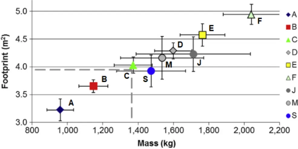
Vehicle segments in Europe do not have strict formal regulations. The definition is vague, and passenger vehicles are subdivided in 9 categories (A–F, J, M, S). In figure2.4, it is possible to correlate the mass with the vehicle segment. This dissertation focuses on small passenger vehicles (A and B segments), where Ford Fiesta, VW Polo, Fiat 500e and VW e-up! are well known examples [17, 18]. In table 2.1 the specifications of three vehicles (two ICE vehicles and one EV) from the same segment are presented.
Figure 2.4: Average footprint1over average mass per vehicle segment in the EU 2010 Note: The error bars around the averages represent the standard deviation [17]
2.2
Electrification
Electrification is the term appointed to a vehicle where electricity powers more than the 12-volt battery, present in every common vehicle, as well as basic accessories (e.g. radio,
1
footprint: vertical projection of the surface between the four wheels of the car 8
2.2. Electrification Table 2.1: Specifications for two ICE vehicles and the EV counterpart [19]
Parameter VW Up! (45 kW) VW Up! (56 kW) VW E-up!
Motor Gasoline (3 cylinders) Gasoline (3 cylinders) Electric
Max. Power (kW / rpm) 45 / 5000 – 6000 56 / 6200 61
Max. Torque (Nm / rpm) 95 / 3000 – 4300 95 / 3000 – 4300 210
Transmission 5 speed 5 speed 1 speed
Tare weight (kg) 940 940 1229
Top speed (km/h) 162 172 130 (limited)
Acc. 0–100 km/h (s) 14,4 13,5 12,4
Consumption 4,9 l/100 km (urban) 4,9 l/100 km (urban) 11,7 kW/100 km Autonomy (km) 650 (calculated) 650 (calculated) 160 (NEDC)
Price Portugal (e) 12 132 12 804 27 769
Price Germany (e) 10 425 11 900 26 900
Price Norway (e) 16 600 20 500 23 300
windows).
The efficiency of an ICE vehicle can be enhanced through engine improvement, transmission improvement, mild hybridization and use of lightweight materials. Taking only into consideration improvements on ICEs they are not sufficient to achieve future regulatory targets.
The elementary form of electrification can be seen in mild hybrid vehicles, where an electric machine is used as a generator which recovers braking energy (regenerative braking). This energy can be stored and, afterwards, applied in the electrical system or when accelerating the vehicle.
While the internal combustion engine technology is at full efficiency from upgrades throughout the last century, electrification is just in the beginning which grants room for improvement. Even though the ICE is at maximum performance, it cannot by itself meet current regulatory legislation established. This restraint associated with the high price of PEVs results in a need for electrification in the forthcoming years.
The main advantage of an electric drive is the capacity to generate high torque at low speeds, thus it is an ideal complement to an ICE since the torque is delivered at high speeds. The hybridization of a vehicle has the aim to perform always at optimum speed to reduce emissions and fuel consumption [20].
Companies in the automotive market, like BorgWarner, Bosch and Continental regard 48 Volt (V) mild hybridization as an impact technology in the near future and are working on solutions towards it. BorgWarner predicts that 48 V systems will impact more than 60 % of the global PHEV/HEV market in the next ten years. Examples of solutions in the BorgWarner’s portfolio are eBooster R electrically driven compressors and integrated
belt alternator starters (iBAS) which capture and handle waste energy in an efficient way contributing to a better efficiency and higher power [21]. Progress in fuel economy can be as high as 20 % depending on the application.
Bosch is investing in a 48 V battery that stores braking energy by means of a boost recuperation system (BRS). This energy is applied when the driver accelerates (electronic boost) which results in less fuel consumption and CO2 emissions [22]. Combined with the battery, Bosch has also designed a 48 V hybrid powertrain that, compared to other hybrid systems, is more economic. The additional 150 Nm of torque helps during acceleration and can reduce consumption up to 15 % [20].
2. Background Theory
Continental expects that electromobility is going to be vital in future mobility, hence the focus on electrification, particularly 48 V technologies. A decisive factor is the ease with which the 48 V belt starter generator integrates with the pre-existing ICE, because of the high power to size ratio of the electric motor. This small but powerful electric motor is viable since the stator is water cooled and has high efficiency. This technology is standard in recent models, Audi A8 and Renault Scénic, the latter has combined fuel consumptions of 3,5 liters (of diesel) per 100 km and CO2 emissions as low as 92 g/km [23,24].
2.3
Automotive industry
Nowadays, automakers are strongly dependent on base vehicle upgrades from costumers. There are several possible combinations, with different engines and transmissions as well as safety features and comfort upgrades (see figure2.5). The subsequent market for parts and services also plays a vital role in the revenue of OEMs.
Figure 2.5: Examples of sales prices in German market, e thousands (not including external incentives) [25]
As a result of base EVs being expensive it is common that a lot of safety and comfort features are already included. Moreover, EVs come with limited available configurations and the aftermarket maintenance is sparse and far economic, for consumers, compared to ICEs.
Native electric vehicle models have an indisputable advantage compared to models based on ICE. They can exploit new arrangements for the powertrain and battery pack and not be tied to the current disposition of components. This new approach leads to improved battery packaging culminating in extended range and more interior space [25].
The inferior complexity of electric relatively to ICE powertrains leads to exposure 10
2.4. Energy storage from OEMs which stand out through driving performance and creates an opportunity for suppliers and new OEMs to step up. As of today, Tesla and BYD (new competitors), are in the top 5 of EV manufacturers. While a PEV powertrain has around 200 components, an ICE one has 1400, additionally, the main components in a PEV (electric motor and battery packs) employ a highly automated process which is less dependent on labor [26].
Although automotive OEMs generally build and assemble engines and transmissions themselves, in this transition phase, most of PEV powertrains are acquired from suppliers due to inadequate production capacity and insufficient technological knowledge.
Europe OEMs are a good example, since they amount to one quarter (25 %) of worldwide ICE powertrain production, yet, regarding EVs, they outsource the electric motor, are dependent on battery suppliers and the Lithium-ion (present in most EV batteries) production is scarce (3 %) [26].
With this in mind, it is evident that, even though consumers still prefer to purchase an EV from leading manufacturers, EVs brought disruptive consequences to the automotive industry and there is an urgency for a new business model for automotive OEMs.
The automotive industry, to address these challenges, needs to connect the sequential product-development approach, developed in the last century, with a model like agile instead of a waterfall-based approach since it is faster and more iterative. It will have to collect and handle enormous amounts of data from consumers and vehicles to reimagine products and their production according to costumer’s desires (4.0 Industry). Due to the new unexplored technology, cooperation between the manufacturers is decisive to an active and robust progress in these still unfamiliar areas.
Key points for OEMs [4]:
• Collaboration with software manufacturers and map providers to create driving assistance systems and develop autonomous driving;
• Sustainability, use of renewable materials and life cycle assessment are of utmost importance;
• Electrification and electric vehicles developments, with strong focus in 48 V technologies and PHEVs, are already in motion, since, as it is perceived by OEMs, in the near future they will fully substitute conventional ICE vehicles;
• Accelerated changes in the market bring the need to introduce vehicles quickly, leading to a higher dependency in computer simulations;
• Developing countries such as Brazil, India and China play a crucial role in the future automotive market.
2.4
Energy storage
Energy storage systems follow a set of conditions in order to be applied in vehicles, specially electric vehicles. Specific energy2 and specific power3 (both characteristic of battery chemistry and packaging), efficiency and cost are the primary requisites which need to be taken into account when designing an electric vehicle battery. Specific energy
2
Nominal battery energy per unit mass (Wh/kg), it determines the weight required to achieve a given electric range.
3
Maximum available power per unit mass (W/kg), it determines the weight required to achieve a given performance.
2. Background Theory
is essential in PEVs considering it is directly associated to vehicle range. In HEVs, there is a focus in specific power to provide good vehicle performance [16].
In figure2.6and table2.2, there is a comparison between the most commonly employed energy storage devices in today’s vehicles.
Figure 2.6: Plot of a few electrochemical energy storage devices used in the propulsion application [7]
Table 2.2: Properties of several energy storage types [20]
Storage type Specific energy(Wh/kg) Energy density(Wh/L) Specific power(W/kg) Life cycles to80 % (charge-discharge) Lead-acid 20 – 35 54 – 95 250 800 Nickel-metal hydride (NiMH) 65 150 200 1000 Lithium-ion (Li-ion) 140 250 – 620 300 – 1500 >1000 Hydrogen fuel cell 400 – 650 – Ultra-capacitor 1 – 10 – 1000 – 10000 – 2.4.1 Battery
Batteries are the critical component in any EV; they must handle high power and high energy capacity while remaining at a reasonable price. Other relevant requirements are the weight and the limited space available. Despite the price decline (77 %) in recent years [6], battery is the component which pushes EVs price to a value higher than related ICEs.
2.5. Powertrain Lead-acid batteries have been used for more than a century and despite all the research in energy storage, they are still the best choice for low-voltage applications. Since they have low cycle life and low energy density, their use is prohibitive according to today EV’s requirements [7,27].
The dominant battery technologies used in today EVs are nickel metal hydride (NiMH) and lithium-based (Li), mostly lithium-ion (Li-ion). NiMH batteries are employed mainly in HEVs because of their low cost, high reliability and high durability.
Li-based batteries are employed in PHEVs and PEVs in virtue of higher energy density and specific energy, compared to NiMH, allowing a vital extended range. To ensure safety, battery management system (BMS) is always employed with these batteries [20,27].
For small passenger vehicles, typical battery properties values are: energy capacity 12 to 30 kWh, voltage 270 to 410 V, specific energy 55 to 100 Wh/kg. Battery cooling can be liquid, passive or by air [18].
2.4.2 Fuel cell
Unlike chemical batteries, fuel cells generates electric energy while fuel is supplied, instead of storing it in large quantities. Longer driving range, without time consuming charging time, puts fuel cell vehicles ahead of PEVs. Direct conversion to electric energy without combustion poses as an advantage towards ICEs. The most efficient fuel design employed in these vehicles is hydrogen, as fuel combined with oxygen.
Fuel cells are very reliable, with outstanding energy density and silent in operation but quite expensive to construct. Intricate storage and high pressure are the main problems that require development so that fuel cells can become a viable solution for energy storage. The access to hydrogen by consumers also lacks a favourable solution [20,28].
2.4.3 Ultra-capacitor
They are low-size and very high capacity capacitors. They can be charged in a very short period of time and the energy can also be used very quickly, for example, in fast acceleration.
In conventional vehicles, they can substitute large alternators for meeting intermittent high-peak power demands related to power steering and braking. They recover braking energy which usually dissipates as heat and it can be used to reduce losses in electric power steering [20].
2.5
Powertrain
Powertrain system of PEVs combine an electrical and a mechanical subsystem. The electrical system uses energy from the batteries to power one or more electric motors recurring to power electronics (e.g. converters, inverters). The mechanical system usually consists of a clutch, a transmission and a differential. Moreover, due to the favourable characteristic of the electric motor in respect to the torque-power curve desirable to run a vehicle, the restrictions around the ICE are not present anymore and several powertrain configurations are possible (see figure 2.7).
PEVs powertrain structures can be divided in two main classes – one-motor or two-motor based powertrains (see table2.3).
One-motor based powertrains have been adopted, preferentially, for commercial PEVs due to similarities with traditional ICEs where the transmission has been continually optimized, therefore requiring less overall modifications.
2. Background Theory
Figure 2.7: Six types of EV configurations [29]
Table 2.3: Categories of EV powertrain structures [29] One-motor based EV powertrains (see figure2.7)
(a) Conventional type:
The EV propulsion system consists of a differential (D), a gearbox (GB), a clutch (C) and an electric motor (M). This configuration can be considered as a counterpart of an ICE vehicle with rear-engine-front-wheel drive, where the ICE is replaced by an electric motor. (b) No transmission type: Rear-engine-Front-wheel (RF)
This configuration, with fixed gearing (FG) used instead of a clutch and gearbox, is quite similar as the conventional one.
(c) No transmission type: Front-engine-Front-wheel (FF)
The electric motor, fixed gearing and differential are placed together in the front, just like ICE vehicles with front-engine-front-wheel drives.
Two-motor based EV powertrains (see figure2.7) (d) No differential type:
Two electric motors are employed for individual front wheel to eliminate a differential. The two motors are connected to the front wheels through mechanical fixed gearing. (e) In wheel type with fixed gear (FG):
This type is similar to the no-differential type in (d), except different location of the electric motors. Electric motors are embedded in wheels for the in-wheel type.
(f) In wheel type without fixed gear (FG):
Mechanical gearing is completely removed for this type. The vehicle speed directly depends on the motor speed.
Two-motor powertrains identify themselves with simplified mechanical structures at the expense of complex electrical arrangements. The need for a differential can be eliminated, if each electric motor is independent and connected only to a single wheel.
2.5. Powertrain 2.5.1 Electric motor
Electric machines, in traditional vehicles, work as starters and alternators to provide the necessary energy for the engine to reach its idle speed and to any electric auxiliary loads (e.g. lights and radio). In electric vehicles, they are a fundamental component in the transmission.
An electric motor converts the electric energy, provided by the battery, into mechanical energy to move the vehicle. It can also work as a generator, harvesting the mechanical power from the transmission to recharge the battery and, in hybrid vehicles, convert the mechanical energy from the engine to electric energy which is delivered to the battery. Generally, they have a very wide operating range and, compared to ICE, are more efficient. The classic torque-power curve which an electric motor must follow is presented in figure 2.8, it can be divided in three essential stages – constant torque, constant power and high speed region.
Figure 2.8: Typical torque speed curve of an electric traction motor [30]
During the first stage, constant torque is applied until base speed is reached when inverter output voltage reaches its limit. The greater the constant torque phase, the higher the vehicle acceleration.
For the second stage, since the inverter is at both maximum voltage and current, it cannot deliver more power to the electric motor. So, to increase the vehicle speed beyond the base speed point, the output torque has to decrease by weakening the flux.
The last stage, high speed region, where vehicle speed is very high, the power cannot be kept constant and the inverter reduces the current provided to the electric motor [30]. Regarding small passenger PEVs, typical values for the electric motor are: maximum power 30 to 70 kW, maximum torque 130 to 200 Nm and maximum speed 7000 to 12 000 rpm [18,31].
Nearly all manufacturers adopt liquid cooling for the electric motors to avoid corrosion, overheating and freezing. The liquid usually consists of 50 % ethylene glycol and 50 % deionized water. Air and oil are also used, but in a very small scale [18].
Regardless of the type of electric motor, they all have two main components, the stator and the rotor. The rotor is linked to the output shaft where motor torque is generated.
2. Background Theory
Electric motors can be split into two main categories: alternating-current (AC) motors and direct-current (DC) motors.
Today, the main choice for PEVs is the permanent magnet synchronous machine (PMSM), which is a three-phase AC motor, because of its suitable properties related to efficiency, size and control simplicity [18,20,27].
Despite the dominance of PMSM in the EV industry, other relevant types of electric motors currently in use are induction motors (IM) and switched reluctance motors (SRM), see figure 2.9.
There are other arrangements worth mentioning such as DC motors, wound rotor synchronous motors (WRSM) and hybrid PMSM (synchronous reluctance machine with added permanent magnets).
Figure 2.9: Schematics of four types of motors:
Brushed DC motor (a), Permanent Magnet Synchronous Motors (b), Switched Reluctance Motor (c), Induction Motor (d). Adapted from [27]
Originally, DC motors were the preferred choice because of its control simplicity, decoupling of flux and torque and the unnecessary need of an inverter. Drawbacks like maintenance (brushes and rings) and low efficiency have led to its discontinuity. WRSM have the advantage of reducing starting current and increasing starting torque, but they require maintenance (brush gear) and are expensive. Hybrid PMSM brings a boost to base torque as well as an increased efficiency and power, which remains constant until maximum speed. Torque ripple and low power factor come up as disadvantages [27,32,33].
Permanent Magnet Synchronous Motor (PMSM)
The main advantages of PMSMs are higher efficiency, specific power and power density. They also are more compact than induction motors. However, a small constant power
2.5. Powertrain region is associated with these motors. Controlling the conduction angle of the power converter at speeds higher than the base speed4, it is possible to increase the efficiency and widen the speed range. It can be extended to three or four times the base speed. One of the drawbacks is the possibility of demagnetization due to armature reaction or excessive heat.
Brushless DC motors (BLDC) are often confused with PMSM since they are identical in respect to the torque generation principle. Both are synchronous machines that perform the excitation of the rotor through permanent magnets. The main difference is the waveform of the stator currents – rectangular in BLDC and sinusoidal in PMSM [20,28]. Some recent EVs have interior mounted magnets instead of being at the rotor surface, this provides several advantages such as higher torque (additional reluctance torque) and the magnets are protected against centrifugal force allowing higher rotational speed.
PM motors can also be classified with respect to the magnetic flux – radial flux, axial flux or transverse flux. While radial flux motors are the most common, axial flux ones are getting traction and are easily integrated as in-wheel motors due to the reduced axial dimension. Transverse flux PM motors are still in development phase, so, they are quite inexpressive in the electric vehicle automotive industry [27,32,33].
Induction Motor (IM)
The IM are asynchronous AC motors and have been increasingly endorsed by OEMs because of the cost liability of rare-earth elements, present in the magnets, which have seen an increase in price due to high demand and scarcity. They can have a wound rotor but, frequently, the squirrel cage is chosen since it is more reliable, robust and requires almost no maintenance.
Tesla vehicles, Roadster and Model S, use these motors since with high power rating they achieve higher performance, and the torque and speed can be controlled more smoothly, providing more stability and comfort.
Disadvantages consist of break-down torque (in the constant power region), inferior efficiency compared to PMSM and low power factor [18,27,32].
Switched Reluctance Motor (SRM)
SRM motors are presently perceived by OEMs as a possible future solution. In general, they are known for its simple control and construction, fault tolerance, high efficiency and intrinsic wider constant power region. They possess, as well, an excellent torque-speed characteristic and can work at high temperatures and great rotational speed. Like for induction motors, there is no need for rare earth magnets and the drawbacks associated with its use.
Some obstacles still need to be surpassed like significant torque ripple and electromagnetic interference. In virtue of more accurate switch control, the high noise problem is already solved [20,28,32].
Comparison
The brushed DC motor, despite starting the EV era due to its advanced technical maturity and low cost, provides the lowest power density, inadequate reliability and it has poor efficiency. As already stated, it also requires maintenance. All these faults led to a search for new solutions and, ultimately, to its obsolescence in the EV industry.
4
2. Background Theory
PMSM, due to the highest power density – highest power for the same motor weight – among the mentioned EM, leads the EM market for EVs. It has the maximum efficiency in a limited speed range (generally at low speeds), hence its use in small passenger vehicles (A – B segment) which are mainly used in city traffic conditions.
At low production costs, the finest reliability and best overall efficiency over the entire speed range are characteristics of the IM machine. It is the preferred choice when one of the requisites is good efficiency over a wide speed range (vehicles in segments C to F, for example, Mercedes-Benz B-Class, Toyota RAV4 and Tesla S [18]). As main disadvantages, conservative power density and field oriented control, significant costs drive away the low-end vehicle market off.
SRM machine is similar to IM regarding efficiency and power density. However, as previously indicated, high torque ripple (at low speeds) still is an exclusion criterion for most manufacturers [34].
In table2.4is presented a comparison between the electric motors commonly adopted by OEMs, which provides a clear view over the most significant properties, and the efficiency maps of figure2.10 confirm the segment market tendencies.
Table 2.4: Evaluation of four electric machine types [34]
2.5.2 Transmission
Transmission is a key component in vehicles, its main function is to transmit power from the engine to the wheels, it converts torque and engine speed so that the vehicle performance requisites are achieved. There is a wide variety of transmission configurations – manual, automatic, continuous variable transmission (CVT) which can be further subdivided. Major components commonly present in transmission include: clutch, gearbox, differential and drive shaft [35].
Due to its features and importance, transmissions are inherently related to "fuel" consumption, reliability and ease of operation. All these points play a crucial role in today’s automotive industry and, while simple innovations are not likely to happen, there is a strong urge in electronic transmission control to reach improved operation.
In conventional ICEs, considering the engine characteristics, a manual or automatic transmission with a considerable amount of speeds is required to effectively deliver torque and power. EVs, which depend on an electric drive (like PEVs), have, at most, a two-speed transmission, hence reducing energy losses through gear-shifting.
Predominantly, in PEVs, a single speed transmission is employed which turns the clutch dispensable. The common transmission ratio range of latest PEV models, with one electric motor, is between 7 and 10 [18].
2.5. Powertrain
Figure 2.10: Exemplary efficiency maps of different electric motors with constant power [34]
Fixed ratio single speed transmission
This transmission (see figure 2.11) is the most widely used system in behalf of structure simplicity and the remarkable effectiveness of the electric motor over combustion engines, namely, high stall-torque5 and ability to deliver constant power in a wide speed range. Additionally, it provides a pleasant driving experience at an affordable price [36, 37]. Despite being adequate for the majority of vehicles, gear ratio design is a commitment between range, performance (for example: stall torque) and top speed desired.
Figure 2.11: Single speed transmission in a PEV powertrain. S1, S2 – shafts [37]
Two speed transmission
Even though, multi-speed transmissions typical drawbacks, such as increased cost and mass, decreased efficiency and torque interruption when gear shifting, suggest that they are counter-productive for electric vehicles, innovative arrangements can offer advantages over single transmissions.
5
2. Background Theory
Two speed transmission provide higher wheel torque at low rpm, consequently, the electric motor stall torque may be inferior resulting in a smaller motor. Global efficiency increases leading to extended driving range. Moreover, acceleration and gradeability increase as well. Finally, the presence of a second gear allows a superior vehicle top speed [36,38].
One of the innovative structures uses a dual clutch system (see figure 2.12). The use of two clutches facilitates the torque transference, overcoming the torque interruption problem. Since there are only two speeds, each clutch is connected to each speed directly, therefore there is no need for a synchronizer and its control. The extra gear set and clutches have a negative effect in efficiency and overall mass [37].
Figure 2.12: Two speed dual clutch transmission in PEV powertrain. S1, S2, S3 – shafts. C1, C2 – clutches [37]
The twinspeed transmission (see figure 2.13) has two integrated planetary gear sets, one selectable clutch and a single stage final drive (with differential). It has a shift strategy implemented which results in an excellent combination of efficiency and performance. In general, it increases the effective area of high efficiency in actual driving [36].
Figure 2.13: Twinspeed transmission with two planetary gear sets. 1 - Two integrated planetary gear sets, 2 Single stage final drive, 3 Controlled dry friction brake, 4 -Selectable dog clutch, 5 - Differential gear [36].
Continuously Variable Transmission (CVT)
CVT (figure 2.14) has an infinite number of ratios (between the stipulated limits) and the unique possibility to alter gear ratios without power flow interruption. Usually a CVT has a steel belt which connects two variable diameter pulleys, the transmission ratio
2.5. Powertrain changes with the adjustment in pulley diameter, allowing the best possible speed over the whole vehicle driving range ensuing higher motor efficiency [37]. Another convenience is the potential to decouple top speed and acceleration, ultimately leading to improved performance.
However, extra weight and manufacturing costs need to be considered when designing such a transmission.
Figure 2.14: Continuously variable transmission with servo-electromechanical actuation system [37]
2.5.3 Differential
All vehicles need some sort of differential. It is indispensable when turning a vehicle. To safely turn, the outside wheels must spin faster than the inside wheels, which is provided by the differential. At the same time, they act as the final gear reduction in a vehicle and transmit the power to the wheels.
There are several types of differentials, designed for certain conditions, such as on and off-road driving. The most common is an open differential which is preferred in normal road conditions, but if one wheel loses traction, it will send all the power to the wheel with the least resistance. Locking differential works as an open differential, but if locked it locks the axle resulting in equal torque being sent to each wheel [39].
Limited slip differential (LSD) works as a trade-off between the open and the locking differential. It limits the difference in rotational wheel speed to counter the problem where all power goes to one wheel. Within LSDs, one particular example is the electronic limited slip differential which determines the ideal amount of torque needed for the given driving conditions through the vehicle’s engine unit [39].
Most vehicles have a front-mounted engine, which leads to a preferred front-wheel drive (see figure2.15) due to its lighter weight, and predictable handling characteristics. In these vehicles, the differential is interconnected with the reducer having a simpler design and sparing the need for a drive shaft and/or center differential.
Today, rear-wheel drive (see figure2.16) vehicles are found in sports and luxury cars. A good example is the automotive company BMW. Despite being more complex systems, the precise handling performance is still a decisive point for some costumers. When connected to a front-mounted engine, a drive shaft and rear differential are required. The rear differential is very similar to a front differential, yet it cannot be coupled with the reducer, leading to more components, complexity and lower efficiency.
![Figure 2.1: Historical fleet CO 2 emissions performance and current standards for passenger cars (gCO 2 /km normalized to NEDC) [2]](https://thumb-eu.123doks.com/thumbv2/123dok_br/15677698.1063016/32.892.212.769.132.455/figure-historical-emissions-performance-current-standards-passenger-normalized.webp)
![Figure 2.6: Plot of a few electrochemical energy storage devices used in the propulsion application [7]](https://thumb-eu.123doks.com/thumbv2/123dok_br/15677698.1063016/38.892.217.767.236.557/figure-plot-electrochemical-energy-storage-devices-propulsion-application.webp)
![Figure 2.8: Typical torque speed curve of an electric traction motor [30]](https://thumb-eu.123doks.com/thumbv2/123dok_br/15677698.1063016/41.892.128.688.438.753/figure-typical-torque-speed-curve-electric-traction-motor.webp)
![Figure 2.10: Exemplary efficiency maps of different electric motors with constant power [34]](https://thumb-eu.123doks.com/thumbv2/123dok_br/15677698.1063016/45.892.190.623.125.468/figure-exemplary-efficiency-different-electric-motors-constant-power.webp)
![Figure 2.15: Typical front-wheel drive powertrain components: in an ICE vehicle (left) [40] and in a PEV vehicle (right) [20]](https://thumb-eu.123doks.com/thumbv2/123dok_br/15677698.1063016/48.892.172.799.134.336/figure-typical-wheel-drive-powertrain-components-vehicle-vehicle.webp)
![Figure 2.17: GETRAG 1eDT330 electrical transmission with independent transmission components and electric motors [43].](https://thumb-eu.123doks.com/thumbv2/123dok_br/15677698.1063016/49.892.214.588.133.371/figure-getrag-electrical-transmission-independent-transmission-components-electric.webp)
![Figure 2.20: Schematic design of the drive train (left) and gear set (right) [47].](https://thumb-eu.123doks.com/thumbv2/123dok_br/15677698.1063016/50.892.235.744.807.1077/figure-schematic-design-drive-train-left-gear-right.webp)
![Figure 3.1: Torque-power peak curve of the Zytek 25 kW electric motor [52]](https://thumb-eu.123doks.com/thumbv2/123dok_br/15677698.1063016/54.892.249.734.478.794/figure-torque-power-peak-curve-zytek-electric-motor.webp)
![Figure 3.2: Forces acting on a vehicle moving uphill [16]](https://thumb-eu.123doks.com/thumbv2/123dok_br/15677698.1063016/56.892.248.746.130.447/figure-forces-acting-vehicle-moving-uphill.webp)
