Universidade de Aveiro Departamento de Eletrónica,Telecomunicações e Informática
2019
SANDRA INÊS
FERREIRA MOREIRA
Integração Contínua no 5GinFIRE
“It takes a lot of hard work to create something simple.”
Universidade de Aveiro Departamento de Eletrónica,Telecomunicações e Informática
2019
SANDRA INÊS
FERREIRA MOREIRA
Integração Contínua no 5GinFIRE
Universidade de Aveiro Departamento de Eletrónica,Telecomunicações e Informática
2019
SANDRA INÊS
FERREIRA MOREIRA
Integração Contínua no 5GinFIRE
5GinFIRE Continuous Integration
Dissertação apresentada à Universidade de Aveiro para cumprimento dos requisi-tos necessários à obtenção do grau de Mestre em Engenharia de Computadores e Telemática, realizada sob a orientação científica do Doutor Diogo Nuno Pereira Gomes, Professor auxiliar do Departamento de Eletrónica, Telecomunicações e Informática da Universidade de Aveiro, e do Doutor Rui Luís Andrade Aguiar,
Pro-o júri / the jury
presidente / president Prof. Doutor Paulo Miguel Nepomuceno Pereira Monteiro
professor associado do Departamento de Eletrónica, Telecomunicações e Informática da Univer-sidade de Aveiro
vogais / examiners committee Prof. Doutora Ana Cristina Costa Aguiar
professora auxiliar da Faculdade de Engenharia da Universidade do Porto
agradecimentos /
acknowledgements Em primeiro lugar, gostaria de agradecer ao Prof. Doutor Diogo Gomes e aoProf. Doutor Rui Aguiar pela oportunidade de desenvolver este trabalho e por todo o apoio prestado ao longo da evolução do mesmo. Aproveito também para agradecer ao IT (UID/EEA/50008/2019) por fornecer os recursos e condições para a realização desta Dissertação.
Um grande agradecimento aos meus pais e irmãos, a quem dedico este trabalho, por serem sempre os primeiros a acreditarem em mim, estarem sempre disponíveis e fornecerem todas as condições para que fosse possível percorrer este caminho. Por último, agradeço a todos os meus amigos pelo companheirismo e amizade, em particular ao Jaime, ao Ricardo e ao Marco por estarem sempre disponíveis para
Palavras Chave nfv, osm, integração contínua, validação de descritores do osm
Resumo Com a evolução dos equipamentos com capacidade de se ligar à rede, as exigências de tráfego tornam-se muito altas. Os operadores precisam de garantir que oferecem os seus serviços rapidamente, com a mesma qualidade, mas mantendo os custos baixos. Dada a arquitetura tradicional de redes, isso não é possível uma vez que para alcançar essas necessidades é fundamental a aquisição de novos equipamentos, sendo que a sua substituição é cara e pouco flexível. Com a proposta de separação de funções de rede do seu hardware específico, NFV é a tecnologia que permite aos operadores alcançar o pretendido. No entanto, esta abordagem traz consigo problemas relacionados com a fiabilidade do código produzido, uma vez que é imperativo assegurar que as funções de rede implementadas (VNFs) se comportam como esperado. O 5GinFIRE é um projeto que tem como objetivo manter uma plataforma de experimentação de 5G-NFV. Como este projeto lida com múltiplas VNFs de vários colaboradores, é necessário haver um mecanismo automatizado que valida as mesmas. Esta dissertação aborda a solução referenciada tendo em si descrito um sistema que valida a sintaxe, semântica e referências de uma VNF de uma forma totalmente automatizada e sem qualquer necessidade de intervenção
Keywords nfv, osm, continuous integration, osm descriptors validation
Abstract With the current evolution of network connectable devices, traffic demands are becoming very high. Network operators need to ensure that they can provide new services faster but with the same quality while keeping the costs low. Given the traditional network architecture, that is not possible because the high demands re-quire new hardware, and its substitution is costly and not flexible. By introducing the decoupling of network functions from traditional hardware, NFV is the technol-ogy that enables the step that network operators are trying to take. However, this approach also brings reliability concerns since it is mandatory to ensure that the virtual network functions (VNFs) behave as expected. 5GinFIRE is a project that aims to provide a 5G-NFV enabled experimental testbed. As this project handles multiple VNFs from the various experimenters, it is necessary to have an automated mechanism to validate VNFs. This dissertation provides a solution for the stated problem by having a system that verifies the syntax, semantics, and references of a VNF in an automated way without needing any further human interaction. As a
re-Contents
Contents i
List of Figures v
List of Tables vii
Acronyms ix 1 Introduction 1 1.1 Motivation . . . 2 1.2 Goals . . . 2 1.3 Dissertation structure . . . 3 2 Background concepts 5 2.1 Traditional networks architecture . . . 5
2.1.1 Current architecture problems . . . 6
2.2 Network Function Virtualization . . . 7
2.2.1 Virtual Network Function . . . 9
2.2.2 Network Service . . . 9
2.2.3 Network Function Virtualization Infrastructure . . . 9
2.2.4 Network Function Virtualization Management and Orchestration . . 10
2.3 Open Network Automation Platform . . . 12
2.4 Open Baton . . . 12
2.5 SONATA . . . 13
2.6 Open Source Mano . . . 13
2.6.1 Open Source Mano (OSM) Virtual Network Function (VNF) . . . 15
2.6.3 OSM Information Model (IM) . . . 16
2.6.4 JuJu Charms . . . 23
2.6.5 Open Source Mano architecture . . . 25
2.7 5GinFIRE . . . 28 2.8 DevOps . . . 31 2.8.1 Continuous Integration . . . 33 2.9 Related work . . . 33 2.9.1 5GTango . . . 33 2.10 Summary . . . 34
3 Architecture and Specifications 37 3.1 Problem statement . . . 37
3.2 Requirements and specifications . . . 38
3.2.1 Validation scripts . . . 38
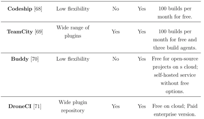
3.2.2 Selection of the Continuous Integration (CI) server . . . 39
3.2.3 Jenkins . . . 41 3.3 Proposed solution . . . 42 3.3.1 Architecture . . . 43 3.4 Summary . . . 45 4 Implementation 47 4.1 OSM IM Wrapper . . . 47
4.2 VNFD and NSD models class . . . 49
4.3 Tests . . . 50 4.3.1 Syntactic validation . . . 50 4.3.2 Semantic validation . . . 51 4.3.3 Reference validation . . . 54 4.3.4 NS over VNF validation . . . 56 4.3.5 osm-descriptor-validator . . . 57
4.4 Jenkins, osm-descriptor-validator and 5GinFIRE integration . . . 58
4.4.1 5GinFIRE integration . . . 58
4.4.2 Jenkins configuration . . . 59
4.5 Summary . . . 63
5 Results 65 5.1 Scenarios . . . 65 5.2 Data Gathering . . . 67 5.3 Results . . . 67 5.4 Summary . . . 78 6 Conclusions 79 6.1 Future work . . . 80 References 81
List of Figures
2.1 Transition to Network Function Virtualization (NFV)[11]. . . 8
2.2 European Telecommunications Standards Institute (ETSI) NFV architectural reference[16]. . . 9
2.3 Virtualized resources provided to VNFs [11]. . . 10
2.4 ETSI NFV Management and Orchestration (MANO) main components [20]. . . 11
2.5 Comparison between ETSI NFV MANO architectural specification [16] (left) and OSM (right) [28]. . . 14
2.6 VNF package structure tree. . . 15
2.7 NS package structure tree. . . 16
2.8 Difference between the elements designations in OSM IM. . . 17
2.9 Virtual Network Function Descriptor (VNFD) structure tree. . . 17
2.10 Hackfest basic VNF diagram. . . 20
2.11 Network Service Descriptor (NSD) structure tree. . . 21
2.12 Hackfest basic NS diagram. . . 23
2.13 Charm new layer structure. . . 25
2.14 Charm new layer after building. . . 25
2.15 OSM architecture [38]. . . 26
2.16 Interaction between OSM modules over the deployment of NSs and VNFs [29]. . 27
2.17 5GinFIRE architecture [8]. . . 29
2.18 5GinFIRE colaborators and their purposes (adapted from [41]). . . 30
2.19 DevOps different components. . . 32
3.1 osm-descriptor-validator architecure. . . 43
3.2 Deployment architecture of the automated solution. . . 45
4.2 Syntactic test workflow. . . 51
4.3 Semantic test workflow. . . 53
4.4 Reference validation workflow. . . 54
4.5 Second loop workflow. . . 55
4.6 Manipulation of the tuples in verify_references. . . . 56
4.7 Sequence of events between 5GinFIRE and the Jenkins pipeline. . . 62
5.1 5GinFIRE’s Jenkins dashboard. . . 66
5.2 5GinFIRE’s VNF developer scenario. . . 66
5.3 Independent VNF developer scenario. . . 67
5.4 Distribution of errors and warnings according the reasons. . . 69
5.5 Distribution of tags with errors. . . 70
5.6 Distribution of warnings according the reasons. . . 71
5.7 Distribution of the number of warnings per file. . . 72
5.8 Number of errors and warnings from each of the used tags. . . 73
5.9 Distribution of errors and warnings from each of the used tags. . . 73
5.10 Difference between the tags usage between charmed and non-charmed descriptors. 74 5.11 Jaccard index distribution when the dataset is compared with the reference VNFD. 76 5.12 Matrix with distribution of the Jaccard Index between all the descriptors. . . 77
List of Tables
2.1 VNF possible configurations overview. . . 19
2.2 NS possible configurations overview. . . 22
2.3 Possible roles on the 5GinFIRE environment [9], [40]. . . 30
3.1 Performance of the different CI servers over the established requirements. . . 41
5.1 Pipeline results from September to October 2019. . . 68
5.2 Validation results from osm-descriptor-validator. . . 68
Acronyms
5G Fifth Generation of Cellular Mobile
Communications
API Application Programming Interface AWS Amazon Web Services
CD Continuous Delivery CI Continuous Integration CLI Command Line Interface CM Continuous Monitoring COTS Commercial off-the-shelf CPU Central Processing Unit CT Continuous Testing
ETSI European Telecommunications
Standards Institute
EVI Experimental Instances of Verticals GUI Graphical User Interface
IM Information Model IoT Internet of Things
ISG Industry Specification Group JSON JavaScript Object Notation LCM Lifecycle Manager
MANO Management and Orchestration MON Monitoring Module
NBI Northbound Interface
NFVI Network Function Virtualization
Infrastructure
NFVO Network Function Virtualization
Orchestrator
NFV Network Function Virtualization NF Network Function
NSD Network Service Descriptor NSR Network Service Record NST Network Slice Template NS Network Service
NVI Network Virtualized Infrastructure ONAP Open Network Automation Platform OSM Open Source Mano
OSS Operational Support System POL Policy Manager
REST Representational State Transfer RO Resource Orchestrator
SCM Source Code Mananagement SDK Software Development Kit SDN Software-Defined Network SFC Service Function Chaining SNMP Simple Network Management
Protocol
UI User Interface
VCA VNF Configuration and Abstraction vCPE Virtual Customer Premises
Equipment
VDU Virtual Deployment Unit VIM Virtual Infrastructure Manager VLD Virtual Link Descriptor
VL Virtual Link
VM Virtual Machine
VNFD Virtual Network Function
Descriptor
VNFFG Virtual Network Function
Forwarding Graph
VNFM Virtual Network Function Manager VNFR Virtual Network Function Record VNF Virtual Network Function
VoLTE Voice over Long Term Evolution YAML YAML Ain’t Markup Language YANG Yet Another Next Generation
CHAPTER
1
Introduction
In 2017, mobile connectivity rose by 71 percent [1]. By 2022, worldwide mobile traffic will reach 77 exabytes per month. That means nearly one zettabyte per year. These numbers are anticipated since society has evolved in a way where one person uses multiple internet-connected devices. Furthermore, the rise of Internet of Things (IoT) also contributes to the increase in traffic since devices and services that used to be offline are now online, such as cars, sensors, robots, and services like immersive media application, smart-manufacturing, surveillance, among others. These services, which nowadays include a lot of heavy traffic operations like video streaming, rely a lot on the network infrastructure for their connectivity needs [2]. This necessity makes the verticals the key drivers of Fifth Generation of Cellular Mobile Communications (5G) networks adoption [3]. 5G networks need to have high bandwidth, low latency, low power consumption and be cost-effective to meet the traffic and vertical demands [4]. In order to reach these requirements, it is necessary to change the network paradigm and start not relying on the manufacturers’ hardware.NFV is of interest to network operators and providers because it facilitates the development of new mechanisms for the delivery and maintenance of network and infrastructure services [5] [6]. NFV provides the decoupling of Network Function (NF) from manufacturers’ hardware by providing the service through software running on Commercial off-the-shelf (COTS) devices. The services are then deployed through VNFs, which can be tailored and adjusted to any demands. However, the migration of hardware-based functions to software raises concerns about software reliability [4], since it is necessary to ensure that the VNFs behave as expected. Consequently, one of the biggest challenges is the validation of VNFs and NSs [7].
Projects like 5GTango1 try to tackle this problem by having a full Software
velopment Kit (SDK) that validates VNFs and NSs. However, the platform requires high customization, and its integration with other projects is not straightforward. It is, therefore, possible to make improvements.
1.1 Motivation
5GinFIRE2 is a project funded by the European Horizon 2020 Programme with several
partners from all around the world. Its main objective is to provide a 5G NFV enabled experimental framework able to instantiate and support vertical industries while using leading and open source technologies [8]. Identifying itself as a "forerunner experimental playground" [9], 5GinFIRE relies on its experiments to validate the infrastructure. Making sure everything runs evenly is therefore mandatory to have a reliable unified testbed. The experiments are activities that are conducted over the 5Ginfire environment and make use of NSs. These NSs are composed of VNFs, which have to be previously submitted on the 5GinFIRE portal.
A crucial step to take is to guarantee that the packages submitted are well built and ready to be deployed on the orchestrator. Currently, the validation is being carried out manually by the 5GinFIRE portal administrator. However, such a solution is neither sustainable, scalable, or practical. These constraints lead to the necessity of having a fully automated validation [10].
1.2 Goals
The focus of this Dissertation is to provide a tool that allows validation of VNFDs and NSDs. The tool should grant quick debugging by providing explicit and direct logs with enough information to identify errors easily. Moreover, it should not require much configuration and should be lightweight.
A CI server should be deployed and integrated with the 5GinFIRE infrastructure. Subsequently, CI pipelines should be configured on the framework in order to call the validation tool and automate its usage. In the end, it is expected that the pipeline is triggered whenever a developer submits a new VNF in the portal, and the produced tests are performed over the VNFD.
Nevertheless, the developed solution must be independent of the CI server so that it can be used in other situations, for example, without automation associated or with another server.
2https://5ginfire.eu/
1.3 Dissertation structure
To make the reader acquainted with the most relevant concepts of this document, Chapter 2 describes the necessary background as well as related work. Chapter 3 provides the requirements needed in order to build a solution as well as a full description of its architecture. Afterward, Chapter 4 gives a comprehensive overview of the system implementation, which includes either the package development as well as the integration with the automation platform. Next, Chapter 5 is presented, which lays out the analysis of the results gathered. Finally, Chapter 6 provides the work conclusion. Lastly, the references are presented.
CHAPTER
2
Background concepts
This chapter gives an overview of all the concepts that are important for understanding this Document. With the primary goal of this Dissertation being the creation of a mechanism to validate OSM VNFs and NSs and integrate it with 5GinFIRE, it was first necessary to understand the 5GinFIRE scope and then learn about automation techniques.
5GinFIRE is a project that aims to provide an open and extensible testing platform for NFV related experiments. Therefore, the first section of this chapter addresses NFV by exposing the reasons for its development and a description of its architecture.
One of the main components of NFV is MANO. Many entities have made efforts do de-velop their MANO implementation. In particular, SONATA, Open Network Automation Platform (ONAP), Open Baton and OSM are the most popular projects. The first three have a dedicated section with a brief description of their characteristics. A more detailed study is provided for OSM since it is the orchestrator used by 5GinFIRE. With the clarification of these concepts, the next section describes the 5GinFIRE architecture and the project workflow. The last two sections address the DevOps and CI concepts, which are fundamental understanding the automation concept followed on this Dissertation.
2.1 Traditional networks architecture
The traditional network system has always been approached as a physical equipment world. Throughout the years, networks have become quicker, more capable, and resilient; however, they are still struggling to meet the evolving market requirements [11]. For network operators, deploying a new service involves purchasing new physical equipment for each of its features. This approach leads to a set of problems for service providers. [11] gives an in-depth overview of those difficulties, which are described in section 2.1.1.
2.1.1 Current architecture problems
Flexibility
Network operators rely on proprietary equipment. This equipment is usually bundled as one - hardware and software - and limited to the vendors’ implementation. This approach leads to a limitation of flexibility and customization of such devices.
Scalability
Being dependent on physical network equipment raises problems on space availability and power consumption. Software-wise, these devices are designed to handle limited data. Once that cap is reached, operators have no options rather than upgrading the device.
Time-to-Market
With the evolution of applications, new services often grow on requirements. So, to implement new services and meet their demands, buying new networking equipment and redesigning the network are challenges that operators have to go through. Service providers are, therefore, delaying the launch of new services, resulting in company and revenue losses.
Manageability
Although networks implement standardized monitoring protocols such as Simple Network Management Protocol (SNMP), Netflow1, or Syslog2, vendor-specific parameters are
usually monitored using non-standard tools. Thus, with the different variety of devices and vendors, monitoring and controlling logs may become too overwhelming.
High Operational Costs
As previously stated, buying new equipment to sustain new services is expensive. Besides, manufacturers require highly trained staff to deploy and maintain their devices, contributing to the raise of additional costs.
Migration
Considering the situations when no new services are to be launched, after some time, networks and devices have to be upgraded and reoptimized. This update includes on-site physical access and workers to deploy new equipment, reconfigure connectivity, and enhance site infrastructure.
1https://www.cisco.com/c/en/us/products/ios-nx-os-software/ios-netflow/index.html 2https://tools.ietf.org/html/rfc5424
Operators need to find a way of providing their services with the same quality while keeping the costs low. NFV was proposed to mitigate the identified challenges. Section 2.2 presents a more in-depth description of this technology.
2.2 Network Function Virtualization
NFV’s main idea is to isolate physical network equipment from the service running on it. With this approach, it is possible to centralize network devices on COTS hardware. COTS are equipment for general use that do not require the adoption of proprietary hardware or software. These types of devices are, for example, servers, switches, or storage. Network services are then developed in software that is compatible with the referred equipment [5]. The resources are sufficiently abstracted for network services to make use of them without knowing their location and organization.
This cloud model paradigm is about improving how to implement and control network services; therefore, NFV promises to deliver agile operations, quicker role creation, and efficient use of resources.
In the end, NFV differs from the current network practices mainly in three aspects [12], [13]: (i) it decouples software from hardware, which allows the network service to not be a combination of interconnected hardware and software, making these components independent of one another; (ii) enables flexible network function deployment because, as software is detached from hardware, there is more room to combine these components and performing different network functions faster over the same physical platform; and, as a consequence of the described characteristics, (iii) it allows dynamic scaling because as the network function is instantiable software, it is then easier to scale its performance more dynamically. Figure 2.1 pictures the changes on the migration from traditional networks to NFV.
Currently, the entity responsible for the standardization and development of NFV in Europe is ETSI. To guide the research on this field, ETSI created an Industry Specification Group (ISG) for NFV. ETSI NFV ISG was created in 2012 by seven leading telecommunication operators [14]. Since then, the group released over eighty different documents that cover all the architecture specifications, requirements as well as functional components, their interfaces, Application Programming Interfaces (APIs), and protocols [15].
NFV is intended to address the demands of flexibility, agility, and scalability [2]. The goals of NFV proposed by ETSI are [12]:
• Use COTS hardware to deploy NFs through software virtualization. These NFs will then be called VNFs.
Figure 2.1: Transition to NFV[11].
• Improve scalability and decouple functionality from location by boosting flexibility in assigning VNFs to hardware. This approach makes it possible to store software at the most appropriate locations, such as data centers.
• Fast service upgrades through software-based service deployment.
• Reduced power consumption accomplished by moving workloads and shutting unused hardware down.
• Standardized and open interfaces between the VNFs, the infrastructure, and the management entities so that different vendors can supply these decoupled components.
In order to achieve the stated goals, ETSI built NFV architecture displayed on figure 2.2.
The referenced diagram shows three main components: the Virtual Network Func-tion, the Network Function Virtualization Infrastructure and the Network Function
Computing
Hardware HardwareStorage HardwareNetwork Hardware resources
Virtualisation Layer InfrastructureVirtualised Manager(s) VNF Manager(s) NFV Orchestrator OSS/BSS NFVI VNF 3 VNF 1
Execution reference points Other reference points Main NFV reference points Virtual
Computing StorageVirtual NetworkVirtual
NFV Management and Orchestration
EM 2 EM 3 EM 1 Or-Vi Or-Vnfm Vi-Vnfm Os-Ma Ve-Vnfm Nf-Vi Vn-Nf Vl-Ha Service, VNF and Infrastructure Description VNF 2
Figure 2.2: ETSI NFV architectural reference[16].
Virtualization Management and Orchestration. A full description about these compo-nents based on [11] and [12] is provided in the next following sections.
2.2.1 Virtual Network Function
A VNF is the software virtualization of a NF that can be deployed in a Network Function Virtualization Infrastructure (NFVI) [17]. This NFV component aims to perform the actions of a network device such as routers, switches, firewalls, among others, through software while operating on generic hardware. VNFs use Virtual Machines (VMs) to deploy their software. The VMs are provided by the NFVI. When two or mone VNFs are connected they form a NS.
2.2.2 Network Service
A NS is a group of VNFs described by their functional and behavioral characteristics [17]. NS’ objective is to describe the relationship between its constituent VNFs and the links that connect them in the NFVI network. Such connections link VNFs to connection points that provide an interface to the existing network [18].
2.2.3 Network Function Virtualization Infrastructure
NFVI is the combination of hardware and software components that build up the environment where VNFs are deployed [17]. Given that description and figure 2.2,
NFVI is composed by COTS, a virtualization layer (which may be, for example, an hypervisor) and virtual resources.
For ETSI, hardware resources, which, as referred above, are COTS, are of three types: computing, storage, and network. Computing resources include both Central Processing Unit (CPU) and memory; storage may be network-attached or local storage; network hardware includes the network interface cards and ports.
The virtualization layer is responsible for abstracting the hardware resources as well as isolating the VNF software from them. Furthermore, this layer communicates directly with the hardware resources making them accessible for the VNF as a VM. In the end, this layer is the component that decouples the software from the hardware.
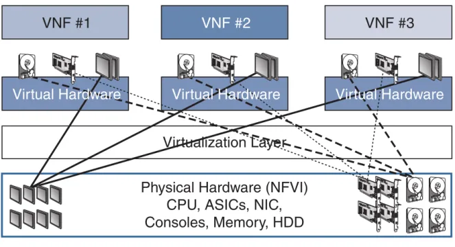
Figure 2.3 displays the communication provided by the virtualization layer between the physical hardware and the VNFs.
Figure 2.3: Virtualized resources provided to VNFs [11].
2.2.4 Network Function Virtualization Management and Orchestration
NFV MANO covers all the orchestration and lifecycle management operations of the physical and software resources as well as the VNF’s. There are three functional blocks on the NFV MANO framework and four data repositories. As it is portrayed on figure 2.4, the functional blocks are the Network Function Virtualization Orchestrator (NFVO), the Virtual Network Function Manager (VNFM) and the Virtual Infrastructure Manager (VIM) and the repositories are the NS catalog, VNF instances, NS catalog and NFVI
resources [19], [20].
The mentioned repositories handle all data from the ETSI NFV framework. Each database has a specific function and targets other framework components [20].
The NS catalog is a collection of predefined models that describe how to build and deploy services as well as its functions and their connectivity. On another hand, the VNF catalog is a compilation of models detailing the deployment and functional features of the VNFs available. The NFVI resources repository holds information on the availability of the NFVI resources. Last but not least, the NFV instances repository stores lifetime data on all function and service instances.
Figure 2.4: ETSI NFV MANO main components [20].
Network Function Virtualization Orchestrator
NFVO has two main roles separated into two distinct categories: resource orchestration and service orchestration. The former includes tasks related to the orchestration of NFVI resources, such as the management of the VNF instances that share resources with the NFVI and providing services that support NFVI access isolated from the VIM. The latter contains duties linked to the lifecycle management of the NSs [19], [20]. The NFVO interacts with all the referred databases [2].
Virtual Network Function Manager
The VNFM is responsible for managing the VNFs’ lifecycle [2], [19], [20]. It is possible for a vendor to create their own VNFM which means that one VNFM does not have to be responsible for managing all the VNFs [11]. This functional block has access only to the VNF catalog.
Virtual Infrastructure Manager
A VIM is the component that manages NFVI physical and virtual resources. There may be more than one VIM. Besides the management task, they are also capable of monitoring the performance and status of the hardware resources and, among others, providing network connectivity between VNFs at the VM level. If there are many VIMs, they do not need to be physically located in the same place [2], [11], [19].
With the conceptualization of NFV, several open-source and commercial projects have made efforts to implement a MANO framework (the orchestrator) that meets the described requirements. The biggest projects are: ONAP, OpenBaton, SONATA, and OSM.
2.3 Open Network Automation Platform
ONAP is an open-source project currently backed by Linux Foundation and founded by AT&T and China Mobile, which aims to allow physical and virtual networks orchestration in order to deliver reliable network services faster while keeping the costs low by providing a multi-site and multi-VIM platform [21].
Its architecture relies on two significant frameworks denominated by design-time environment and run-time environment. The former consists of the environment with all the tools needed for the development and improvement of existing network capabilities as well as the management of policies and rules for proper orchestration, and, on another hand, the latter is responsible for the execution of the design-time defined rules and policies [22]. By giving answers for the increasing demands of networks and having proven use cases in real-world situations such as Voice over Long Term Evolution (VoLTE) and Virtual Customer Premises Equipment (vCPE), ONAP has the advantage of being used by big network operators such has AT&T leading to more reliability on the market.
2.4 Open Baton
Open Baton is an open-source project aligned with ETSI NFV that defines its primary goal to build an extensible architecture to orchestrate network services through NFV environments [23].
This orchestrator distinguishes itself from the others because of its features, which are: (i) openness and extensibility because it was developed so it is integratable within heterogenous NFs and cloud infrastructures; (ii) provides VNFM interoperability since not only supports multiple VNFM solutions (by providing mechanisms for new VNFM
integrations) as well as a generic VNFM and multiple VIMs; (iii) it provides multi-site deployments and, lastly, (iv) allows different VNF IMs, supporting different VNF deployments [23].
Although Open Baton emerged on the community before other projects like OSM, its infrastructure is not used as much. However, projects like SoftFIRE3 make use of its
features.
2.5 SONATA
SONATA is a vendor-agnostic MANO platform, aligned with ETSI NFV, that provides a virtualization infrastructure for the management and orchestration of network elements in NFV environments [24], [25]. This project was under development from 2015 until 2017 and it is currently being extended by 5GTango4.
This orchestrator defines that a NS lifecycle is divided into three phases: (i) develop-ment, (ii) testing, and (iii) operations. The described stages are taken into account on SONATA’s architecture by the SDK, verification, and validation, and service platform blocks [24].
The SDK provides the tools to help developers to build the softwarized network services. The service platform supplies a fully adaptable design of the MANO framework offering service customization in two levels: the orchestration platform may be modified in order to offer support to desired business models and, on another hand, the service developer can influence the management and orchestration operations of their network services platform by configuring, for example, scaling operations [25]. The platform for verification and validation offers advanced mechanisms to qualify VNFs and NSs [24]. The architectural aspects of the verification and validation component of SONATA are described in section 2.9.1 as they are considered related work on the scope of this Dissertation.
2.6 Open Source Mano
OSM is, as the name suggests, an open source solution for the MANO component of NFV that aims to manage lifecycle, configuration and in-life aspects of the hosted functions [26]. This project is supported by ETSI, therefore, its development is aligned with the ETSI NFV [27]. Figure 2.5 represents that alignment by showing ETSI NFV MANO architectural specification on the left and OSM components over the diagram on the right. On the OSM approach, the NFV orchestrator is represented by the resource
3https://www.softfire.eu/ 4https://www.5gtango.eu/
orchestrator, the VNF manager by the VNF configuration & abstraction and the VIM by OpenVIM5, OpenStack6, VMware7 or Amazon Web Services (AWS)8.
Virtualised Infrastructure Manager(s) VNF Manager(s) NFV Orchestrator
NFV Management and Orchestration
Or-Vi Or-Vnfm Vi-Vnfm Service, VNF and Infrastructure Description
Figure 2.5: Comparison between ETSI NFV MANO architectural specification [16] (left)
and OSM (right) [28].
Besides, a Graphical User Interface (GUI) is also provided for the interaction between the users and the framework.
When planning OSM, four principles were taken into account that should be followed throughout its development: layering, abstraction, modularity, and simplicity.
First of all, it is crucial to keep the architecture modular and layered so that new features can be quickly introduced and previously implemented ones modified. Nevertheless, the abstraction provided between these layers should be sufficient to make it easy to interact between them and higher-level features. Last but not least, the interaction with the users should be smooth and straightforward. Although it would be interesting to understand the architectural aspects of all of the OSM modules, for this Document, it is more important to understand how they operate and what is their role in the lifecycle of VNFs and NSs. However, to accomplish that, it is imperative to understand what VNF and NS packages are in this context. Each MANO implementation has its specifications (IM) for these packages. In fact, OSM Information Model covers the specifications of VNFD, NSD, Network Slice Template (NST), Virtual Network Function Record (VNFR), and Network Service Record (NSR). Nevertheless,
5https://www.openvim.com/ 6https://www.openstack.org/ 7https://www.vmware.com/ 8https://aws.amazon.com/
for this Document, the focus is on the NSD and VNFD since the others are out of the scope of this Document.
Currently, OSM is on release six; however, for the scope of this Document, the focus will be on release five. The main reason for this approach is because 5GinFIRE is aiming to support release five. Another reason is the fact that, currently, the release six white paper is not published yet, so there is no access to the new specifications.
2.6.1 OSM VNF
In OSM, the VNF has the same role as described in the section 2.2.1. In order to onboard the virtualized network function in OSM, the VNFs are distributed as packages which hold information regarding its capacity and functionality aspects. The directory tree presented on figure 2.6 the structure of a VNF package.
VNF package/ README vnfdescriptor.yaml checksums.txt images/ icons/ cloud_init/ charms/ <charm name>/
Figure 2.6: VNF package structure tree.
The package components are (i) the VNFD, which is displayed on the tree as vnfdescriptor.yaml, (ii) the charms, which are inside the charms directory, (iii) additional configurations components such as the cloud_init folder, and (iv) some additional metadata like the icons and the README file.
A VNFD is a YAML Ain’t Markup Language (YAML) template file that describes everything related to the topology of a VNF, as well as the resources required by the Resource Orchestrator to deploy the VMs defined in the descriptor. Furthermore, it also contains the primitives that are available for that VNF to execute. It ultimately describes a VNF deployment and operational behavior, and is used in both the onboarding and management of a VNF lifecycle [17].
The charms are optional elements of a VNF, and its specifications are described in subsection 2.6.4.
2.6.2 OSM NS
Just like the VNFs, the NS goal has been already described in section 2.2.2. The NSs are also distributed in packages and contain information about the connection between
the VNFs that form the described virtualized Network Service. The structure of a NS package appears on figure 2.7.
NS package/ README nsdescriptor.yaml checksums.txt icons/ ns_config/ vnf_config/ scripts/
Figure 2.7: NS package structure tree.
Similarly to the VNF, the NS package is comprised of (i) multiple configuration files, (ii) metadata, and (iii) a descriptor file. For this Document, however, the emphasis is
on the descriptor file defined as nsdescriptor.yaml on figure 2.7.
The NSD is a YAML template that describes a NS by defining the desired topology by providing configurations for the constituent VNFs as well as the relationships between them through Virtual Links (VLs), the Virtual Network Function Forwarding Graph (VNFFG), and all the necessary characteristics for the onboarding and lifecycle management of its instances [17].
2.6.3 OSM IM
In order to achieve consistency in the development of VNFs and NSs, OSM has an infrastructure agnostic Information Model, aligned with ETSI NFV that is able to describe and automate the full lifecycle of VNFs and NSs [29]. The explanation and description of the IM is heavily based on the official IM documentation [18].
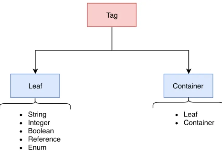
The IM may be seen as a tree composed of a group of elements. The elements of each descriptor have two different designations: leaf or container.
A leaf element is a single piece of information that defines a value in the context of the descriptor. The value datatype may be a string, integer, boolean, reference, or enum. On another hand, a container is a component that defines another level in the tree; therefore, it does not have any datatype associated.
In the end, in order to facilitate, all the different elements are called tags. Figure 2.8 portrays the differences between the elements designations.
Since the OSM IM covers many configurations, presenting the full trees would be very extensive. Thus, only the first level of elements is shown.
The first tree level of the VNFD is provided on figure 2.9.
The sub-elements are displayed in bold. In this case, apart from the sub-elements, the rest are only leafs since there are no reference elements.
Tag Leaf Container String Integer Boolean Reference Enum Leaf Container
Figure 2.8: Difference between the elements designations in OSM IM.
vnfd-catalog/ schema-version vnfd/ id name short-name vendor logo description version operational-status service-function-chain service-function-type vnf-configuration/ mgmt-interface/ internal-vld/ ip-profiles/ connection-point/ vdu/ vdu-dependency/ http-endpoint/ scaling-group-descriptor/ monitoring-param/ placement-groups/
Figure 2.9: VNFD structure tree.
In terms of leafs, only the operational-status, function-chain, and service-function-type do not represent metadata of the VNF. The operational-status, as the name suggests, refers to the operational status of the VNF (init, running, upgrading, terminate, terminated, failed). The service-function-chain and service-function-type are both related to Service Function Chaining (SFC), with the former being the type of
node in the SFC architecture and the latter being the type of service function. The ID, schema-version, name, short-name, vendor, logo, description, and version are all metadata elements that are used to give the package a unique identity. Regarding the sub-elements in this first level, they define most of the configurations that are possible to apply to a VNF.
Table 2.1 discriminates the utility of each sub-element presented on the first level of the VNFD tree by describing each one of them.
Sub-element Description
vnf-configuration/ Tag that provides the elements for configuring the
VNF. It allows to define if the VNF is configured via a script or a JuJu charm. If the choice is the latter then the primitives have also to be specified. More information regarding JuJu Charms is provided in section 2.6.4.
connection-point Contains the list of the VNF external
connection-points.
mgmt-interface/ Interface over which the VNFM manages the VNF.
vdu Sub-element on which the configurations of the
Virtual Deployment Units (VDUs) that compose the VNF are provided.
vdu-dependency Informs the orchestrator on which order the configured
VDUs should start.
internal-vld/ Provides information regarding the network topology
between the VNF internal components such as the VDU.
ip-profiles List of ip-profiles that describe ip characteristics for
a VLs.
placement-groups Catalog of placement-groups at VNF level. Describe
the strategy for the placement of computer resources in a cloud environment, therefore, the VDUs that are within the placemenht-group have to be specified.
scaling-group-descriptor Defines a group and ratio of VDUs in the VNF that
are used as a target for scalling actions.
monitoring-param Contains monitorable VDU or VNF parameters.
Continues on next page
Sub-element Description
http-endpoint The http-endpoint contains a group of endpoints to
be used by the monitoring-params.
Table 2.1: VNF possible configurations overview.
Further details on the elements of the VNFD descriptor are present on [30] and [18]. A VNFD example is presented on code block 1.
vnfd:vnfd-catalog: vnfd: - id: hackfest_basic-vnf name: hackfest_basic-vnf short-name: hackfest_basic-vnf version: '1.0'
description: A basic VNF descriptor w/ one VDU logo: osm.png connection-point: - name: vnf-cp0 type: VPORT vdu: - id: hackfest_basic-VM name: hackfest_basic-VM image: ubuntu1604 alternative-images: - vim-type: aws image: ubuntu-artful-17.10-amd64-server-20180509 count: '1' vm-flavor: vcpu-count: '1' memory-mb: '1024' storage-gb: '10' interface: - name: vdu-eth0 type: EXTERNAL virtual-interface: type: PARAVIRT external-connection-point-ref: vnf-cp0 mgmt-interface: cp: vnf-cp0
Code block 1: Hackfest Basic VNFD [31].
This example, provided on the 6th OSM hackfest, describes a VNF with one VDU.
This VNFD starts with a description and definition of basic configurations like the name, ID, description among others. Then, a connection-point named vnf-cp0 of the type VPORT is described.
The VDU defines, in the field count, that one VM based on the image ubuntu1604, should be instantiated. The VM should have only one VCPU with 1024MB of memory
and 10GB of storage. This VDU should have one external interface named vdu-eth0. This interface will be the point of connection between the VNF capsule and the VM. That link is described in the external-connection-point-ref field, which has the VNF connection-point associated. As there is only one VDU, there is no need to specify an internal interface. The management interface is a connection-point and, therefore, the vnf-cp0.
This VNF does not handle any cloud-init file nor any JuJu charm. Hence, no service primitive is configured. An example using primitives is shown in section 2.6.4.
Figure 2.10 displays a graphical representation of the VNFD described.
Name: hackfest_basic-vm Image: ubuntu1604 VM Flavor: - 1 VCPU - 1GB RAM - 10GB storage VNF: hackfest_basic-vnf VDU Interface: vdu-eth0 External-connection-point: vnf-cp0
Figure 2.10: Hackfest basic VNF diagram.
As previously stated for the VNFD, in the NSD tree presented on figure 2.11, the sub-elements are displayed in bold. Besides that, the leafs are all metadata. Some sub-elements are common to both of the descriptors, such as the connection-point, scaling-group-descriptor, ip-profiles, placement-groups, and the monitoring-param. The differences in specifications from the VNF and the NS in these elements are minimal. They mostly differ because the VNFs operate with the VDUs and the NSs work directly with the VNFs. Thus, in, for example, the monitoring-param, instead of monitoring the VDU, the NSD refers to monitoring VNFs. Another example is the sub-element vnf-dependency, which has the same role as the vdu-dependency. However, the dependencies should be VNFs from the constituent-vnfds and not, again, VDUs. Due to these reasons, for the NSD, the description of these sub-elements will not be provided. Table 2.2.2 provides the description of the elements that are unique to the NSD.
nsd-catalog/ schema-version nsd/ id name short-name vendor logo description version connection-point/ scaling-group-descriptor/ vnffgd/ ip-profiles/ initial-service-primitive/ terminate-service-primitive/ input-parameter-xpath/ parameter-pool/ key-pair/ user/ vld/ constituent-vnfd/ placement-groups/ vnf-dependency/ monitoring-param/ service-primitive/
Figure 2.11: NSD structure tree.
Sub-element Description
vnffgd/ Graph specified by a network service provider that
connects network function nodes in a bi-directional way where at least one node is a VNF through which the traffic is directed.
user/ The user is composed of the name and key pair of the
person using the NS.
key-pair/ List of public keys to be injected on the NS. constituent-vnfd/ List of the VNFs that form the NS.
Sub-element Description
initial/terminate-service-primitive/
The initial and terminate service primitive have the same configuration. Both of them deal with the def-inition of primitives to be executed on the NS level. The difference is that the initial service primitive ex-ecutes the primitives on the initialization of the NS and the terminate service primitive executes on the termination of the NS.
parameter-pool/ Specifies a range of values to use during the
configu-ration of NS.
input-parameter-xpath/ Sub-element which handles a list of XPaths9 that
point to parameters inside the NSD that can be cus-tomized during instantiation.
vld/ Deployment model that describes the connection
re-quirements between the VNFs and the NS endpoints. This sub-element resembles the internal-vld element from the VNF in terms of configurations.
service-primitive/ The service primitive works similarly to the
initial/terminate-service-primitive; however, this one is not associated with any time frame on the lifecycle of the NS. The primitive is expected to be executed whenever necessary as it is available on service-level for the NS.
Table 2.2: NS possible configurations overview.
Further details on the elements of the NSD descriptor are present on [32] and [18]. A NSD example using the VNF presented on codeblock 1 is provided on code block 2.
This NSD, which was bundled with the previous VNF on the 6th OSM hackfest, provides the description of a simple NS using one VNF and a single VL.
Firstly, all the metadata is set. Then, the constituent-vnfd is specified. Since this NS only holds one VNF, only one vnfd-id-ref is filled and it contains the ID of the VNF previously specified: hackfest_basic-vnf.
Lastly, the Virtual Link Descriptor (VLD) is created. It is named mgmtnet, is a management network and it describes which connection-points should be inter-connected. Given the constituent-vnfd, the hackfest_basic-vnf ’s connection-point
9https://www.w3.org/TR/1999/REC-xpath-19991116/
nsd:nsd-catalog: nsd:
- id: hackfest_basic-ns name: hackfest_basic-ns short-name: hackfest_basic-ns
description: Simple NS with a single VNF and a single VL version: '1.0' logo: osm.png constituent-vnfd: - vnfd-id-ref: hackfest_basic-vnf member-vnf-index: '1' vld: - id: mgmtnet name: mgmtnet short-name: mgmtnet type: ELAN mgmt-network: 'true' vnfd-connection-point-ref: - vnfd-id-ref: hackfest_basic-vnf member-vnf-index-ref: '1' vnfd-connection-point-ref: vnf-cp0
Code block 2: Hackfest Basic NS [33].
should be connected to this VLD.Figure 3.1 displays the connections between the VNF and the NS’s VLD. Name: hackfest_basic-vm Image: ubuntu1604 VM Flavor: - 1 VCPU - 1GB RAM - 10GB storage VNF: hackfest_basic-vnf VDU Interface: vdu-eth0 External-connection-point: vnf-cp0 VL: mgmtnet NS: hackfest_basic-ns
Figure 2.12: Hackfest basic NS diagram.
2.6.4 JuJu Charms
Juju is an open-source modeling platform for cloud software service. It allows its users to quickly and efficiently deploy, configure, manage, maintain, and scale cloud applications [34].
There are three main concepts in charms: actions, hooks, and layers. Actions are the programs that the user needs to be executed, hooks are signals that may or may not occur, and layers are an aggregation of actions and hooks.
Charms are built in layers, which means that a charm is a collection of actions and hooks. In addition to those, a layer may import other layers resulting in a new set of functionalities. This approach is right because it allows charms to be reusable and easily modifiable.
Given the layered architecture, when developing a new charm, what is being created is a new layer.
Figure 2.13 and 2.14 present two distinct tree directories. The former presents the structure of a new layer, and the latter presents the final charm after being built, this is, combining the imported layers and the newly created. Starting by figure 2.13, five main files need to be configured: metadata.yaml, actions.yaml, layer.yaml, reactive/action.py, and actions/action.
The metadata.yaml includes all the high-level information of the charm, such as the creator name, description, among others. The layer.yaml file states all the layers on which the new layer is based. Two layers are mandatory when developing a new charm in the OSM context: the basic and the VNF proxy layer. The former is required for all the charms because it contains the necessary configuration for making a charm work. The latter is necessary to set configurations to make the charm a proxy charm. In the OSM context, proxy charms are used because they are the bridge of communication between the OSM infrastructure and the deployed VMs. The actions.yaml contain the high-level description of the actions implemented on the charm. However, to perform the actions, there are two extra steps: the actions folder has to be created, and for each necessary action, a new script, which has to be an executable file, has to be added to that folder. In the tree, the script is presented as actions/action, and it is the connection point between the signal to perform the action and the reactive platform. Therefore, a Python10 script containing the actual implementation of the action must be created
and stored on the reactive folder. The reactive programming pattern allows the charm to respond to changes in state, including lifecycle events, in an asynchronous way [35], [36]. In the tree, this is mapped as reactive/action.py
After these steps, the charm has to be built. In this process, the configurations of the layers described in the layer.yaml and the code of the new layer are joined and form the brand new charm, which will be ready to use. The final tree after this process is presented on figure 2.14.
10https://www.python.org/
$JUJU_REPOSITORY/layers/ <charm name>/ README config.yaml icon.svg layer.yaml metadata.yaml actions.yaml actions/ action reactive/ action.py tests/
Figure 2.13: Charm new layer structure.
$JUJU_REPOSITORY/builds/<charm name>/ requirements.txt README icon.svg copyright tox.ini config.yaml actions.yaml Makefile actions/ action reactive/ action.py deps/ bin/ hooks/ tests/
Figure 2.14: Charm new layer after building.
Having charms by themselves does not add anything to OSM. They are only useful if there is a way of mapping the charms actions to the descriptors. As described in section 2.6.1, the VNFD holds a set of operations to define primitives. The definition of these primitives provides the necessary connection between the descriptors and the charms since they are responsible for calling the actions to be run on the VNF. The role of these primitives in the OSM ecosystem is described in section 2.6.5.
2.6.5 Open Source Mano architecture
Looking at figure 2.15, the modules that compose OSM’s architecture are easily identified: the OSM client as well as the lightweight User Interface (UI), the Northbound Interface (NBI), the Lifecycle Manager (LCM), the VNF Configuration and Abstraction (VCA),
the Resource Orchestrator (RO), the Policy Manager (POL) and the Monitoring Module (MON) components. There are also common databases. The communication between these modules occurs via a Kafka11 bus. One multi present component is the
OSM IM.
According to figure 2.15, the OSM access point to the users occurs via the OSM client or the lightweight UI. As it was stated before, OSM was envisioned as a simple system. Therefore, having a transparent interaction with the users is mandatory.
Lightweight UI and the OSM client were developed to provide a fluid user experience by offering straightforward management of the VNFs’ and NSs’ lifecycle. It also provides
real-time data of the virtualized services and functions as well as a full description of network topologies. The communication between this module and the other OSM components takes place via the Northbound Representational State Transfer (REST) API (NBI). The OSM client, is a Command Line Interface (CLI) tool that replicates most of the functionalities of the lightweight UI.
OSM’s NBI, which is based on NFV SOL005 [37], is the hidden access point between the user and OSM’s functionalities.
Figure 2.15: OSM architecture [38].
Having now the context of the VNF and NS packages and given the architecture presented in figure 2.15, the interaction between these components and modules can now be described. Figure 2.16 presents a high-level overview of the operations on the OSM environment.
Considering the information contained in the VNF and NS packages, their content can be split into two groups: in the case of the VNFs there are the resource descriptions and the management procedures. On another hand, the NS packages have information about topology and management procedures, as well.
When a new NS is onboarded into OSM, the resource descriptions and the topology information go through the NBI to the RO.
The RO module orchestrates the resources available for the OSM environment. It manages and controls the allocation of resources through multiple geo-distributed VIMs and multiple Software-Defined Networks (SDNs) controllers. Therefore, the RO deploys the necessary VMs in order to match the resources and topology manifested in the descriptors using the VIM connectors. In figure 2.16, the purple lines illustrate the described workflow.
The other group of content, the management procedures, are also driven by the 26
Figure 2.16: Interaction between OSM modules over the deployment of NSs and VNFs [29].
NBI. Nevertheless, they follow a different path since this content is forwarded to the VCA. The VCA works as a VNFM. Consequently, it is the component responsible for enabling configurations to/from the VNF. When allied with JuJu, this module is in charge of signalizing the VNF to perform a specific action. The actions are encapsulated in charms. The blue lines highlight this workflow in figure 2.16.
In conventional networks, day zero involves the configuration of all the physical equipment; this is, connecting all the cables and ensuring connectivity between them. Day 1 is related to making the network ready to work. To do this, the Operational Support System (OSS) extends to all hardware its configurations, including the final network and its neighbors. Licenses injection is also performed at this stage. Finally, day 2 includes all the configurations to keep day-to-day operations running.
When it comes to NFV, the significant differences between the traditional network configurations happen on day zero and day one configurations. However, day two is the same for both approaches. As there is no need for specific hardware configuration in NFV the NSs and VNFs deployments are handled by the orchestrator (MANO component in NFV). Due to this reason, and since the configuration of the components is done basically at the same time as the deployment, day zero and day one co-occur. As OSM implements the ETSI MANO specifications, the same path is followed on its lifecycle.
is instantiated and the request arrives to the RO, this module starts the process of deploying VNFs. To do so, the RO contacts the VIM to request the necessary VMs with the requirements specified on the VNFD. With the VMs deployment, the cloud-init file present on the VNF package is injected and its configuration takes place. These configurations are not related to the VNF itself but only to the configuration of the Virtual Machine.
Happening basically at the same time, when the RO completes the deployment of the VMs, day one configuration takes place. The initial-config-primitive is run for each VNF, and the charm actions that are associated with this primitive are executed.
Regarding day two configuration, the primitives that can be executed are the config-primitive or the service-config-primitive. If the NBI receives a request for a NS config-primitive, then the sequence of charm actions associated with the service-primitive are executed. On another hand, if the request is for a VNF primitive, then the config-primitive is triggered, and its sequence of charm actions is run. The request may also be about a scaling operation. A scaling operation may require the deployment of new VMs. If that is the case, the RO needs to take care of that deployment, and the additional configuration should be provided. Apart from that, the primitive process is the same as before. However, the primitive triggered is the pre/post-scaling-primitive, which executes the sequence of charm actions described in the VNFD.
2.7 5GinFIRE
5GinFIRE is a project that started in 2017, and it is expected to end in 2019, funded by the European Horizon 2020 Programme, which aims to build an extensible 5G-NFV based ecosystem focused mainly on vertical industries. This project is identified as a "forerunner experimental playground" since it intends to be the platform where new components, architectures, or APIs are tried before being deployed into production [9]. The described motivation relies on two principles: (i) being driven by ETSI standards and open source code and (ii) focusing on automotive and smart cities verticals [39]. The former principle is crucial since it is one of the aspects on which 5GinFIRE stands out, given that it is the first platform to have leading standardization practices at its core [9].
Figure 2.17 presents the 5GinFIRE architecture. Although the overall concept is, as previously stated, aligned with the ETSI NFV architecture, the project aims to extend it, so it becomes suitable for every vertical’s requirements and specifications [9].
From figure 2.17, is is possible to identify four main architectural blocks: (i) the Experimental Instances of Verticalss (EVIs), (ii) the 5GinFIRE Network Virtualized
Infrastructures (NVIs), (iii) the automated MANO, and (iv) the 5GinFIRE design and architecture framework.
Figure 2.17: 5GinFIRE architecture [8].
The EVIs is the agglomeration of the multiple virtual functions from each vertical [9].
The 5GinFIRE NVI is comprised of the NFVI, which, as previously described in section 2.2.3, offers the resources for the VNFs execution by providing the virtualization layer to abstract the physical hardware from the VNFs. This block also holds the VIMs, which are responsible for the management of the infrastructures’ operation. 5GinFIRE is a geographically distributed multi-VIM environment. This approach raises resources placement challenges for each EVI. This issue is addressed by the automated MANO, which, for this project, is OSM. Therefore, the auto-MANO block is responsible for the orchestration and lifecycle management [9].
Last but not least, the 5GinFIRE design and architecture framework contains all the APIs and platforms to provide facilities for experiences and integration of new services [9].
There are multiple designations for each user on the scope of the project. In order to understand each user’s interaction and role within the project, the definition of each stakeholder is described in table 2.3.
Actor Description
Experimenter User that takes advantage of the 5GinFIRE
environ-ment to deploy an experienviron-ment.
VNF Developer User responsible for uploading the VNF and NS on
the 5GinFIRE portal.
Testbed Provider User that provides the testbed and is responsible for
its administration, configuration, integration, among others.
Experimenter Mentor User responsible for keeping track of the experiences
status and resource usage.
Services Administrator User that mantains the 5GinFIRE infrastructure.
Table 2.3: Possible roles on the 5GinFIRE environment [9], [40].
Figure 2.18 shows the different collaborators of 5GinFIRE and their role in the project. University Carlos III of Madrid provides the centralized OSM deployment that orchestrates all the testbeds. The testbeds give different test platforms for different verticals applications such as automotive, media, health, among others, geo-distributed in many different locations. Finally, the 5GinFIRE portal, developed and supported by the University of Patras, offers the connection point between the experimenters and VNF developers and the OSM and testbeds.
Figure 2.18: 5GinFIRE colaborators and their purposes (adapted from [41]).
The experimentation workflow incorporates each one of the actors and components. Firstly, the VNF developers construct the experiment VNF by providing an OSM compliant VNFD and uploading it into the 5GinFIRE portal. The experimenters are then able to develop the NS with the submitted VNF. Once finished, they can select the testbed in which they want to deploy the experiment and define some other details such as metadata or scheduling. The experiment is then submitted to approval. The experimenter mentor is responsible for taking care of the submitted experiment and has to ensure that the testbed owners and the experimenters are on the same page regarding scheduling, amount of resources, among others. At this point, it is also necessary to ensure that the VNFs utilized by the NS can be deployed. As a consequence, the service administrator has to validate the VNF manually to ensure that the package is ready to be on-boarded. When everything is set, the mentor approves the experiment submission, and the onboarding occurs.
On this workflow, one critical step is the manual validation of the VNFs since it consumes much time, and it is not scalable. Therefore, the need for an automated process arises [10]. This Dissertation aims to provide an automated solution for this step and integrate it on the 5GinFIRE design and architecture framework.
Once the package is validated, the experiment starts. The centralized OSM receives the request to deploy the NS utilizing its constituent VNFs and which VIM (testbed) should utilize resources from. Then, it proceeds to instantiate the necessary VMs, and the required configurations are applied. Once everything is set, the experiment is ready to operate, and the process is completed.
2.8 DevOps
Market requirements are not a problem just for networks. Software also suffers from constant customers’ demands since users expect fast delivery of their unceasing new features. Frequent releases are not only essential for fulfilling such requisites but also to create an advantage in the market [42]. Although the usage of Agile [43] methodology brought optimization related to software development, operation tasks are not included in these procedures [44], since the goals of each sector are misaligned: the development teams aim for change whether the operations teams strive for stability [45].
DevOps, which was firstly introduced in 2009 by Patrick Debois, acknowledges the need to incorporate software development and operational deployment [46] continually. Derived by the combination of Development (Dev) and Operations (Ops) [47]–[50], it composes a paradigm that enables the collaboration between developers and operation teams, resulting in more efficient teamwork [49]–[51]. By providing such interconnection, DevOps extends Agile [44], [47], [52].
There are four key enablers of DevOps: culture, automation, measurement, and sharing. Regarding culture, both operations and development teams must make an effort to participate in each other’s tasks in order to be aware of what is happening at each end. Build, deployment, and testing automation allows faster feedback contributing to the referred gain of efficiency. Measurement embraces the monitoring by collecting metrics not only from the deployment itself but also from the developers. Furthermore, collecting system logs should be another collaborative measurement task between both teams. Finally, sharing is about spreading knowledge, specifically by providing information about development tools or, on another hand, techniques for managing the infrastructure [53].
The main goals of DevOps are to continuously deliver high-quality services while emphasizing simplicity and agility as well as blend the development and operations tasks by encouraging collaboration and trust [52].
DevOps main components are pictured on figure 2.19, which is based on [54]. On the referred image, it is possible to acknowledge four stages within DevOps: CI, Continuous Testing (CT), Continuous Monitoring (CM), and Continuous Delivery (CD).
Plan Code Build Test Release Deploy Operate
Devops Continuous Integration Continuous Testing Continuous Monitoring Dev Ops Continuous Delivery
Figure 2.19: DevOps different components.
Continuous Testing is the component in which tests are configured to run automati-cally as soon as the code is committed to the repository. This approach reduces the time between the introductions of errors and their detections. Continuous Monitoring provides the monitoring of the hardware and software after deployment. Continuous Delivery is the methodology of continuously ensuring that the software is ready to be deployed in the production environment. Lastly, Continuous Integration is an automat-ically triggered process that provides code testing and validation and its subsequent packaging in order to be deployed later. There should be multiple code submissions for CI during the day, and failure details should also be provided [54], [55].
The work described in this Document is inserted on the DevOps approach, most precisely on the CI step. Thus, the next subsection, 2.8.1, provides a more detailed
![Figure 2.1: Transition to NFV[11].](https://thumb-eu.123doks.com/thumbv2/123dok_br/15722272.1070612/32.892.116.760.127.892/figure-transition-to-nfv.webp)
![Figure 2.2: ETSI NFV architectural reference[16].](https://thumb-eu.123doks.com/thumbv2/123dok_br/15722272.1070612/33.892.133.791.131.577/figure-etsi-nfv-architectural-reference.webp)
![Figure 2.5: Comparison between ETSI NFV MANO architectural specification [16] (left) and OSM (right) [28].](https://thumb-eu.123doks.com/thumbv2/123dok_br/15722272.1070612/38.892.110.766.187.556/figure-comparison-etsi-nfv-mano-architectural-specification-right.webp)
![Figure 2.15: OSM architecture [38].](https://thumb-eu.123doks.com/thumbv2/123dok_br/15722272.1070612/50.892.115.752.331.649/figure-osm-architecture.webp)
![Figure 2.16: Interaction between OSM modules over the deployment of NSs and VNFs [29].](https://thumb-eu.123doks.com/thumbv2/123dok_br/15722272.1070612/51.892.126.776.132.547/figure-interaction-osm-modules-deployment-nss-vnfs.webp)
![Figure 2.17: 5GinFIRE architecture [8].](https://thumb-eu.123doks.com/thumbv2/123dok_br/15722272.1070612/53.892.134.784.183.682/figure-ginfire-architecture.webp)
![Table 2.3: Possible roles on the 5GinFIRE environment [9], [40].](https://thumb-eu.123doks.com/thumbv2/123dok_br/15722272.1070612/54.892.135.743.753.1080/table-possible-roles-the-ginfire-environment.webp)