1 10º CONGRESSO NACIONAL DE SISMOLOGIA E ENGENHARIA SÍSMICA
DETERMINATION OF THE CRITICAL ANGLE OF SEISMIC INCIDENCE IN
STANDARDISED PROCEDURES FOR THE SEISMIC SAFETY
ASSESSMENT OF 3D RC BUILDINGS
DESPOINA SKOULIDOU PhD student F.E.U.P. Porto-Portugal XAVIER ROMÃO Assistant Professor F.E.U.P. Porto-Portugal ABSTRACTThis study proposes an analytical expression for the straightforward determination of the angle of seismic incidence that leads to the maximum structural demand of reinforced concrete buildings when subjected to Lateral Force Analysis. The demand parameter under consideration is the maximum total displacement of single storey and isotropic multi-storey buildings, while the maximum interstorey drift may also be employed. The proposed expression is defined based on the geometrical and mechanical characteristics of the structure. The characteristics of the seismic loading represented by the elastic response spectrum are also integrated into the formulation of the expression.
KEYWORDS: Critical angle of incidence, three-dimensional analysis, lateral force analysis, RC buildings.
Determination of the critical angle of seismic incidence in standardized procedures for the seismic safety assessment of 3D RC buildings
2
1. INTRODUCTION
Earthquake-related standards allow the use of procedures based on lateral forces for the seismic analysis of buildings in which the influence of higher modes of vibration can be neglected. In Eurocode 8 part 3 (EC8-3) [1], which is the part of the Eurocode suite of documents that prescribes seismic safety assessment procedures for existing structures, an additional requirement is enforced for the applicability of the Lateral Force Analysis (LFA). This requirement aims to quantitatively evaluate the regularity of the structure by checking the uniformity of the distribution of deformations across the structure under earthquake loading. When all requirements are fulfilled and LFA is carried out, the time-dependent earthquake action is represented by time-invariant horizontal static forces. It is usually accepted that a safe estimation of the maximum demand will be achieved if the seismic forces are applied along the building’s structural axes independently and by combining these action effects using an appropriate combination rule [2], [3]. However, it has been proven that this approach may lead to unconservative results. Therefore, the consideration of different orientations of the seismic action should not be disregarded [4]-[6]. Nevertheless, the determination of the seismic orientation that leads to the highest demand, which will be referred hereon as the critical angle of seismic incidence (ASIcrit), is a complex issue that is still unsolved.
Existing literature that addresses the ASIcrit within the context of LFA is limited and
mainly orientated towards the design of new structures. Morfidis et al. [7] examined the effect of the angle of seismic incidence (ASI) with respect to the required column reinforcement in the context of the Greek seismic code (ΕΑΚ) [8]. The authors addressed reinforced concrete (RC) buildings with various configurations in plan and found that the reinforcement may be substantially underestimated if the ASIcrit is not
taken into account. Since the calculation of the reinforcement requires the combination of different action effects (axial force and bending moments in two perpendicular directions), EAK defines two different combination approaches [8]. Similar trends were observed by Quadri and Madhurin [9] that analysed a symmetric multi-storey RC building with a square plan and examined the action effects in columns. In this study, the different action effects were not combined as in the study of Morfidis et al. [7]; instead each action effect (axial forces, shear forces and bending moments) was considered separately. Both studies concluded that there was no unique ASI that maximizes the demand for all parameters simultaneously and that neglecting the ASIcrit,
i.e. applying the lateral forces only along the structural axes, may lead to unconservative results. However, no constant trends were reported on how to take the ASIcrit into consideration in a robust way and in accordance with the code-oriented
semi-probabilistic approach.
In light of this, a methodology is proposed for the determination of the ASIcrit in the
context of LFA. The methodology is defined in the context of the seismic safety assessment of existing RC buildings and establishes critical demand criteria for single storey buildings and for a special category of multi-storey buildings based on the maximum total displacement. The same methodology can also be implemented for the determination of the ASIcrit that leads to maximum interstorey drifts. Within the current
methodology, an analytical expression is established for the determination of the ASIcrit
based only on the geometrical and material characteristics of the building. The proposed expression is able to be updated in order to account for the shape of the response spectrum and to be applied in buildings that require different values of the lateral forces depending on the horizontal direction under consideration. Finally, two case studies are presented for the validation of the proposed methodology. A single storey building and an isotropic multi-storey building, both not symmetric in plan, subjected to a parametric analysis for different ASIs varying from 0o to 360o in steps of
1o. The results are then compared with the results predicted from the analytical
Determination of the critical angle of seismic incidence in standardized procedures for the seismic safety assessment of 3D RC buildings
3
2. REVIEW OF CONCEPTS OF THE STATIC BEHAVIOUR OF BUILDINGS
2.1. Single storey buildings
The methodology developed for the determination of the ASIcrit is based on the static
behaviour of three-dimensional (3D) single storey buildings non-symmetric in plan, as described in [10]. Some basic concepts of single storey structures and of their behaviour under static loading are presented in advance to provide some background for the developed rationale. The mechanical behaviour of the materials are considered to be linear elastic and the floors are considered to be in-plane rigid and out-of-plane flexible. Furthermore, the vertical elements are considered to be axially rigid. Single storey buildings with the aforementioned properties always possess an elastic centre CS and principal axes (I, II, III), where CS is the intersection of the vertical principal axis
III (also termed elastic axis) with the floor diaphragm [10], [11].
For a single storey building with the aforementioned properties, the horizontal stiffness can be described by a 3×3 matrix with respect to an arbitrary reference system O (X,Y,Z), where X-Y is the horizontal plane, Z is the vertical axis and O is their intersection point. For an arbitrary horizontal loading vector [FX, FY, MZ] T, the following
static equilibrium has to be satisfied:
⋅ = θ XX XY XZ X X YX YY YZ Y Y ZX ZY ZZ Z Z K K K u F K K K u F K K K M (1)
where Kij are the stiffness matrix coefficients and [uX uYθΖ] T is the displacement vector
with respect to the O (X,Y,Z) reference system.
Based on the properties of CS [10], [11], it is always possible to define a special
reference system CS (I, II, III) with respect to which the stiffness matrix takes a diagonal
form. This reference system is the principal system of the structure and is defined by a horizontal plane I-II (rotated by an angle ω with respect to the X-Y plane), the vertical axis III and their intersection point CS. In the principal reference system, the static
equilibrium is decomposed into three independent equations:
, ,
I I I II II II III Cs Cs
K u F K u⋅ = ⋅ =F K ⋅
θ
=M (2)where KI, KII, KIII are the principal stiffness matrix coefficients and [uI uIIθCs] T and [FI FII
MCs] T are the displacement and the loading vectors, respectively, with respect to CS (I,
II, III).
The importance of the presented transformation lies in the fact that the translational principal stiffnesses KI and KII correspond to the minimum and maximum stiffness of
the system, respectively. Consequently, the principal periods TI and TII correspond to
the maximum and minimum periods of the system, respectively. It has been proven [12] that the flexibility coefficients (fi = 1/Ki) for each uncoupled fundamental direction of
the structure lie on an ellipse with a semi major axis a = fΙ and a semi minor axis b = fII.
Similarly, it can be proven that the uncoupled fundamental periods given by:
, 2
unc i i
T = ⋅ ⋅
π
m f⋅ (3)also lie on an ellipse with a semi major axis a = TΙ and a semi minor axis b = TII and
can be expressed by:
( )
( )
2 2 2 2 2 2 ( ') cos ' sin ' II unc II I I T T T T T ⋅ = ⋅ + ⋅α
α
α
(4)Determination of the critical angle of seismic incidence in standardized procedures for the seismic safety assessment of 3D RC buildings
4 as a function of the angle α’, which is the angle of the respective direction under consideration with respect to principal axis I. The importance of this concept is shown in the following.
2.2. Multi-storey buildings
General multi-storey buildings do not have an elastic axis or principal bending directions [12], [13], therefore the diagonalization of the stiffness matrix and the decomposition of the static equations presented in Section 2.1. are not able to be fully implemented. Nevertheless, there are special categories of multi-storey buildings for which those concepts are still usable. Buildings for which an elastic axis and principal bending planes can be defined belong to one of the following categories of systems [12]-[14]: systems with two horizontal axes of symmetry in plan view, isotropic systems, ortho-isotropic systems and complex-isotropic (coaxial) systems.
All the previously mentioned systems have principal bending planes (I-III, II-III) the intersection of which defines the elastic axis III of the system. Furthermore, the elastic axis of multi-storey buildings possesses elastic properties similar to those of the elastic axis of single storey buildings, as summarized by [11]. Given these properties, the static response of the system is obtained by the superposition of two states of pure bending within the planes (I-III, II-III) and of one state of pure torsion about the axis III. Generally, any N-storey building satisfies the following static equilibrium with respect to an arbitrary reference system (X,Y,Z) [15]:
xx xy xz x x yx yy yz y y zx zy zz z z K K K u f K K K u f K K K m ⋅ =
θ
(5)where u̲x, u̲y, θ̲z are the N-dimensional vectors of translations uxi, uyi and rotations θzi
with respect to the Xi, Yi, Zi axes, respectively, with i = 1 to N. Furthermore, f̲x, f̲y, m̲z are
the N-dimensional vectors of forces Fxi, Fyi and moments Mzi with respect to the Xi, Yi,
Ziaxes, respectively, with i = 1 to N. Finally, each K̲ij element is a N × N stiffness matrix
with i, j given by all the combinations of x, y and z. In isotropic buildings, the horizontal stiffness matrices K̲n of all elements have the following form [15]:
0, 1,2..
n k Kn n
Κ = ⋅ = (6)
where kn is a numerical coefficient and K̲0 is a constant reference matrix of order N
(e.g. the stiffness matrix of an element of the system). Furthermore, it has been proven that matrices K̲ij in Eq. (5) have the following form [15]:
0, , , ,
ij k Kij i j x y z
Κ = ⋅ = (7)
where the coefficients kij = kji are calculated as functions of kn. The static equilibrium in
Eq. (5) of the N-storey building with respect to the global reference system (X,Y,Z) may then be re-written as presented in Eq. (8) after replacing Eqs. (6) and (7) in Eq. (5).
xx O xy O xz O x x yx O yy O yz O y y zx O zy O zz O z z k K k K k K u f k K k K k K u f k K k K k K m ⋅ =
θ
(8)Determination of the critical angle of seismic incidence in standardized procedures for the seismic safety assessment of 3D RC buildings
5 0 0 0 0 0 0 I O I I II O II II III O k k k K u f k K u f k K m ⋅ =
θ
(9)where kI, kII, kIII are calculated as defined as in Section 2.1. by replacing Kij of Eq. (1)
with kij of Eq. (8). The terms f̲I, f̲II and m̲K are the N-dimensional vectors of the loads and
u̲Ι, u̲ΙΙ and θ̲k are the N-dimensional vectors of displacements with respect to the
principal reference system (I, II, III). The coordinates of the location of the elastic axis and the orientation angle ω of the horizontal principal axes (I, II) are then determined from the conditions kII,III = 0, kI,III = 0 and kI,II = 0, respectively. A similar procedure may
be followed for the definition of the principal stiffness matrix in ortho-isotropic and complex-isotropic systems as described in the study of [15]. Finally, the uncoupled fundamental periods can be expressed by Eq. (4).
3. DETERMINATION OF THE CRITICAL ANGLE
3.1. Presentation of the methodology
3.1.1. Characteristics of the structure
The solution presented next is derived for single storey structures, yet the same expressions can be used for the case of multi-storey buildings that possess an elastic axis. Following the procedure described in Section 2., the CS and the principal axes (I,
II, III) are determined. Based on the properties of CS [10], [12], a static force passing
through the centre of stiffness will cause a translation without rotation of the floor diaphragm. During the rotation of a unit static force around CS, the peak displacement
vector defines an ellipse with axes I, II and lengths of the semi-axes equal to fΙ (= 1/KI)
and fΙΙ (= 1/KII), respectively. In addition, a unit torsional moment about a vertical axis
causes rotation of the diaphragm about Cs. Therefore, a horizontal static force F
rotating about any point of the diaphragm, e.g. point O in Figure 1, will cause an elliptic translation of Cs and a rotation of the diaphragm around Cs. The overall displacement
of the floor can then be obtained as a superposition of two states of pure translation within the planes (I-III, II-III) and of one state of pure rotation about the axis III. This rationale is illustrated in Figure 1, where the coordinates of Cs (x'Cs, y'Cs) are
determined with respect to the reference system O (X,Y,Z) in the rotated system of axes and the coordinates of point A (x'Α, y'Α) are determined with respect to the principal coordinate system Cs (I, II, III). The value of the moment M that causes
rotation will depend on the perpendicular distance d between F and Cs.
y' Cs y' A x'A x'Cs X Y O F=1 I II CS d A f1 f2 M=1*d I II CS A O F
=
+
A I II O CS X Y X YFigure 1: Displacement of a single storey building subjected to a horizontal unit static force applied at O with an arbitrary direction α with respect to the structural axes X-Y.
Determination of the critical angle of seismic incidence in standardized procedures for the seismic safety assessment of 3D RC buildings
6 cos( ') sin( ') cos( ') ' - sin( ') ' CSX I CS Y II Z CS CS III F u F u y x F ⋅ Κ ⋅ = Κ ⋅ ⋅ ⋅ Κ α α θ α α (10)
The displacement of a generic point of the diaphragm, e.g. point A in Figure 1, may then be calculated according to Eq. (11) that defines the displacement of A as a function of the displacement of CS based on rigid body kinematics.
-A A Cs C Z X Y A Y Y A Z Z Z s u y u u u x ⋅ = + ⋅ θ θ θ θ (11)
The total resultant displacement of a generic point A can then be calculated using the Pythagorean Theorem:
(
) (
2)
2 ( ') ( ') ( ') A A A X Y u α = u α + u α = 2 2( cos( ') sin( ') ) ( cos( ') sin( ') )
cos( ') K K sin( ') K K A A I III II III F y F x F y F x F y F x K K ⋅ − ⋅ ⋅ − ⋅ ⋅ + ⋅ + ⋅ ⋅ − ⋅ ⋅ = Κ Κ α α α α α α 2 2
2 cos( ') (cos( ') K sin( ') K) sin( ') (cos( ') K sin( ') K)
A A I III II III y x y x F y x K K ⋅ − ⋅ ⋅ − ⋅ ⋅ − + + Κ Κ α α α α α α (12)
where the lateral force F is determined according to the standard for each uncoupled fundamental period according to the procedure presented in the next section.
3.1.2. Characteristics of the input seismic action
The response spectrum used for the representation of the seismic action in the context of the seismic safety assessment of EC8-3 corresponds to the elastic ground acceleration response spectrum provided by Eurocode 8 Part 1 (EC8-1) [16]. The shape of the spectrum is divided into four branches, the limits of which are determined by National Determined Parameters (NDP). The second branch corresponds to the constant spectral acceleration region, the third to the constant spectral velocity region and the fourth to the constant spectral displacement region.
The elastic response spectrum is defined as a function of the structural period. In LFA, the structural period corresponds to the fundamental period of vibration in the horizontal direction being considered. Section 2.2 showed that the uncoupled structural period can be expressed as a function of the angle α’, Tunc(α’). Accordingly, the spectral
acceleration Se can also be expressed as a function of the same angle, which will
coincide with the angle of seismic incidence. Finally, the resultant lateral force can be expressed by:
’ ) ( ’ · · ( e unc( ))
Determination of the critical angle of seismic incidence in standardized procedures for the seismic safety assessment of 3D RC buildings
7 where m is the total mass of the structure and λ is a modal mass correction factor used to account for the effective modal mass of the first (fundamental) mode of vibration. This effective first mode modal mass is on average 15% smaller than the total mass in buildings with at least 3 storeys and translational degrees of freedom in each horizontal direction.
3.2. Solution for constant lateral forces
In the special case for which both the principal fundamental periods TI, TII fall onto the
horizontal branch of the response spectrum, the spectral acceleration is independent of the uncoupled fundamental period. Therefore, the horizontal force is invariant for all ASIs. In that case, the ASIcrit that leads to the maximum displacement does not depend
on the value of the force, which is a constant Fconst, and Eq. (12) takes the following
form:
2 2
2 cos( ') (cos( ') - sin( ') ) sin( ') (cos( ') - sin( ') )
( ') - K K K K const A A I III II III y x y x u F y x K K K K Α = ⋅ + + ⋅ ⋅ ⋅ ⋅ α α α α α α α (14)
Based on this simplification, the ASIcrit can be calculated by deriving Eq. (14) with
respect to α’ and by equalizing the derivative to zero:
( ') 0 '
'
A critdu
d
= ⇒
α
α
α
(15)3.3. Solution for variable lateral forces
In cases other than those addressed in Section 3.2, the horizontal force is a function of the fundamental period. Therefore, Eq. (12) takes the following form:
2 2
2 cos( ') (cos( ') - sin( ') ) sin( ') (cos( ') - sin( ') )
( ') ( ') - K K K K A A I III II III y x y x u F y x K K K K Α = + + ⋅ ⋅ ⋅ ⋅ ⋅ α α α α α α α α (16)
When both TI and TII belong to the same branch of the spectrum, e.g. TII > TC and TI <
TD, Eq. (16) has only one branch and the critical angle is determined by deriving the
equation for every α’ = [0,360] and by equalizing the derivative to zero. When TI and TII
belong to different branches of the spectrum, Eq. (16) has more than one branch and each branch corresponds to a certain range of angles. The limits of the branches are determined from Eq. (4) by replacing the uncoupled period by the appropriate NDP: TB,
TC or/and TD.
4. EXAMPLES OF APPLICATION
4.1. Characteristics of the seismic action
In both case studies the seismic action is represented by the Type 1 elastic response spectrum defined by EC8-1. The parameters describing the spectrum correspond to a ground type B, a 5% viscous damping and a ground acceleration on type A ground with a value of 0.36g (S = 1.2, TB = 0.15 sec, TC = 0.5 sec, TD = 2.00 sec, η = 1). The factor
Determination of the critical angle of seismic incidence in standardized procedures for the seismic safety assessment of 3D RC buildings
8
4.2. Single storey building
The first case study comprises a non-symmetric single storey structure with a configuration that was chosen in order to represent a complex case study. The plan view as well as the material and the geometrical characteristics of the structure are presented in Figure 2. Assumptions regarding the mechanical behaviour of the materials described in Section 2. are valid as well. The local structural axes of columns C and D are rotated -45o about the vertical axis Z and all columns are considered fixed
to the ground.
Following the procedure described in Section 2. the lateral stiffness matrix of the structure was determined in the global coordinate system O (X,Y,Z). Subsequently, the coordinates of CS, xCs = 0.422 (m) and yCs = 0.999 (m), and the angle ω = -31.03o were
determined in the same coordinate system. Next, the principal stiffness matrix was computed. The coordinates of CS, x’K = -0.16 m and y’K = 1.07 m, with respect to O and
the rotated axes (Figure 2a) were determined as well as the coordinates of A, x’A =
-0.52 m and y’A = -3.82 m, with respect to the principal reference system CS (I, II, III).
The top of column A was selected as the reference since it corresponds to the point of the diaphragm with the maximum resultant displacement, thus the maximum demand.
y'Cs 4 m 4 m A O x x y x y x y II I CS y'A x'A y x'Cs Height 4.0 m E (modulus of elasticity) 25 GPa Column A 0.3 x 0.3 (b x h) (m2) Column B 0.3 x 0.6 (b x h) (m2) Column C 0.3 x 0.6 (b x h) (m2) Column D 0.3 x 0.6 (b x h) (m2) Beams 0.25 x 0.6 (b x h)(m2)
Figure 2: Plan view, material and geometric characteristics of the single storey building
Assuming a translational total mass m of 15 ton, the principal uncouple fundamental periods are determined by:
2 0.16sec, 2 0.11sec I I II II I II m m T T T T K K = ⋅ ⋅π → = = ⋅ ⋅π → = (17)
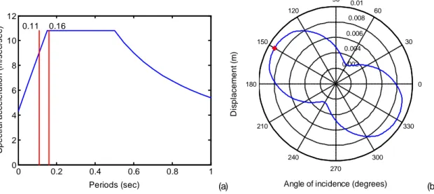
Figure 3a shows that the principal fundamental periods fall into different branches of the spectrum. Consequently, the expression of the maximum displacement of any point of the diaphragm will be given by Eq. (16) where F(α’) is defined by:
α α α α π α α α π α α π α Τ Τ Τ Τ ⋅ ⋅ ≤ ≤ = ⋅ ⋅ − ⋅ ≤ ∪ ≥ ⋅ ⋅ ≤ ∪ ≥ 2.5 , 0 ' ( ') 1 1.5 , ' - ' 2.5 , - ' ' B unc B B B B a S for T F a S for T a S for (18)
where Τunc is obtained by Eq. (4). The branches will be separated at the angle α’ΤΒ =
Determination of the critical angle of seismic incidence in standardized procedures for the seismic safety assessment of 3D RC buildings
9 For π ≤ α’ ≤ 2π, F(α’) will be symmetric. By inserting the coordinates of the points and the values of the principal stiffness matrix in Eq. (16), the resultant displacement of point A can be calculated for every value of α’. The derivative and the equation, solved with the mathematical software Maple [17], led to an ASIcrit with respect to the principal
reference system of α’ = 1.7o. The ASI
crit α with respect to the structural coordinate
system X-Y was then obtained by considering α = α’ + ω = 150.6o.
In order to verify this result, the behaviour of the structure was also simulated using the software OpenSees [18] and a parametric analysis was performed by varying the ASI of the horizontal force with respect to axis X. The force was applied at the geometrical centre of the floor (accidental eccentricities were not taken into account). The value of the force was calculated for each ASI from the uncoupled fundamental period of the structure along the respective direction. The evolution of the displacement of point A for every ASI is shown in Figure 3b. The maximum displacement was achieved for an ASI equal to 150o, thus validating the analytical result. It is also noticed that in accordance
with relevant studies [7], [9], the maximum demand was not obtained for the X or Y structural axes of the building.
0 0.2 0.4 0.6 0.8 1 0 2 4 6 8 10 12 Periods (sec) S pec tr al ac c el er at ion ( m /s ec /s ec ) 0.11 0.16 (a) 0.002 0.004 0.006 0.008 0.01 30 210 60 240 90 270 120 300 150 330 180 0
Angle of incidence (degrees)
D is pl ac em ent ( m ) (b)
Figure 3: The response spectrum with the principal periods (a) and the displacement of
column A for LFA for every ASI (maximum displacement is noted with the red marker) (b).
4.3. Multi-storey isotropic building
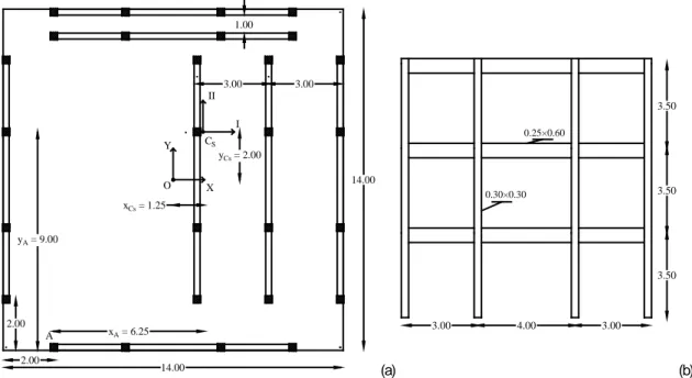
The second case study comprises a 3-storey isotropic building complying with the mechanical and material characteristics defined in Section 2. The plan view of a typical storey of the considered structure is presented in Figure 4a. The building consists of identical planar frames, shown in Figure 4b, which are connected at the floor levels by rigid horizontal diaphragms. The modulus of elasticity is considered to be 25 GPa, the height of each storey is 3.50 m, the cross section dimensions of the columns are 0.30 × 0.30 m2 and those of the beams are 0.25 × 0.60 m2. The mass of each storey is equal
to 143 ton.
Since the vertical resisting elements have proportional stiffness matrices, the building is an isotropic building and has a real elastic axis and principal bending directions. The lateral stiffness matrix with respect to the global reference system (X,Y,Z) is given by:
3 0 -6 0 4 5 -6 5 249 O O O O O O O O O K K K K K K K K K K ⋅ ⋅ ⋅ = ⋅ ⋅ ⋅ ⋅ ⋅ ⋅ (19)
Determination of the critical angle of seismic incidence in standardized procedures for the seismic safety assessment of 3D RC buildings
10 where K̲O is a 3×3 lateral stiffness matrix of an individual frame (Figure 4b).
The coordinates of the elastic axis, xCs = 1.25 m and yCs = 2.00 m, were calculated in
the global coordinate system shown in Figure 4a. The angle ω between the principal direction I and the global reference axis X is equal to zero since all resisting elements have their local structural axes parallel to the X and Y structural axes. The lateral stiffness matrix with respect to the principal bending planes defined by Eq. (9) is then:
, , 3 0 0 0 4 0 0 0 230.75 O I II III O O K K K K ⋅ = ⋅ ⋅ (20)
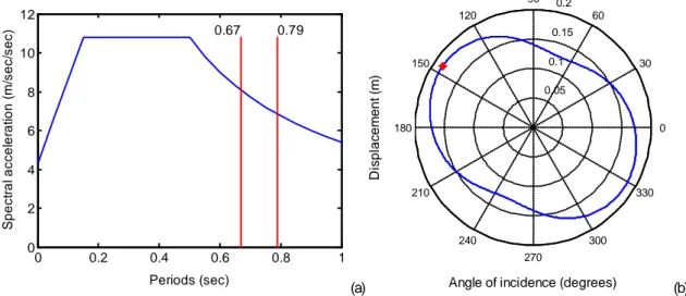
The principal periods, which coincide with the periods along the X and Y structural axes (Figure 4a) are TI = 0.79 sec and TII = 0.67 sec. Consequently, the fundamental
uncoupled periods for all directions fall into the third branch of the spectrum (Figure 5a) and the displacement of the diaphragms are given by Eq. (16). Finally, F(α’) is expressed by: ( ') 2.5 C unc T F a S T = ⋅ ⋅ ⋅
α
(21)where Τunc is given by Eq. (4).
By inserting the coordinates of the points and the values of the principal stiffness matrix into Eq. (16), the resultant displacement of point A (shown in Figure 4a) can be calculated for every value of α’. The derivative and the equation, solved with the mathematical software Maple [17], led to an ASIcrit with respect to the principal
reference system of α’ = 145.6o. The ASI
crit α with respect to the structural coordinate
system X-Y is equal to α’ since ω =0o.
14.00 14.00 O X Y A CS I II yCs = 2.00 xCs = 1.25 xA = 6.25 yA = 9.00 1.00 3.00 3.00 2.00 2.00 (a) 3.50 3.50 3.50 3.00 4.00 3.00 0.30×0.30 0.25×0.60 (b)
Figure 4: Plan view of a typical floor of the 3-storey isotropic building (a) and typical frame (b); dimensions are in meters.
In order to verify this result obtained analytically, the behaviour of the structure was also simulated using the software OpenSees [18]. A parametric analysis was performed by varying the ASI of the horizontal forces determined from the response spectrum. The forces were assumed to be distributed triangularly and applied at the
Determination of the critical angle of seismic incidence in standardized procedures for the seismic safety assessment of 3D RC buildings
11 geometrical centres of the floor diaphragms. It is mentioned that the pattern of the distribution of the lateral forces does not influence the results because of the isotropic properties of the structure. Accidental eccentricities were not taken into account. The value of the forces was calculated for each ASI from the uncoupled fundamental period of the structure along the respective direction. The evolution of the displacement of point A for all the ASIs is shown in Figure 5b. The maximum displacement was achieved for ASI equal to 146o, thus validating the analytical result. It is also noticed
that in accordance with relevant studies [7], the maximum demand was not obtained for the X or Y structural axes of the building even for buildings with apparent principal directions. 0 0.2 0.4 0.6 0.8 1 0 2 4 6 8 10 12 Periods (sec) S pec tr al ac c el er at ion ( m /s ec /s ec ) 0.67 0.79 (a) 0.05 0.1 0.15 0.2 30 210 60 240 90 270 120 300 150 330 180 0
Angle of incidence (degrees)
D is pl ac em ent ( m ) (b)
Figure 5: The response spectrum with the principal periods (a) and the displacement of
column A for LFA for every ASI (maximum displacement is noted with the red marker) (b).
5. CONCLUDING REMARKS
The current paper develops an analytical methodology to determine the critical angle of seismic incidence in single storey buildings and isotropic multi-storey buildings analysed with LFA. Given that past research has shown that each demand parameter obtains its maximum value for a different ASI, the proposed approach only examined the top displacement of the structure, a demand parameter that was found suitable to describe global 3D structural performance. The validity of the developed framework was demonstrated by two case studies: a single storey building and a 3-storey isotropic building. Although in both case studies the parameter under consideration was the maximum total displacement, the methodology and the results can be extended for interstorey drifts. The applicability of the proposed framework is straightforward since it depends only on the materials and the geometrical characteristics of the structure and may also integrate different values of the external static force. An additional advantage of the methodology is that it is valid for forces applied at any point of the diaphragm, thus allowing for the consideration of accidental eccentricities.
Although the presented framework introduces a direct methodology to determine the ASIcrit, its applicability is still bounded by the requirement for the existence of a real
elastic axis. Since the elastic axis is a very good descriptor of a building and allows the determination of its static behaviour independently of the external loading [11], efforts have been made to extend and generalize the concept of the elastic axis for general multi-storey buildings. Two different methodologies can be found in the literature that deal with the approximation of the elastic axis for multi-storey buildings [11], [19], [20]. The application of the proposed expression with exploitation of those concepts will be the focus of future research.
Determination of the critical angle of seismic incidence in standardized procedures for the seismic safety assessment of 3D RC buildings
12
6. ACKNOWLEDGEMENTS
The first author would like to acknowledge the financial support from the Foundation of Science and Technology (FCT) of Portugal through the grant PD/BD/113681/2015.
7. REFERÊNCES
[1] EN1998-3 (2005) Assessment and retrofitting of buildings. Design of structures for
earthquake resistance. European Committee for Standarization.
[2] Rosenblueth, E., and H. Contreras (1977) Approximate design for multi-component earthquakes. Journal of the Engineering Mechanics Division 103(5), 895–911.
[3] Newmark, N. (1975) Seismic Design Criteria for Structures and Facilities: Trans-Alaska Pipeline System. U.S. National Conference in Earthquake Engineering. Ann Arbor, Michigan.
[4] Lopez, O. A., A. K. Chopra and J. J. Hernandez (2001) Evaluation of combination rules for maximum response calculation in multicomponent seismic analysis.”
Earthquake Engineering & Structural Dynamics 30(9), 1379–98.
[5] Tsourekas A. G. and A. M. Athanatopoulou (2013) Evaluation of existing combination rules for the effects caused by three spatial components of an earthquake, KSCE J. Civ. Eng. 17(7), 1728–1739.
[6] Kostinakis, K. G., A. M. Athanatopoulou and V. S. Tsiggelis (2013) Effectiveness of percentage combination rules for maximum response calculation within the context of linear time history analysis. Engineering Structures 56, 36–45.
[7] Morfidis, K. E., A. M. Athanatopoulou and I. E. Avramidis (2008) Effects of seismic directivity within the framework of the lateral force procedure. 14th World
Conference on Earthquake Engineering. Beijing, China.
[8] EAK. (2000) Greek Code for Earthquake Resistant Design of Structures. Ministry of Environment, Planning and Public Works.
[9] Quadri, S. A. and M. Madhurin (2014) Investigation of Critical Angle of Seismic Incidence for the Analysis of RCC Frames. 12th IRF International Conference. Pune, India.
[10] Roussopoulos, A. (1932) Distribution of horizontal forces by a rigid plate in spatial structures: case of seismic forces, their distribution and regime. Technika
Chronika, Technical Chamber of Greece 17, 871–84 (In Greek).
[11] Makarios, T. K., and K. Anastassiadis (1998) Real and fictitious elastic axes of
multi-storey buildings: Theory. Structural Design of Tall and Special Buildings 7(1), 33–55.
[12] Anastassiadis, K. (1989) Antiseismic Structures. Volume I. Thessaloniki, Greece
(In Greek): ZITI.
[13] Riddel, R., and J. Vasquez (1984) Existence of Centers of Resistance and
Torsional Uncoupling of Earthquake Response of Buildings. 8th World Conference
on Earthquake Engineering 187–94. San Francisco, USA.
[14] Athanatopoulou, A. M. and I. N. Doudoumis (2008) Principal Directions under
Lateral Loading in Multistorey Asymmetric Buildings. Structural Design of Tall and
Special Buildings 17(4): 773–94.
[15] Anastassiadis, K. (1985) Caractéristiques élastiques spatiâles des bâtiments à
étages. Annales de I’ I.T.B.T.P. No 435.
[16] EN1998-1. (2004) General rules, seismic actions and rules for buildings. In Design
of structures for earthquake resistance. European Committee for Standarization.
[17] Maple 18 (2002) “Maplesoft, a division of Waterloo Maple Inc.” Waterloo, Ontario.
[18] McKenna, F., Fenves, G., Jeremic, B. and Scott, M. (2000) Open System for
Earthquake Engineering Simulation. Available at: http://opensees.berkeley.edu/.
[19] Marino, E. M., and P. P. Rossi (2004) Exact Evaluation of the Location of the
Optimum Torsion Axis. Structural Design of Tall and Special Buildings 13(4), 277– 90.
[20] Doudoumis, I. N., and A. M. Athanatopoulou (2008) Invariant Torsion Properties of
Multistorey Asymmetric Buildings. Structural Design of Tall and Special Buildings 17(1), 79–97.