Miguel Alexandre Castanheira Marques
Licenciado em Ciências da EngenhariaElectrotécnica e deComputadores
Sistema on-line de detecção de avarias em
motores de indução baseado em PCA
Dissertação para obtenção do Grau de Mestre em Engenharia Electrotécnica e de Computadores
Orientador: Doutor João Francisco Alves Martins, Professor
Auxiliar, Faculdade de Ciências e Tecnologia da Universidade
Nova de Lisboa
Co-orientador: Mestre Rui Dias Jorge, EFACEC
Júri:
Presidente: Doutor João Miguel Murta Pina Arguentes: Doutor Duarte de Mesquita e Sousa
Doutor Vitor Manuel de Carvalho Fernão Pires
Miguel Alexandre Castanheira Marques
BSc in Electrical and Computer EngineeringOn-line system for faults detection in
induction motors based on PCA
Dissertation to obtain the degree of Master in Electrical and Computer Engineering
Supervisor: João Francisco Alves Martins, PhD, Science and
Tecnology Faculty from Universidade Nova de Lisboa
Co-supervisor: Rui Dias Jorge, MSc, EFACEC
Evaluation Board:
President: Professor João Miguel Murta Pina Opponents: Professor Duarte de Mesquita e Sousa
Professor Vitor Manuel de Carvalho Fernão Pires
Sistema on-line de detecção de avarias em motores de indução baseado em PCA COPYRIGHT 2012 Miguel Alexandre Castanheira Marques
COPYRIGHT 2012 Faculdade de Ciências e Tecnologia COPYRIGHT 2012 Universidade Nova de Lisboa
A Faculdade de Ciências e Tecnologia e a Universidade Nova de Lisboa têm o direito, perpétuo e sem limites geográficos, de arquivar e publicar esta dissertação através de exemplares impressos reproduzidos em papel ou de forma digital, ou por qualquer outro meio conhecido ou que venha a ser inventado, e de a divulgar através de repositórios científicos e de admitir a sua cópia e distribuição com objectivos educacionais ou de investigação, não comerciais, desde que seja dado crédito ao autor e editor.
I I express my deep thanks to the Department of Electrotechnical Engineering from Science and Technology Faculty who contributed to this work and for my personal and professional formation.
To UNINOVA, Instituto de Desenvolvimento de Novas Tecnologias for financial and
institutional support in the acquisition of the electric motors.
My sincere thanks to my advisor, Prof. João Martins, for his singular personality and the technical and scientific teachings that collaborated to this work.
To Eng. Rui Dias Jorge for the attention, help and openness that always showed when I needed.
To Eng. Luís Filipe Mendes for the precious help and support throughout this work. To the rest of EFACEC's working group by the goodwill and support.
My deep thanks to my friends Bruno Valente, Fábio Júlio, Flávio Diniz, Paulo Pereira and Pedro Gomes my thanks for your friendship, support and for having accompanied me during this years.
I wish to thank to Bruno Caixinha, Bruno Duarte, Carlos Calmeiro, Carlos Carvalho, Catarina Domingues, Catarina Lucena, Fábio Alves, Gonçalo Azevedo, João Chalaça, Luís Lopes, Luís Miranda, Micael Simões, Pedro Almeida, Pedro Oliveira, Raquel Melo, Ricardo Legas, Ricardo Mendonça, Vanessa Chamorrinha, Vitor Astúcia, my faculty friends and colleagues for their assistance and the funny moments that we passed in these years.
To my friends from the Department of Electrotechnical Engineering and the IEEE Student
Branch, David Inácio and Pedro Pereira, for their friendship and support.
After completing this work could not fail to deeply thanks to my parents, my sister and my grandparents Margarida and Frutuoso for everything they did for me and the way it contributed to my education and happiness.
Finally, I want to thank in a very special way to Rita, for the love, encouragement and understanding that has always shown.
III Actualmente na indústria existem muitos processos onde a intervenção humana é substituída por máquinas eléctricas, especialmente máquinas de indução devido ao seu baixo custo, elevado desempenho e robustez. Embora, a máquina de indução seja um dispositivo altamente fiável, também é susceptível a falhas. Portanto, o estudo do estado da máquina de indução é essencial para reduzir custos financeiros e humanos.
As falhas em máquinas de indução podem ser divididas basicamente em dois tipos: falhas eléctricas e falhas mecânicas. As falhas eléctricas representam entre 40% e 50% das falhas reportadas e também podem ser divididas basicamente em dois tipos: desequilíbrios no estator e barras quebradas no rotor.
Tendo em conta a elevada dependência das máquinas eléctricas, é necessário dispor de sistemas de diagnóstico e monitorização para máquinas de indução. É apresentado neste trabalho um sistema on-line para detecção e diagnóstico de falhas eléctricas em motores de indução com base na monitorização das correntes de alimentação da máquina. O objectivo principal é detectar e identificar a presença de barras quebradas no rotor e curto-circuitos no estator da máquina. A presença de falhas na máquina provoca diferentes perturbações nas correntes de alimentação. Portanto através do uso de um referencial fixo, como é o caso da transformada αβ é possível extrair e manipular os resultados obtidos a partir das correntes de alimentação utilizando a decomposição em valores e vectores próprios.
Palavras-Chave: máquina de indução, diagnóstico, detecção de falhas, monitorização de
condição, análise dos componentes principais, PCA, valor próprio, vector próprio
V Nowadays in the industry there many processes where human intervention is replaced by electrical machines, especially induction machines due to his robustness, performance and low cost. Although, induction machines are a high reliable device, they are also susceptible to faults. Therefore, the study of induction machine state is essential to reduce human and financial costs.
The faults in induction machines can be divided mainly into two types: electrical faults and mechanical faults. Electrical faults represent between 40% and 50% of the reported faults and can be divided essentially in 2 types: stator unbalances and broken rotor bars.
Taking into account the high dependency of induction machines and the massive use of automatic processes the industrial level, it is necessary to have diagnostic and monitoring systems these machines. It is presented in this work an on-line system for detection and diagnosis of electrical faults in induction motors based on computer-aided monitoring of the supply currents. The main objective is to detect and identify the presence of broken rotor bars and stator short-circuits in the induction motor. The presence of faults in the machine causes different disturbances in the supply currents. Through a stationary reference frame, such as αβ transform it is possible to extract and manipulate the results obtained from the supply currents using Eigen decomposition.
Keywords: induction motor, diagnosis, fault detection, condition monitoring, principal
component analysis, PCA, eigenvalue, eigenvector
VII
Sumário ... III
Abstract ... V
Table of Contents ... VII
List of Figures ... XI
List of Tables ... XV
List of Symbols ... XV
Acronyms... XVII
Chapter 1:Introduction ... 1
1.1 Motivation ... 1
1.2 Overview ... 2
1.3 Objectives and Contributions ... 4
1.4 Outline of Dissertation ... 4
1.5 Publications ... 5
Chapter 2:Induction Machines Faults ... 7
2.1 Introduction ... 7
2.2 Electrical Faults ... 10
2.2.1 Stator Faults ... 10
2.2.2 Rotor Faults ... 15
2.3 Mechanical Faults ... 19
2.3.1 Bearing Faults ... 19
2.3.2 Air-gap Eccentricity ... 20
Chapter 3:Fault Detection and Diagnosis in Induction Machines ... 23
3.1 Introduction ... 23
3.1.1 Terminology and Definitions... 24
3.1.2 Fault classification ... 24
3.1.3 Classification of the FDD methods ... 25
VIII
3.1.4 Maintenance ... 27
3.2 Why Condition-Based Maintenance? ... 29
3.2.1 Main Functions and Characteristics of a CMS ... 30
3.3 On-line Condition Monitoring ... 31
3.4 FDD Techniques used in Induction Machines ... 32
3.4.1 Non-Electrical Techniques ... 33
3.4.2 Electrical Techniques ... 36
3.5 Synthesis ... 45
Chapter 4: TPU: Hardware and Software Description... 47
4.1 Introduction ... 47
4.2 Hardware Architecture ... 49
4.2.1 Processing and communications module ... 50
4.2.2 Power supply module ... 50
4.2.3 Digital I/O ... 50
4.2.4 A.C. Analog I/O ... 51
4.3 Software Architecture ... 51
Chapter 5: MMoDiS : A PCA based Fault Detection and Diagnosis System ... 55
5.1 Principal Component Analysis (PCA) ... 55
5.2 MMoDiS as an On-line Condition Monitoring System ... 59
5.2.1 Pre-Operational Requirements ... 60
5.3 Functional Vision ... 60
5.4 Architectural Diagram ... 64
5.5 Used Technologies ... 65
5.6 Routines Description ... 66
Chapter 6:Results ... 71
6.1 Experimental Set Up ... 71
6.2 Simulation Results ... 74
6.2.1 Healthy Motor ... 75
6.2.2 Stator Faults ... 77
IX
6.3 Experimental Results ... 88
6.3.1 Healthy Motor ... 88
6.3.2 Stator Faults ... 90
6.3.3 Rotor Faults ... 97
Chapter 7:Conclusions and Future Work ... 101
7.1 Summary of the Thesis ... 101
7.2 Conclusions ... 102
7.3 Recommendations for future work ... 104
Bibliography ... 107
XI
Figure 2.1 – Components of a squirrel-cage induction motor ... 7
Figure 2.2 – Types of faults in induction machines ... 8
Figure 2.3 – Faults distribution in induction machines ... 9
Figure 2.4 – Events that contribute for induction motor faults. ... 10
Figure 2.5 - Typical insulation damage leading to inter-turn short circuit of the stator windings in three-phase induction motors. ... 11
Figure 2.6 - Inter-turn short circuit of the stator winding in three-phase induction motors. ... 13
Figure 2.7 – Two types of squirrel-cage rotors. (A) Cast rotor (B) Fabricated rotor ... 15
Figure 2.8 – Fabricated rotor of a 5 MW rated power (Pel) machine with multiple broken rotor bars .. 16
Figure 2.9 – (A) Bar housed in a slot without damage (B) Bar housed in a slot with damage ... 18
Figure 2.10 – Schematic diagram of a rolling-element bearing ... 20
Figure 2.11 - Different types of eccentricity (border line is the stator inner ring, round rotor is in grey). (a) Without eccentricity (b) Static eccentricity (c) Dynamic eccentricity ... 21
Figure 3.1 – Time-dependency of faults. (a) Abrupt fault (b) Intermittent fault (c) Incipient fault ... 24
Figure 3.2 – Fault detection methods classification ... 25
Figure 3.3 - Schematic diagram of model-based methods ... 25
Figure 3.4 – Expert System structure ... 26
Figure 3.5 – Fault diagnosis methods classification ... 26
Figure 3.6 – Differences between on-line and off-line methodologies ... 31
Figure 3.7 – Basic modules from a CMS ... 31
Figure 3.8 – Alternative schematic diagram for on-line condition monitoring ... 32
Figure 3.9 – Experimental apparatus for vibration measurements in electrical machines ... 33
Figure 3.10 - Thermography of an electrical motor ... 35
Figure 3.11 – Chemical monitoring system implemented by Carson et al. ... 36
Figure 3.12 - Equipment used to measure the axial flux in an electrical machine ... 37
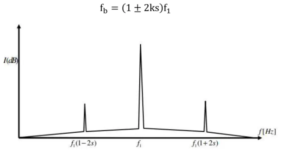
Figure 3.13 – Ideal current spectrum of a healthy machine ... 39
Figure 3.14 – Ideal current spectrum in a motor with broken rotor bars ... 40
Figure 4.1 – List of TPU x220 line products ... 47
Figure 4.2 – Illustration of the TPU front panel ... 48
Figure 4.3 – Hardware Architecture of the TPU x220 products ... 49
Figure 4.4 – Software architecture of the TPU x220 products ... 52
XII
Figure 4.5 – Basic architecture of the Cerberus application framework ... 53
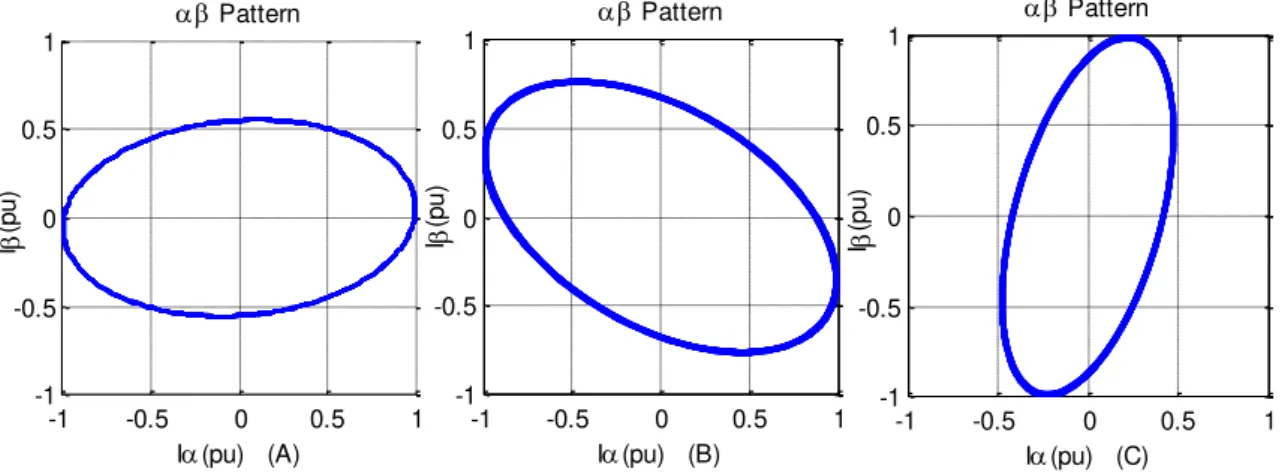
Figure 5.1 - Healthy motor input current αβ–vector pattern ... 58
Figure 5.2 – Stator fault input current αβ-vector patterns. (A) stator fault in phase A (B) stator fault in phase B (C) stator fault in phase C ... 58
Figure 5.3 – Rotor fault input current αβ-vector pattern ... 59
Figure 5.4 – Global vision of MMoDiS ... 59
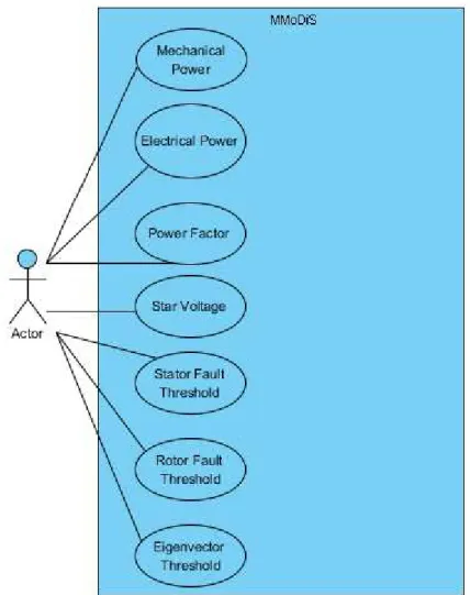
Figure 5.5 – Types of actor that exists in the developed system ... 61
Figure 5.6 – Use Case diagram of the User profile ... 62
Figure 5.7 – Use Case diagram of the Administrator profile ... 63
Figure 5.8 – Architectural Diagram of MMoDiS ... 64
Figure 5.9 – Used Technologies in the implementation of MMoDiS ... 65
Figure 5.10 – Activity diagram related to the workflow of MMoDiS ... 66
Figure 5.11 – Activity diagram of the hardware configuration block ... 66
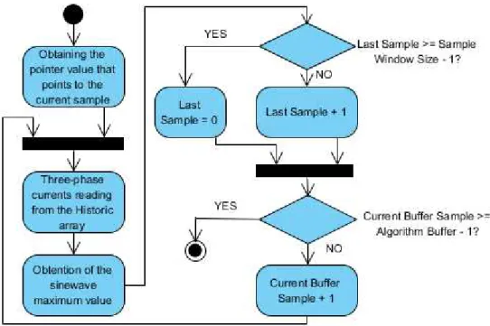
Figure 5.12 – Activity diagram of the Data Acquisition module ... 66
Figure 5.13 – Activity diagram of the three-phase current reading module ... 67
Figure 5.14 – Data acquisition process ... 67
Figure 5.15 – Sliding window used in the algorithm ... 68
Figure 5.16 – Activity diagram of PCA module... 69
Figure 6.1 – Schematic diagram of the experimental set up used ... 71
Figure 6.2 – Experimental apparatus used in this work ... 72
Figure 6.3 – Nameplate data of the induction machine (left) and dc machine (right) ... 72
Figure 6.4 – Equipment used for torque and speed measurements ... 73
Figure 6.5 – Example of a broken rotor bar fault applied artificially ... 73
Figure 6.6 – Example of the application of a stator fault ... 74
Figure 6.7 – (A) Stator currents of the induction machine in nominal operation (B) Simulated αβ -vector Transformation (C) Current A spectrum ... 75
Figure 6.8 – (A) Stator currents of the induction machine with an applied torque of 50% of the nominal torque (B) Simulated αβ-vector Transformation (C) Current A spectrum ... 76
Figure 6.9 – (A) Stator currents of the induction machine with an applied torque of 0% compared with the nominal torque (B) Simulated αβ-vector Transformation (C) Current A spectrum ... 77
Figure 6.10 - (A) Stator currents of the induction machine in nominal operation with 18% of the phase A stator windings short-circuited (B) Simulated αβ-vector Transformation ... 78
Figure 6.11 – Variation of eigenvalues over the computing cycles ... 79
Figure 6.12 - (A) Stator currents of the induction machine in nominal operation with 7% of the phase A stator windings short-circuited (B) Simulated αβ-vector Transformation ... 80
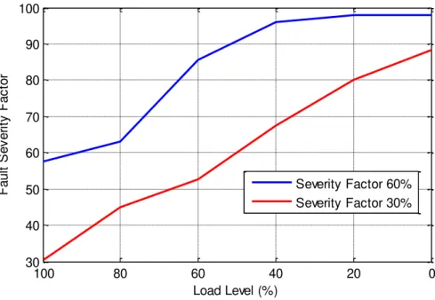
XIII Figure 6.14- Evolution of the fault severity factor with the motor load level for the case of a motor with 7% (red) and 14% (blue) of the stator windings short-circuited ... 81 Figure 6.15 – Evolution of the rated speed in 3 different situations: healthy condition and two fault situations ... 82 Figure 6.16 –αβ-vector Transformation for different fault severity factors applied to the phase B ... 82 Figure 6.17 - Evolution of the fault severity factor with the motor load level for the case of a motor with 7% (red) and 14% (blue) of the stator windings short-circuited ... 83 Figure 6.18 - Evolution of the rated speed in 3 different situations: healthy condition and two fault situations in the phase B ... 83 Figure 6.19 - αβ-vector Transformation for different fault severity factors applied to the phase C ... 84 Figure 6.20 – (A) Evolution of the fault severity factor with the motor load level for the case of a motor with 7% (red) and 14% (blue) of the stator windings short-circuited (B) rated speed in 3 different situations: healthy condition and two fault situations in the phase C ... 85 Figure 6.21 - (A) Stator currents of the induction machine in nominal operation with 30% of the phase A rotor windings short-circuited (B) Simulated αβ-vector Transformation ... 86 Figure 6.22 - (A) Stator currents of the induction machine in nominal operation with 50% of the phase A rotor windings short-circuited (B) Simulated αβ-vector Transformation ... 86 Figure 6.23 – Variation of the eigenvalues in function of computation cycles ... 87 Figure 6.24 - Evolution of the fault severity factor with the motor load level for the case of a motor with 30% (red) and 50% (blue) of the phase A rotor windings short-circuited ... 87 Figure 6.25 – Temporal evolution of the machine rated speed in 3 different situations. ... 88 Figure 6.26 - (A) Stator currents of the machine in nominal operation (B) Experimental αβ-vector Transformation (C) Current A spectrum ... 89 Figure 6.27 - (A) Stator currents of the machine with 50% of the nominal torque (B) Experimental αβ -vector Transformation (C) Current A spectrum ... 89 Figure 6.28 – Illustration of the variable resistors used. (A) Parameters of the resistor (B-1) Impedance for the SF = 60% (B-2) Impedance for the SF = 30% ... 90 Figure 6.29 – Experimental results obtained for a stator fault situation in nominal operation with a SF = 30 % in the phase A (A) Stator currents of the machine (B) Experimentalαβ Transformation ... 91 Figure 6.30 – Experimental results obtained for a stator fault situation in nominal operation with a SF = 60 % in the phase A (A) Stator currents of the machine (B) Experimentalαβ Transformation ... 91 Figure 6.31 - Evolution of the fault severity factor with the motor load level. The blue line is for a SF = 60% and the red line for a SF = 30% ... 92 Figure 6.32 –HMI of the TPU with the indication of a stator fault in the phase 1 (A)... 92
XIV
Figure 6.34 – Experimental results obtained for a stator fault situation in nominal operation with a SF = 60 % in the phase B (A) Stator currents of the machine (B) Experimentalαβ Transformation ... 93 Figure 6.35 –HMI of the TPU with the indication of a stator fault in the phase 2 (B) ... 94
Figure 6.36 – Experimental results obtained for a stator fault situation in nominal operation with a SF = 30 % in the phase C (A) Stator currents of the machine (B) Experimentalαβ pattern ... 94 Figure 6.37 – Experimental results obtained for a stator fault situation in nominal operation with a SF = 60 % in the phase C (A) Stator currents of the machine (B) Experimental αβ Transformation ... 95 Figure 6.38 –HMI of the TPU with the indication of a stator fault in the phase 3 (C) ... 95
Figure 6.39 - Variation of the eigenvalues over the computation cycles in a stator fault situation (A) Stator fault with a SF = 30% (B) Stator fault with a SF = 60% ... 96 Figure 6.40 - Experimental results obtained for the machine with 1 broken rotor bar (A) Stator currents of the machine (B) Experimental αβ Transformation... 97 Figure 6.41 - Experimental results obtained for the machine with 6 broken rotor bars (A) Stator currents of the machine (B) Experimental αβ Transformation ... 98 Figure 6.42 - Variation of the eigenvalues over the computation cycles in a rotor fault situation (A) 1 broken rotor bar (B) 6 broken rotor bars ... 98 Figure 6.43 –HMI of the TPU with the indication of a rotor fault ... 99
Figure 6.44 - Evolution of the fault severity factor with the motor load level. The blue line is for a rotor fault situation with 6 BRB and the red line for 2 BRB ... 99
XV
Table 2.1 – Comparison between surveys of faults distribution in electrical machines. ... 8
Table 3.1 – Comparison of maintenance techniques ... 28
Table 3.2- Comparison between FDD methods ... 45
Table 5.1 – Specification of the actor profiles ... 61
Table 6.1 – Summary of the conducted tests ... 74
Table 6.2 – Comparison between the eigenvectors obtained in simulation and experimental tests ... 96
Symbol Description Units
A,B,C Symbology used to identify the phases of a three-phase current system
bd Ball diameter mm
E Correlation matrix
f1 Electrical supply frequency Hz
fb,o, fb,i, fb,r Bearing damages fault frequency Hz
fecc, fslot+ecc Air-gap eccentricities fault frequency Hz
fsc Stator windings fault frequency Hz
fr Mechanical rotor speed Hz
I Identity matrix
ia, ib, ic Motor supply currents A
List of Tables
XVI
iM Maximum value of the supply phase current A
iα, iβ αβ stator current components A
Inom Nominal Current of dc generator A
k, m Positive integer number n Number of bearing balls
N Motor Rated Speed RPM
nd Rotating eccentricity order
nw Stator MMF harmonic order
p Number of pole pairs
pd Bearing pitch diameter mm
Pel Electrical Power kW, MW
Pmec Mechanical Power HP
R Rotor slots number
s Slip per unit %
S Apparent Power kVA
SF, SF1BB, SF6BB Fault Severity Factor %
t Time variable s, ms
u Eigenvectors X Data matrix
β Contact angle of the balls on the races
λ Eigenvalues
XVII AC Alternate Current
ADC Analog-Digital Converter AI Artificial Intelligence ARM Advanced RISC Machine BM Breakdown Maintenance C# C Sharp
CBM Condition Based Maintenance CCS Code Composer Studio Cerberus Framework of TPU x220 CM Condition Monitoring
CMS Condition Monitoring System CPU Central Processing Unit CT Current Transformer DC Direct Current
De Lorenzo Italian company that develop educational systems DLL Dynamic Link Library
DMA Direct Memory Access DNP Distributed Network Protocol DSP Digital Signal Processor DTC Direct Torque Control EFACEC Portuguese company EMIF External Memory Interface
XVIII
EPRI Electric Power Research Institute FDD Fault Detection and Diagnosis FFT Fast Fourier Transform
GOOSE Generic Object Oriented Substation Events GPIO General Purpose Input/Output
HMI Human Machine Interface HP Horse Power
HV High Voltage I/O Input/Ouput
IAS Industry Applications Society
IDE Integrated Development Environment IEC Internacional Electrotechnical Commission IEEE Institute of Electrical and Electronic Engineers IFAC International Federation of Automatic Control IMS Intelligent Maintenance System Group IRIG Inter-Range Instrumentation Group
ISO Internacional Organization for Standardization ISR Interrupt Service Routine
LCD Liquid Crystal Display LED Light-Emitting Diode MATLAB MATrix LABoratory
MCSA Motor Current Signature Analysis
XIX OMAP Open Multimedia Applications Platform
OOL Object Oriented Language PC Principal Components
PCA Principal Component Analysis PdM Predictive Maintenance
PLC Programmable Logic Controller PM Preventive Maintenance
PWM Pulse Width Modulation
RCM Reliability-Centered Maintenance RISC Reduced Instruction Set Computing RMS Root Mean Square
RPM Revolutions per Minute RTDB Real-Time Data Base
SDRAM Synchronous Dynamic Random Access Memory SNTP Simple Network Time Protocol
SVD Single Value Decomposition Syrius Framework of TPU x220
TCP/IP Transmission Control Protocol/Internet Protocol TPU Terminal Protection Unit
UML Unified Modelation Language UMP Unbalanced Magnetic Pull VMM Vienna Monitoring Method VT Voltage Transformer
XX
1
Chapter 1
In this introductory chapter, it is presented the context of the work that resulted in this thesis. The Section 1.1 refers to the motivation for the theme of this work and in Section 1.2 is made a general description of the state-of-the-art. In Section 1.3 are listed the objectives and the contributions of this research work and in Section 1.4 it is made reference to the organization of the thesis.
1.1
Motivation
Rotating electrical machines, especially three-phase induction machines, perform critical functions as part of industrial processes, mainly due to its simplicity of construction, low production cost, robustness and reduced maintenance compared for example, with dc machines or
synchronous machines. It is estimated that about 60% of the electrical energy produced in the United States is consumed by electrical machines, such as synchronous machines, dc machines or
induction machines [1]. In addition, induction motors typically consume 40 % to 50 % of all electrical energy produced in a country [2]. Therefore induction motors have a special role in the economy of the industrialized countries.
However despite the robustness of the induction motor, any electromechanical device presents erosion and need maintenance to prevent that faults put in risk the equipment and
manufacturing processes. The task of discovering the state of the machine’s components is
complicated and a time consuming task, because it is necessary the presence of technical experts and sometimes it is necessary to replace the failed machine for an healthy machine to proceed to its repair. In the case of large-sized machines this task becomes even more complicated by the fact that sometimes it is not possible to replace the machine and the tools necessary to perform the repairs are expansive and not easy to carry. All these mentioned difficulties have human and economic costs, such as the need to stop industrial processes and the waste of raw materials. Due to its importance, such equipment needs special attention to assure his performance, reliability and efficiency and to avoid human and economic costs [3].
According to Tavner et al. [3], the annual investment per employee in machinery in
certain areas, such as oil and gas is growing. The same authors stated that the average annual costs on maintenance were 80% of the amount annually invested in plant and machinery.
Taking into account the reports published in [3] is urgent to develop intelligent systems that detect the presence of faults in the machines in order to reduce maintenance costs. These systems will allow the possibility of scheduled maintenance and predict the need for maintenance before serious deterioration or fault occurs, making it possible to increase the reliability of equipment, the improvement of his behavior and performance [4].
1.2
Overview
The first public developments in this area came in 1935 with the deduction of expressions for induction motors with unbalances in the input voltage source [5]. In the following years the scientific activity in the area was related only to the detection of defects in squirrel-cage rotors [6-8]. In the early of the 1960s, some research works expressed a concern in studying the behavior of the induction motors in applications related to its protection [9, 10].
According to Penman and Stavrou [11], in the 1970s, was established a generalized rotating field theory with the purpose of demonstrate that the presence of asymmetries in the machine will lead to the appearance of induced currents in the stator windings at frequencies close to the supply frequency of the machine. In this decade was also proposed [12] the use of a set of thermocouples with the objective of monitoring the temperature in the rotor bars and end-rings, in order to protect them from overheating. The proposed system was implemented in high power induction and synchronous machines.
Only in the 1970s and 1980s the researchers have intensified efforts in analyzing the effects that caused the appearance of faults in induction machines. Initially the study of these causes was performed in laboratory tests based on measurements of electric or magnetic quantities. This was made only by observation of the measurements, without the intervention of any type of device with computing power [13-18].
In 1983, Dey [19] developed the first on-line protection system based on the measurements of the machine axial flux with the aid of a micro-computer. After this, Thomson and Stewart [20] in 1987 present an on-line fault detection system based on spectral analysis of the input current. However, the proposed system only detected broken rotor bars and air-gap eccentricities and was tested only at a laboratory level. In 1989 Kliman et al. [21] also developed
an on-line system for fault detection, similar to the system proposed by Thomson and Stewart [20], but the difference was in the spectral analysis. This method uses input current and axial flux to make the spectral analysis. Kliman et al. also patented in the United States, two applications
[22, 23] for fault detection and diagnosis in induction machines.
Siyambalapitiya and McLaren [4] in 1990 presented a study that suggests the use of methods to quantify the savings achieved through the implementation of a monitoring system for large induction machines in industrial environments. The study also suggests the possibility to evaluate the economic viability of using a specific monitoring system, depending on the desired reliability for the system.
During the 1990s to the present, fault detection and diagnosis (FDD) in induction
machines is a research area that had a great evolution, as seen by the number of proposed methodologies, such as neural networks [24-26], finite element methods [27-29], current space patterns [30-35], fuzzy logic [36, 37], parameter estimation [38-40], spectral analysis [41-45], wavelets transform [46, 47], negative sequence components [48], mathematical methods [49-51], vibration monitoring [52, 53] and artificial intelligence (AI) techniques [54].
However, although there is a large variety of techniques for detection and diagnosis there are some gaps in this area that have not yet been filled. Firstly due to the variety of electrical machines, the application of fault detection and diagnosis (FDD) techniques becomes more
difficult. Secondly the fact that most of the research works in this field are only implemented at laboratory level, there is no integrated product that is ready to be connected to any induction machine.
Currently the types of techniques used or developed for condition monitoring and fault detection are almost the same techniques used at 10 years ago. However, due to major developments in terms of computing power of microprocessors and communication technologies, the direction of research in the diagnosis and detection of faults in electrical machines, points to the use of FDD methods based on on-line non-invasive measurements. This type of measurement
1.3
Objectives and Contributions
In the context of condition monitoring systems (CMS), where a continuous evaluation of
the equipment health during its serviceable life is made while the machine is running, the main objective of the present work is the development of an on-line system for detection and diagnosis of electrical faults in three-phase induction motors. To achieve the main objective the present work refers to the development of a software infrastructure called Machine Monitoring and Diagnosis System (MMoDiS) that will be presented throughout this document. In synthesis there
were established the following objectives for this work:
1. Establish a theoretical treatment by reviewing the state-of-the-art in the field of faults in electrical machines and what techniques and methods are used for detection and identification of these faults;
2. Development of a software application based on EFACEC’s digital protection relay, the
Terminal and Protection Unit (TPU x220) that detects and diagnose electrical faults in
three-phase induction motors;
3. Simulation and experimental tests, using the developed software application in low power induction machines.
Concerning to the contribution of this research work, since that the existing systems for fault detection and diagnosis (FDD) in electrical machines are only implemented only at
laboratory level, the contribution of this work is the development of a software application integrated in an industry product that makes a continuous monitoring of the machine’s state.
1.4
Outline of Dissertation
The present work is composed by seven chapters and is organized in the following way:
Chapter 2
This chapter presents an overview of the faults that can be found in induction machines and a description of the possible causes and consequences produced by each fault.
Chapter 3:
In this chapter the first sections presents some terminologies and definitions that are used in the FDD field. There are also classified the FDD methods that currently
importance. Then, it is made a wide description of the methods that are currently used to detect and diagnose faults in induction machines.
Chapter 4:
The fourth chapter presents a major description of the Terminal Protection Unit (TPU) x220 used in this work. Initially is made and introduction to the equipment, why it
was developed and what is his objective. In the final sections it is made description of the hardware and software architecture.
Chapter 5:
This chapter explains the whole architecture of MMoDiS since the high-level
representations up to the description of the routines. Firstly, MMoDiS is presented as a
on-line condition monitoring systems and are also discussed his operational requirements. Secondly, it is described the conceptual model of the system, that basically is the idea that supports the developed solution. Then, it is explained the architectural diagram of the system and finally the description of the existing routines inside the system.
Chapter 6:
It will be shown an example of MMoDiS in operation, as well as several tests
made to the proposed solution. First is described the experimental setup used, and finally it is shown the simulation and experimental results obtained.
Chapter 7:
This chapter provides an overview of the work, reviews the contributions of this thesis and the possible future work.
Appendix A:
In appendix A is the code used for simulation purposes.
1.5
Publications
The following publications resulted from the research work presented in this Dissertation:
“Fault Detection and Diagnosis in Induction Machines: A Case Study”, Miguel Marques,
7
Chapter 2
This chapter presents a major description of the types of faults and their consequences to three-phase induction motors. Moreover, it explains the causes and the physical phenomena that lead to the appearance of faults in induction motors.
2.1
Introduction
In Figure 2.1 is presented a squirrel-cage induction machine and his components. Despite of an induction motor has several parts it is basically composed by a wound stator and by a wound or squirrel-cage rotor.
Figure 2.1 –Components of a squirrel-cage induction motor (adapted from [55]).
The stator is essentially composed by three parts: frame, lamination core and windings. The frame gives mechanical support to stator windings, the lamination core and the rotor bearings. The stator windings are composed by three coils equally distributed through the stator lamination core. The rotor is mainly composed by conductive rotor bars that are short-circuited, a shaft that gives mechanical support to the rotor and transmits the generated torque, a fan that cools the frame and bearings that reduce the friction.
Electrical machines and drive systems are subjected to many different types of faults. According to Nandi and Toliyat [56], faults in squirrel-cage induction machines can be classified as:
Figure 2.2 –Types of faults in induction machines (adapted from [56])
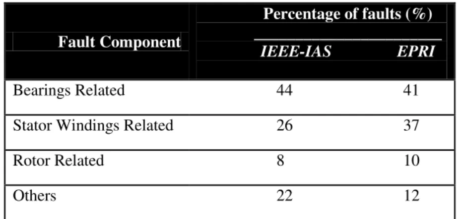
Several surveys have been carried out on the reliability of electrical machines. The distribution of faults in induction machines presented in Table 2.1 is based on published surveys [57, 58]. This table presents the surveys conducted by the Motor Reliability Working Group of the IEEE-IAS, which surveyed approximately 1000 motors [57] and the survey conducted by the
Electric Power Research Institute (EPRI) that covered about 5000 motors [58], approximately
97% of the surveyed machines were three-phase induction motors.
Fault Component
Percentage of faults (%) _______________________
IEEE-IAS EPRI
Bearings Related 44 41 Stator Windings Related 26 37 Rotor Related 8 10 Others 22 12
Table 2.1 –Comparison between surveys of faults distribution in electrical machines.
The IEEE-IAS survey and the EPRI report identified several faults mechanisms. Through
It should be noted that the provided data by the IEEE-IAS survey does not take into
account the fact that the machines work in different applications. So a fault occurrence depends on the application of the machine.
In Figure 2.3 is also reported another study published in the EPRI report [58] that
analyses more specifically the distribution of faults for each item listed in the Table 2.1.
Figure 2.3 –Faults distribution in induction machines
The percentage of faults associated exclusively with bearings is more than half of the graphic events. In the case of stator related faults, it is noted that insulation faults are the most common occurrences, they represent 27% in a total of 37 %. In the rotor side the most common faults are related to problems in the cage structure.
The IEEE-IAS survey [57] studied the causes that contributed to the occurrence of faults
Figure 2.4 –Events that contribute for induction motor faults.
The Figure 2.4 shows that the major contributing cause reported is normal deterioration from age. High vibration and poor lubrication were also reported as major contributors for the occurrence of faults which reinforce the results from Table 2.1 and Figure 2.3 where mechanical faults, such as bearing damages are the principal cause for the occurrence of faults in induction motors.
2.2
Electrical Faults
As stated before, electrical faults can be divided in stator and rotor faults. They represent between 40% and 45% of the reported faults. This section reports the most common electrical faults and their causes in three phase induction motors.
2.2.1
Stator Faults
Nandi and Toliyat [56] affirm that these faults are usually related to insulation failures and there are two types of faults in the stator windings that can be considered: asymmetries in the stator windings as an open phase fault and short circuits in the stator windings.
the machine impedance. As a result, the machine will operate with reduced torque. However, unbalanced current can also be caused by unbalance of the load and/or machine saturation [59].
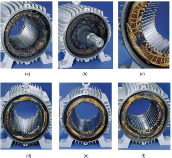
In the case of short circuits in the stator windings they are usually related to faults in the stator insulation system that cause turn-to-turn fault that initially remain undetected but later can progress to more serious short-circuits that can damage the machine [60]. Usually short-circuits occur between turns of one phase, or between turns of two phases, or between turns of all phases. The results produced by short circuits in the stator windings are presented in the Figure 2.5 and Figure 2.6.
Figure 2.5 - Typical insulation damage leading to inter-turn short circuit of the stator windings in
three-phase induction motors. (a) Inter-turn short circuits between turns of the same three-phase. (b) Winding short circuited. (c) Short circuits between winding and stator core at the end of the stator slot. (d) Short circuits
between winding and stator core in the middle of the stator slot. (e) Short circuit at the leads. (f) Short circuit between phases. [61]
According to Bonnett and Soukup [62] most failures that occur in the stator are related to thermal, electrical, mechanical and environmental stresses. The physical integrity of stator windings insulation system is critical to a correct motor operation. For such there are a set of insulation subsystems that have to be considered:
Between conductors of the same coil;
Between different phases;
Between the conductors and the slot where they are housed.
When the insulation system loses its physical integrity, it ceases to be resistant to stresses and occurs a situation of short circuit that later can lead to a failure situation. It is estimated that for every 10 ºC increase in the operating temperature of the windings, the lifetime of the insulation system is halved [62].
2.2.1.1
Causes for Stator Faults
Thermal Stresses
Thermal stresses are related with the incorrect use of the motor that will later cause an increase in temperature. Over time the insulating materials that constitute the insulation system are brittle and crack. These symptoms are related to the thermal stresses that causes expansion and contraction of these materials. Bonnett and Soukup [62] argue that this type of overloads can be caused by any of the following conditions:
Voltage Variations: Nowadays the induction motors are manufactured to support variations in the supply voltage of about 10%. The operation outside these limits will cause a decrease in the lifetime of the insulation system;
Unbalanced Phase Voltage: The existence of small unbalances in supply voltage causes an excessive increase in temperature of the windings and therefore in the insulation system. For each 3.5% unbalanced voltage per phase there is an increase of 25% in the temperature of the phase with the highest current value. The supply voltage must be kept as balanced as possible to avoid damages in the insulation system;
Repeated and/or consecutive starts: It is well known that during the startup, the stator currents are 3 to 6 times higher than the nominal current. So if the motor is subjected to multiple starts in a short period of time, the temperature of will increase and overheat the insulation system;
Overloading: There are situations where the total power is used, in this situation an increase in the load leads to an overload. It is estimated that the winding temperature rise will increase as the square of the load, which leads to a reduction in the lifetime of the insulation system;
Obstructed Ventilation: The motor should be kept clean inside and outside to ensure that the cooling system works correctly. Anything that restricts the flow of air will cause a temperature increase in stator and rotor components;
Figure 2.6 - Inter-turn short circuit of the stator winding in three-phase induction motors. (a) Short circuits in one phase due to motor overload (b) Short circuits in one phase due to blocked rotor. (c) Inter-turn short circuits are due to voltage transients. (d) Short circuits in one phase due to a phase loss in a Y-connected motor. (e) Short circuits in one phase due to a phase loss in a delta-connected motor. (f) Short circuits in
one phase due to an unbalanced stator voltage. [61]
Electrical Stresses
The insulation lifetime is directly related with the electric stresses applied in the motor. When the insulation system is exposed to additional electrical efforts, to ensure the electrical integrity of devices their lifetime decreases as the effort made by the material is higher. In the case of electrical machines is necessary to ensure a proper insulation to avoid damages in the windings. Electrical stresses are directly related to transient voltage regimes and the occurrence of partial discharges in the stator windings.
temperature. The consequences of these discharges result in heating, eroding or chemical reactions that causes the deterioration of winding insulation.
In [62] Bonnett and Soukup holds the view that the exposure of electrical motors to transient voltage condition causes a reduction in the lifetime of the windings and subsequently cause faults such as turn-to-turn or turn-to-ground short circuits. The existence of this type of transient voltages is related to a wide range of factors which are the following:
Supply overvoltage that sometimes reach 3,5 times their normal peak value in small ranges of time;
High voltage oscillations caused by bad connection to the ground;
Circuit breakers such as current limiting fuses that when interrupt the current in the circuit cause voltage oscillations;
Insulation failures can cause increases in the voltage that will exceed the normal operation voltages;
The use of capacitors connected to the stator windings to improve the power factor. When the capacitors and the motor are shutdown can cause magnetic resonance between the capacitors and the leakage inductances, resulting in transient regimes in stator windings;
The advent of variable frequency drives such as Pulse Width Modulation (PWM) drives
has simplified the motor control, but unfortunately it is known that the use of such equipments causes large electric efforts in the stator windings that lead to premature aging of the machine [64].
Mechanical and Environmental Stresses
There are a few mechanical and environmental problems that cause insulation degradation and therefore the appearance of stator faults. Theses stresses include coil movement resulting from vibrations, rotor strikes due to rotor unbalances and contaminations from foreign materials [62].
In the case of mechanical stresses, they are related with mechanical forces resulting from the current in the stator windings that produce a force on the coils which is proportional to the square of current. This force produces vibrations in the coils at twice the synchronous frequency which cause radial and tangential movement in the coils [62].
The presence of foreign material, such as dust, moisture, oils, and chemicals may have a contaminating and abrasive effect that result in a premature degradation of stator materials. In this type of stresses one of the most common is the phenomenon of condensation in the stator windings which leads to ground out in the slot. So to ensure a trouble-free engine operation is extremely important to keep the unit clean and dry, both internally and externally.
2.2.2
Rotor Faults
Currently there are two types of squirrel-cage rotor in induction machines: cast and fabricated (Figure 2.7). The cast rotors are usually used in small machines with low power and are almost impossible to repair in case of failure, due to the way they are manufactured, while the fabricated rotors are used in larger machines or specific applications and in case of failure there is the possibility of reparation.
Figure 2.7 –Two types of squirrel-cage rotors. (A) Cast rotor (B) Fabricated rotor
According to Nandi and Toliyat [56] rotor faults in this type of induction motors (squirrel-cage rotor) can be divided into two categories: broken rotor bars (Figure 2.8) and cracked end-rings. Although they are different faults they are both related because of their physical connection.
A broken rotor bar (BRB) or a cracked end-ring force the healthy bars to carry additional
current that leads to rotor core damage due to the elevated temperatures in the vicinity of the broken bars and the additional currents pass through the core from broken to healthy bars.
Figure 2.8 –Fabricated rotor of a 5 MW rated power (Pel) machine with multiple broken rotor bars [65]
2.2.2.1
Causes for Rotor Faults
Thermal Stresses
Any increase in temperature during motor operation can also cause thermal overload in the rotor. Generally thermal stresses appear during acceleration, running or stall conditions. Even with the modern protection systems that limits the temperature in the machine, the rotor does not remain free of damages because usually the protection systems are implemented in the stator side. There are numerous causes for the existence of thermal overloads, the most common are the following [62, 66]:
excessive consecutive starts that causes high temperatures in the rotor bars or end rings;
bearing failures and/or eccentricities in the air-gap that causes strikes between rotor and stator;
obstructed ventilation system;
unbalanced phase voltages;
broken rotor bars;
rotor stalling due to oscillations in the load.
Hot Spots and Excessive Losses
This type of thermal stress is caused by incorrect manufacture, design or repair processes that can cause unexpected losses and hot spots. In relation to the symptoms that cause hot spots and losses, these are mostly related to irregularities in the lamination of the rotor, such as, improper lamination design, variations in thickness and length of the blades. The only way to reduce these symptoms is through tests and repairs made after the manufacturing process [62, 66].
Rotor Sparking
Usually rotor sparking occurs in high power machines with fabricated rotor. There are several reasons for rotor sparking, some are not harmful to the rotor and others can cause failures. In the case of non-destructive sparks, they have low intensity and are rarely observed. These sparks are primarily related to voltage drops in the rotor, load fluctuations, switching disturbances that generally occur in full load or speed regimes. During the startup period, sometimes there is a period of intensive sparking due to high currents that exists during this operation period, but does
not present risks to machine’s safety.
The sparks that can cause destruction of some component in the rotor depends on several factors. However, broken bars and end-ring defects are the most common causes. Despite these sparks have great intensity compared with the non-destructive sparks are also difficult to observe [62, 66].
Magnetic Stresses
The electromagnetic forces generated by the slot linkage flux are unidirectional and proportional to the square of the rotor current. These forces cause a radial displacement of the rotor bars from the inside to the outside of the rotor as can be seen in Figure 2.9. A loose rotor bar can cause a strike against the stator winding causing a catastrophic motor failure.
Figure 2.9 –(A) Bar housed in a slot without damage (B) Bar housed in a slot with damage (adapted from
[68])
Besides electromagnetic forces, there are other magnetic stresses that affect the machine, for example the case of unbalanced magnetic pulls (UMP). Ideally an electric machine must have
the rotor centered in the air-gap, resulting in a balance of the magnetic forces that does not cause
deflection in the rotor. However, in a ―real‖ machine, the rotor is not centered in the air-gap due to situations such as eccentricities, belt loading, bearing wear and others that affect the position of the rotor in the air-gap.
According to [67] for these stresses, there is an area where the distance between the rotor and stator decreases and there will be another area where the distance between the rotor and stator will increase. The occurrence of changes in the air-gap also causes changes in magnetic reluctance, for example in the case where the distance between the rotor and stator decreases, the magnetic reluctance also decreases, unlike the magnetic force that increases and force the rotor to move in the direction where this attraction have more intensity, until the distance between the rotor and stator tends to zero, which means a strike between the rotor and stator.
Residual Stresses
Environmental Stresses
Like in the stator side environmental stresses also affect the rotor. The presence of chemicals, oils and dust can cause contamination and corrosion. These environmental stresses usually affect the ventilation system causing obstruction to airflow. Another consequence of this stress is the corrosion that can cause unbalanced weights in the rotor and consequently strikes between the rotor and stator.
2.3
Mechanical Faults
According to Table 2.1 and Figure 2.2 almost 40 to 45% of faults in inductions machines are related to mechanical faults. Zhongming and Bin [69] states there are two types of mechanical faults:
Bearing faults;
Air-gap eccentricity;
2.3.1
Bearing Faults
Bearing are common elements in rotating electrical machines. In fact, almost all the rotating electrical machines use either ball or rolling bearings to decrease friction between the motor frame and the shaft, which increase the machine efficiency. Motor bearings may cost between 3 and 10% of the actual cost of the motor, but the hidden costs involved in downtime and lost production combine to make bearing failure a rather expensive abnormality [70]. According to the EPRI report [58] and to the IEEE-IAS survey [57] faults in bearing elements represent the
most common cause of faults in induction machines.
An either-ball bearing is composed by two rings called inner and outer race rings (Figure 2.10). A set of balls or rolling elements are placed in raceways to rotate inside of these rings. There are several reasons that cause bearing faults, the most common are the following:
1. poor lubrication;
2. improper application or installation; 3. excessive vibrations;
4. shaft misalignments; 5. mechanical overload; 6. bearing currents;
Bearing faults can be categorized as outer bearing race defects, inner bearing race defects, ball defects and train defects. These faults result in rough running that generates detectable vibrations and increase noise levels [71]. The continuous operation of the machine in a bearing fault situation causes fragments of material to break loose that produce fatigue problems known as flaking and spalling [71].
Figure 2.10 –Schematic diagram of a rolling-element bearing [72]
2.3.2
Air-gap Eccentricity
Machine eccentricity is defined by Vas as an ―asymmetric air-gap that exists between the stator and rotor‖ [73]. When the rotor in not centre aligned with the stator core, the rotor stops to
describe a circular trajectory which causes a variation in the air-gap thickness. This phenomenon causes the appearance of unbalanced radial forces that lead to efforts in the stator windings and at worst case may cause strikes between rotor and stator, resulting in damages to both components [66]. There are two types of air-gap eccentricity (Figure 2.11) [67]:
1 Static eccentricity; 2 Dynamic eccentricity;
Figure 2.11 - Different types of eccentricity (border line is the stator inner ring, round rotor is in grey). (a)
Without eccentricity (b) Static eccentricity (c) Dynamic eccentricity (from [60])
23
Chapter 3
In this chapter the first sections presents some terminologies and definitions that are used in the FDD field. There are also classified the FDD methods that currently exists. Secondly, it is
made a survey on the different concepts of maintenance and its importance. Then, it is made a wide description of the methods that are currently used to detect and diagnose faults in induction machines.
3.1
Introduction
The industrial era, triggered by the industrial revolution in the eighteenth century generated an unprecedented economic growth in human history. The fact of existing large quantities of raw materials available, low cost of labor force and a continuous technological development, led mankind to believe that the paradigm of mass production, mass consumption would lead humanity to a period of exponential development and sophistication. This would not be verified due to several factors, such as shortage of raw materials, environmental problems, health problems that put in risk the human population and social problems that create more unemployment and differences between social classes.
Nowadays people and especially the companies besides the financial difficulties have to deal with labor, environmental and security problems. In the industrial field the first steps to increase the productivity, improve the robustness of processes and reduce the operation time were given through the use of machines, control systems and information technologies. These items can be clustered in a word, automation.
Automation is a significant component of modern engineering systems. Although automation brings several advantages, such as those described above, it also increases system complexity. According to [74], the increasing of the system complexity results in an overload of information and makes the system more susceptible to faults. The appearance of a fault in a process or in an industrial complex is something undesirable, system faults can lead to serious consequences, such as plant shutdown, huge economic loss, and human casualties. Therefore,
Fault
Detection
and
Diagnosis
in
along with automation, Fault Detection and Diagnosis (FDD) systems have an increasing interest
because it improves the reliability and availability of the system.
3.1.1
Terminology and Definitions
The terminology used in the field of FDD is not unique. Therefore, the used terminology
tries to follow the definitions proposed in the Safeprocess Technical Committee of IFAC
(International Federation of Automatic Control) and references such as Isermann and Ballé [75].
Fault: Unaccepted deviation of at least one characteristic property or parameter of
a system from its standard condition;
Failure: inability of a system or a component to accomplish its function;
Symptoms: A change of an observable quantity from its normal behavior;
Fault detection: indication that something is wrong in the monitored system;
Fault isolation: determination of the exact location, type, and time of the detected
fault. Usually fault isolation is confused with fault diagnosis;
Fault diagnosis: determination of the magnitude of the fault. Sometimes fault
diagnosis can include, fault detection and isolation;
Monitoring: Continuous (real-time) task of discovering the condition of a
component or system through data acquisition;
Reliability: probability of a system to perform a required function during a given
period of time in normal conditions;
3.1.2
Fault classification
As mentioned in the previous section, faults are events that can influence the behavior of various components of a system. Concerning to the faults location, these can happen in actuators, sensors and in internal components of a system.
The effects of a fault can also be classified in relation to the consequences produced over time. They can be divided in three categories, as can be seen in the Figure 3.1.
Figure 3.1 –Time-dependency of faults. (a) Abrupt fault (b) Intermittent fault (c) Incipient fault
because in an initial stage present a low severity index, but in a final stage may evolve into an abrupt fault. In this research work only incipient faults are considered.
3.1.3
Classification of the
FDD
methods
The types of methodologies used in fault detection and diagnosis are dependent of the process and the type of information available to be used for FDD purposes. Taking into account
the variety of existing processes in today’s industry, it is natural the existence of several methods for detection and diagnosis of faults. In the Figure 3.2 is represented how Isermann [76] classifies the existent fault detection methods.
Figure 3.2 – Fault detection methods classification [76]
Fault detection methods can also be classified in three different approaches: model-based, signal-based and data-based. In fact, all the mentioned approaches use signal processing but the way as signal processing is used is different and the impact in the final result is also different. Model-based methods are based on the use of analytical redundancy, for example is provided a theoretical model of the system and the difference between the measured data and the predicted values obtained from the theoretical model are used to detect fault situations (Figure 3.3).
Figure 3.3 - Schematic diagram of model-based methods
signals. The detection of faults in signal-based methods has two important stages. First it is necessary to recognize a deviation or a fault signature in the measured variables. This is called pattern recognition. The second stage is the decision-making, where it is classified the fault and his magnitude.
In data-based techniques the sampled data is used to extract a set of features that are clustered in order to classify them. This technique does not require any knowledge of machine parameters as Model-based or Signal-based techniques require. One form of a knowledge-based system is an expert system, which is defined by Biondo [77] as a ―computer program that uses knowledge, facts, and reasoning techniques to solve problems and make decisions.‖ The
schematic diagram of an expert system is shown in the Figure 3.4. The knowledge acquisition modules have the objective of acquiring new facts or rules from the human experts and specialists. The knowledge base is similar to a database where are stored all the facts and rules introduced by the humans. Regarding to the inference engine, this module is the manager of the knowledge base. In this module is processed the information provided by the knowledge base.
Figure 3.4 –Expert System structure (adapted from [77])
Concerning to diagnosis there are also numerous methods used currently. In Figure 3.5 is the division proposed by Isermann [76].
3.1.4
Maintenance
Since the principles of mankind the human being felt the need to keep his equipment in good conditions. No matter how the equipments are designed, to keep them operating at desired reliability level, maintenance is required. According to Tsang et al. [78] maintenance is the act of
repairing broken items.
Maintenance of electrical machines is a very popular topic, since it corresponds with industrial requests for an increasing number of applications where reliability is a keyword. It is known that an interruption in a manufacturing process causes loss of funds to a company, so a proper maintenance and an early detection of faults can result in a reduction of financial losses.
In the literature the maintenance methods are presented by different authors in different perspectives. However, the most important is to realize that maintenance methods refer to the way the maintenance tasks are planned and scheduled. According to Tavner et al. [3] there are three
basic maintenance strategies that have to be considered:
Breakdown maintenance;
Planned maintenance;
Predictive maintenance.
In breakdown maintenance (BM) the problems are only fixed when they occur. This type
of maintenance is used when the equipment does not have significant importance to the operation or does not generate significant losses. A planned maintenance (PM) consists in periodic
inspections to replace parts that are supposed to break after a certain number of hours. A predictive maintenance (PdM) or condition-based maintenance (CBM) consists in the evaluation
of the equipment condition by performing periodic (off-line) or continuous (on-line) analysis of the device status. The main advantages and disadvantages of these three types of maintenance are presented in the Table 3.1.
Type of Maintenance Advantages Disadvantages
Breakdown Maintenance (BM)
No over-maintenance;
Minimal management;
Requires fewer staff;
Large spare inventory;
High cost repairs;
Intensive labor;
Safety problems;
Type of Maintenance Advantages Disadvantages
Preventive Maintenance (PM)
Increased component life cycle;
Reduced unexpected failure;
Decreased system downtime;
Unneeded maintenance;
Catastrophic failures still likely to occur;
Condition-Based Maintenance (CBM)
Improved usage efficiency and reliability of the equipment;
Decrease in costs for parts and labor;
Reduced unplanned downtimes;
Increased investment in staff training;
Increased investment in diagnostic equipment;
Table 3.1 –Comparison of maintenance techniques
There are other two techniques of maintenance that are not referred by Tavner et al., the
reliability-centered maintenance (RCM) and E-Maintenance. The concept of RCM was firstly used
in the 1970s in the aviation industry and later was used in nuclear plants [79]. Moubray [80] refers to reliability-centered maintenance as a process to establish the safe minimum levels of maintenance. According to [79] RCM is a strategy used to determine cost-optimized maintenance
point that is needed to sustain the operational reliability of systems and equipment.
In RCM there are criteria used to distinguish which are critical components in the system.
In the case of critical components, planned maintenance actions are performed in order to prevent a decrease in reliability or deterioration in safety levels. For non-critical components, the
components are left to ―run to failure‖ (BM). The component is replaced only when it ceases to
fulfill its function. These corrective actions are only applied to low cost components that do not represent safety problems to the system.
RCM depends on the same measurements used in CBM, but saves additional maintenance
resources by spending less effort on less important machinery. RCM also requires more training
and software than CBM.
![Figure 3.12 - Equipment used to measure the axial flux in an electrical machine [97]](https://thumb-eu.123doks.com/thumbv2/123dok_br/16580703.738537/63.892.262.659.338.601/figure-equipment-used-measure-axial-flux-electrical-machine.webp)