Sara Alves de Melo Jerónimo
Licenciada em Ciências da Engenharia CivilHygrothermal Behaviour of Insulated
Rammed Earth Walls
Dissertação para obtenção do Grau de Mestre em Engenharia Civil – Perfil de Construção
Orientador: Fionn McGregor, Investigador, École National des Travaux Publics de l’État, Lyon
Co-orientador: Paulina Faria, Professora Associada,
Faculdade de Ciências e Tecnologia da Universidade Nova de Lisboa
Júri:
Presidente: Prof. Doutor Mário Vicente da Silva Arguente: Prof. Doutor Daniel Aelenei
Vogal: Doutor Fionn McGregor
© Copyright Sara Alves de Melo Jerónimo, da FCT/UNL e da UNL
I
Acknowledgements
I would like to express my gratitude to Professor Paulina Faria that enabled this amazing experience
to happen and for her concern shown during these six months.
I am deeply grateful to Dr. Fionn McGregor for all he taught me, for his availability, kindness and
the invitation to continue this work in Lyon. In addition, I would like to thank Dr. Antonin Fabbri and
Joachim Blanc-Gonnet and all the ENTPE team who always helped me. I would also like to thank ENTPE
for the great welcome, financial support and availability to acquire all the material essential for my work.
This experience allowed me to grow up not only intellectually, but also as a person. I have dealt with
so many challenges, a new language and customs. I met wonderful people from all over the world and
learned so much with them. I loved to discover a new city with such rich culture and designed to benefit
the citizens.
Therefore, I would like to thank my best friend Inês Costa that made part of this adventure and shared
with me all these cheerful days (and not so good ones too). I am also thankful to my friends that have been
part throughout the whole graduation and always kept me in touch and visited me.
I am grateful to my parents and sister, for always encouraging me to move out of my comfort zone
and to enjoy meeting new places.
Finally, I would like to thankmy boyfriend, Pedro Marreiro, who, even though being apart was so
III
Abstract
Rammed earth is an ancient construction technique for monolithic walls which consists in compacting
raw earth in successive layers inside a formwork. The properties of the earth contribute to improve indoor
comfort, acting as a buffer to relative humidity levels and internal temperature variations. Moreover, it
has a low incorporated energy and it can be reused, contributing to a sustainable building industry.
However, earth walls have a low thermal resistance when compared with other solutions used
nowadays, which in some regions makes it necessary to add further insulation. The sensitivity of earth
wall to moisture content requires the added insulation material to be sufficiently vapour permeable to
allow the necessary moisture regulation of the wall.
This dissertation aim is to measure in laboratory the behaviour of a rammed earth wall placed into a
climatic chamber. In this regard, sensors measuring the temperature, relative humidity, heat flux and water
content in different locations of the climatic chamber were introduced. The wall behaviour was monitored
without any insulation and was then combined with two types of insulation materials: a synthetic and
waterproof insulation board (polystyrene) and a bio-based plaster insulation (hemp-lime), both applied on
the interior surface of the wall. The tests consisted in 8h cycles of defined temperature and relative
humidity.
The obtained results confirmed that rammed earth walls present high thermal inertia properties. With
the addition of a polystyrene insulation on the interior surface, the wall is no longer able to release heat
when the interior temperature drops, as polystyrene acts as a barrier and the vapour exchange is blocked.
The hemp-lime plaster was added with the objective to include an insulation adequate to the vapour
permeability requirements of the rammed earth wall. Due to the slow drying process of this particular
insulation -with ~11% /month of relative humidity decrease- both the wall and insulation hygrothermal
behaviours were not submitted to tests, being this left as future work.
Keywords: Monolithic wall; Rammed earth; Hygrothermal behaviour; Polystyrene insulation;
V
Resumo
A taipa é uma técnica de construção antiga que consiste na compactação de terra crua por camadas
dentro de uma cofragem que se designa tradicionalmente por taipal, constituindo paredes monolíticas. As
propriedades da terra contribuem para melhorar o conforto no interior das habitações, atuando como
estabilizadora dos níveis de humidade relativa e proporcionando uma grande inércia térmica. Para além
disso, ainda é ambientalmente sustentável pois é um material reutilizável que permite construir edifícios
com baixa energia incorporada.
Em comparação com técnicas construtivas atualmente utilizadas, as paredes de taipa têm uma menor
resistência térmica o que obriga a que, em certas regiões, funcionem em conjunto com isolamento térmico
para obter resultados equiparáveis. A alta permeabilidade ao vapor de água de uma parede de taipa requer
que o isolamento adicionado apresente características semelhantes, para o seu bom funcionamento.
O objetivo desta dissertação é estudar o comportamento de uma parede de taipa dentro de uma câmara
climática, através de medições realizadas em laboratório. Para tal, foram inseridos sensores em ambos os
lados da parede e ao longo da sua espessura, medindo grandezas como a temperatura, humidade relativa,
fluxo de calor e teor de água. Inicialmente, o comportamento da parede foi monitorizado sem nenhum
isolamento; posteriormente a parede foi estudada em conjunto com dois tipos de isolamento distintos
colocados na sua face interior: um isolamento sintético e à prova de água (poliestireno), e um isolamento
natural sob a forma de um reboco de cânhamo e cal. A parede foi sujeita a ciclos de 8h de temperatura e
humidade relativa definidas.
Os resultados obtidos mostraram a capacidade da parede de taipa de reter calor e libertá-lo
posteriormente. Com a colocação do isolamento de poliestireno, a parede deixou de ser capaz de reter
energia calorífica e transferi-la na forma de calor para o ambiente interior, quando a temperatura deste
baixou. Também as trocas de humidade entre a parede e o ambiente interior foram impedidas.
A fim de testar um isolamento com os requisitos de permeabilidade ao vapor de água semelhantes
aos da taipa, foi adicionado um reboco de cânhamo e cal. Devido ao seu lento processo de secagem –
decréscimo de humidade relativa de ~11%/mês - não foi possível estudar o seu comportamento
higrotérmico, sendo apresentado para trabalho futuro.
Palavras-Chave: Parede monolítica, Taipa, Comportamento higrotérmico; Isolamento poliestireno,
VII
Notations and Symbols
A Water absorption coefficient [kg/(m2.s1/2)]
A Area [m2]
a Thermal diffusivity [m2/s]
C
C
Specific heat [J/(kg⋅K)]
Mean curvature [m-1]
CP Heat capacity at constant pressure [J/(kg.K)]
D Diffusivity [m2/s]
DF Decrement factor [-]
E Effusivity [J/(kg.m2.s-2)]
e Thickness of the material or the layer [m]
ℎ𝑐 Convective surface film coefficient [W/(m2.K)]
HF_ext Heat flux on external surface of rammed earth wall [W/m2]
HF_ins Heat flux on insulation surface [W/m2]
HF_int Heat flux on internal surface of rammed earth wall [W/m2]
HF_int_s Heat flux on internal surface of rammed earth wall measured with a small heat flux meter [W/m2]
J Diffusion flux [mol/(m2.s)]
K Intrinsic permeability of the porous medium [m2]
L Latent heat [J/kg]
p Equilibrium pressure [Pa]
𝑀𝐻2𝑂 Molar mass of water molecules [g/mol]
𝑝𝑎𝑡𝑚 Atmospheric pressure [Pa]
𝑝𝐿 Liquid pressure [Pa]
𝑝𝑣 Water vapour partial pressure [Pa]
𝑝𝑣𝑠𝑎𝑡 Saturated vapour pressure [Pa]
Q Amount of heat energy [W]
q’ Internal heat generation [W/m3]
R Perfect molar gas constant [J/(mol.K)]
RH Relative humidity [%]
RH_bonduary Relative humidity measured on the exterior edge of insulation [%]
RH_control_int Relative humidity which controls the heater and humidifier devices [%]
RH_ext Relative humidity measured on external side ambient of the chamber [%]
VIII
RH_ref_air Relative humidity outside the chamber [%]
RH_wall Relative humidity measured in the middle of rammed earth wall [%]
RH_wall_10cm Relative humidity measured 10 cm from the interior surface of rammed earth wall [%]
RH_wall_ins Relative humidity measured between rammed earth wall and insulation [%]
𝑅𝑠𝑖 Internal surface thermal resistance [(m².ºC)/W]
𝑅𝑠𝑒 External surface thermal resistance [(m².ºC)/W]
𝑅𝑣𝑎𝑙𝑢𝑒 Thermal resistance [(m².ºC)/W]
r Capillary radius [m]
S Sensitivity [V/(W/m) 2]
𝑆𝑟 Water saturation ratio [-]
t Time [s]
T Temperature [K]
𝑇0 Reference temperature [K]
T_bonduary Temperature measured on the exterior edge of insulation [ºC]
T_control_int Temperature which controls the heater and humidifier devices [ºC]
T_ref_air Temperature outside the chamber [ºC]
T_wall Temperature measured in the middle of rammed earth wall [ºC]
T_wall_10cm Temperature measured 10 cm from the interior surface of rammed earth wall [ºC]
T_wall_ins Temperature measured between rammed earth wall and insulation [ºC]
Ta_ext Ambient temperature measured on external side of the chamber [ºC]
Ta_int Ambient temperature measured on internal side of the chamber [ºC]
Ts_ext Surface temperature of the wall measured on external side of the chamber [ºC]
Ts_int Surface temperature of the wall measured on internal side of the chamber [ºC]
TL Time lag [h]
U Voltage [V]
𝑈𝑣𝑎𝑙𝑢𝑒 Thermal conductance [W/(m2.ºC)]
V Volume [m3]
Vw_wall Water content in the middle of rammed earth wall [%]
w Water content [kg/m3]
IX
∝ Heat transfer coefficient [W/(m2.K)]
𝛽 Water vapour transfer coefficient [kg/(m2.s.Pa)]
𝛿𝑎 Permeability of the air into water vapour [kg/m.s.Pa]
𝜀 Emissivity of the material [-]
𝜂𝐿 Dynamic viscosity of water [Pa/s]
𝜙 Porosity [-]
𝜙𝐿 Porosity filled by the liquid phase [-]
𝜃 Contact angle formed by the liquid/vapour interface [º]
𝑘 Intrinsic permeability of the porous medium [m2]
𝑘𝑟𝐿 Relative liquid permeability [-]
λ Thermal conductivity [W/(m.°C)]
𝜇 Water vapour diffusion coefficient
𝜌 Dry density [kg/m3]
𝜌𝑑 Density of the dried earth material [kg.m-3]
𝜌𝐿 Liquid water density [kg.m-3]
𝜎 Surface tension [N/m]
𝜎0 Stefan-Boltzmann constant [W/(m2.K4)]
Φ Heat flux [W/m2]
XI
Contents
Acknowledgements ... I
Abstract ... III
Resumo ... V
Notations and Symbols ...VII
Contents ... XI
List of Figures ... XIII
List of Tables ... XV
1. Introduction ... 1
1.1.Context ... 1
1.2.Objective and Methodology ... 2
1.3.Dissertation Structure ... 3
2. Heat Transfer and Hygrothermal Behaviour ... 5
2.1.Heat Transfer ... 5
Conduction ... 5
Convection... 6
Radiation ... 6
2.2.Moisture Behaviour of Building Materials ... 7
2.2.1. Moisture Sorption and Storage ... 7
2.2.2. Vapour Transfer ... 9
2.2.3. Moisture Transport ... 12
2.3.Thermal Behaviour of Building Materials ... 13
2.3.1. Thermal Transmittance ... 13
2.3.2. Thermal Inertia ... 14
2.3.3. Diffusivity and Effusivity ... 15
2.4.Hygrothermal Behaviour ... 15
3. Materials and Methods ... 19
3.1.General Remarks ... 19
3.2.Materials ... 19
3.3.Tests Procedure ... 21
3.4.Sensors and Data Acquisitions ... 26
3.4.1. Constructive Solution 1 – Without Insulation ... 26
3.4.2. Constructive Solution 2 – Chamber with Insulation ... 29
3.4.3. Constructive Solution 3 – Rammed Earth with Polystyrene Insulation ... 31
3.4.4. Constructive Solution 4 – Rammed Earth with Hemp Insulation ... 31
XII
4. Results and Discussion ... 33
4.1.Preliminary Remarks ... 33
4.2.Constructive Solution 1 – Without Insulation ... 33
4.2.1. Outside Variation ... 33
4.2.2. Analysis of the Chamber Efficiency ... 34
4.2.3. Theoretical Formulas and Sensor’s Data ... 37
4.3.Constructive Solution 2 - Chamber with Insulation ... 39
4.3.1. RH Cycles... 39
4.3.2. T Cycles Against RH Cycles ... 40
4.4.Constructive Solution 3 - Rammed Earth with Polystyrene Insulation ... 41
4.5.Constructive Solution 4 - Rammed Earth with Hemp Insulation ... 43
4.6.Comparison Between Constructive Solutions ... 45
4.6.1. Heat Storage Capacity ... 45
4.6.2. Thermal Inertia ... 47
4.6.3. Time Lag ... 48
4.6.4. Water Content ... 50
4.6.5. Moisture Buffering ... 51
4.6.6. Water Vapour Penetration ... 52
5. Conclusion ... 55
5.1.Final Conclusions ... 55
5.2.Proposals for Future Work ... 57
References ... 59
Appendix ... A.1
I – Sensors Location – Side View ... A.1
II – Constructive solutions results... A.3
A.1. Constructive Solution 1 – Outside Variation ...A.3
A.2. Constructive Solution 1 – T constant ...A.4
A.3. Constructive Solution 1 – T cycle ...A.5
B.1. Constructive Solution 2 – T cycle ...A.6
B.2. Constructive Solution 2 – RH cycle ...A.7
B.3. Constructive Solution 2 – T & RH cycle ...A.8
C.1. Constructive Solution 3 – T constant ...A.9
C.2. Constructive Solution 3 – T cycle ...A.10
C.3. Constructive Solution 3 – RH cycle ...A.11
XIII
List of Figures
Figure 2.1 - Representation of the porous medium and their interactions (based on Fabbri, 2017) ... 8
Figure 2.2 – Diagram of moisture storage (Künzel, 1995) ... 8
Figure 2.3 - Psychrometric chart (Willis Carrier, 1975) ... 10
Figure 2.4 - Hysteresis in mineral materials (adapted from Henriques, 2011) ... 11
Figure 2.5 - Sorption isotherm (Hens, 2012) ... 11
Figure 2.6 - Saturation from Kelvin law at 20ºC (adapted from Henriques, 2011) ... 12
Figure 2.7 - Hygrothermal coupling (based on Soudani, 2016) ... 16
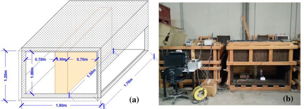
Figure 3.1 - Design of the climatic chamber (a) and the real climatic chamber (b) ... 19
Figure 3.2 – Chamber location in the laboratory ... 20
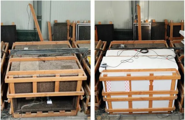
Figure 3.3 - Improvements in chamber: constructive solution 1 (a) and constructive solution 2, 3 and 4 (b) ... 22
Figure 3.4 - Improvements in rammed earth wall: constructive solution 1 (a), constructive solution 2 (b), constructive solution 3 (c) and constructive solution 4 (d)... 23
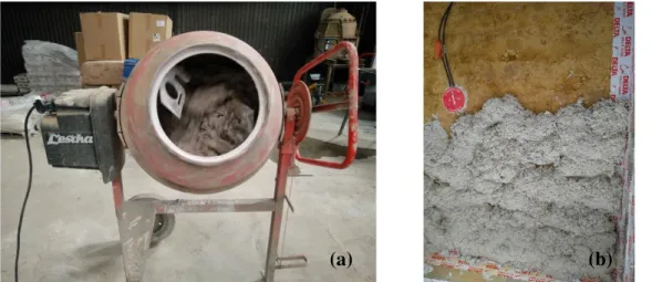
Figure 3.5 – Preparation (a) and aplication (b) of hemp-lime plaster ... 24
Figure 3.6 – Hemp-lime sample (a) and thermal conductivity determination (b) ... 24
Figure 3.7 - Representation of T and RH cycles for each constructive solution ... 25
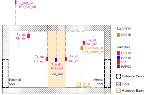
Figure 3.8 - Sensors location in constructive solution 1 - side view ... 27
Figure 3.9 - Sensors location in constructive solution 1 - Upper view ... 27
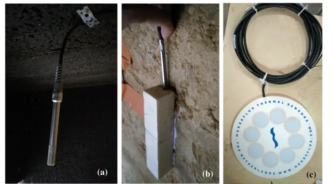
Figure 3.10 - CS215 sensor (a), 107 Temperature Probe sensor (b) and HFP03 sensor (c) ... 28
Figure 3.11 – Heat flux positive direction ... 28
Figure 3.12 - Heat flux plates: HFP01SC (left) and HFP03 (right) ... 30
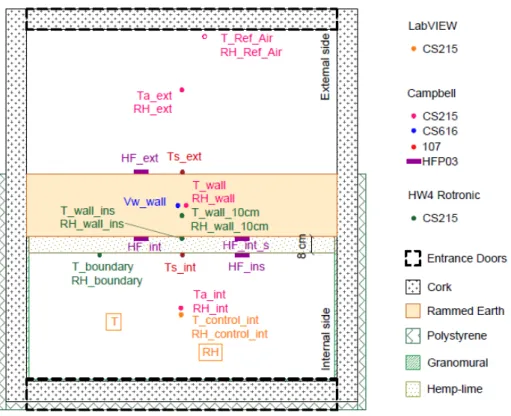
Figure 3.13 - Sensors location in constructive solution 2 - Upper view ... 30
Figure 3.14 - Sensors location in constructive solution 3 - Upper view ... 31
Figure 3.15 - Sensors location in constructive solution 4 - Upper view ... 32
Figure 3.16 - Infrared camera analysing the chamber ... 32
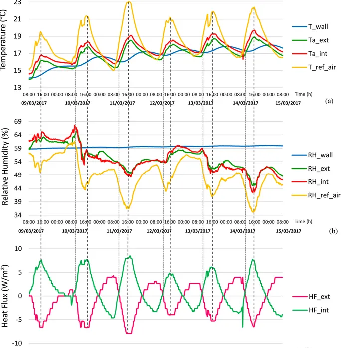
Figure 4.1 – Comparison between T (a), RH (b) and heat flux (c) variations during constructive solution 1. ... 34
Figure 4.2 - Infrared thermography ... 35
Figure 4.3 - Infrared thermograpy with ventilation (a), junctions between cork boards (b) ... 35
Figure 4.4 - Infrared thermography with ventilation - Upper view ... 36
Figure 4.5 – T constant in constructive solution 1 ... 36
Figure 4.6 – Average temperature profile assuming quasi-steady state conditions ... 37
Figure 4.7 - Comparison between theoretical formulas and sensor’s data (CS1 – T cte) ... 38
Figure 4.8 – RH cycles in constructive solution 2 ... 39
Figure 4.9 – Inconsistence between RH_int and RH_control_int ... 40
XIV
Figure 4.11 - Infrared thermography with polystyrene - Upper view ... 42
Figure 4.12 – T along the insulated wall ... 42
Figure 4.13 – Drying cycle of hemp-lime plaster ... 44
Figure 4.14 – Water content in the middle of the rammed earth wall ... 44
Figure 4.15 – Drying cycle of hemp-lime plaster ... 45
Figure 4.16 – T profile for each constructive solution ... 46
Figure 4.17 - Heat flux in constructive solution 3 ... 47
Figure 4.18 – Thermal inertia of the wall without and with polystyrene ... 47
Figure 4.19 – Time lag in every constructive solutions ... 49
Figure 4.20 – Relation between T inside the wall (a) and water content (b) ... 50
Figure 4.21 – Moisture behaviour of the wall without (a) and with (b) polystyrene insulation ... 52
Figure A. 1 - Sensors location in constructive solution 2 - side view ...A.1
Figure A. 2 - Sensors location in constructive solution 3 - side view ...A.1
Figure A. 3 - Sensors location in constructive solution 4 - side view ...A.2
Figure A. 4 – Constructive Solution 1 – Outside variation: (a) Temperature variation; (b) Surface
temperature variation (c) Relative humidity variation; (d) Heat Flux variation; from 09/03 to 15/03 ....A.3
Figure A. 5 – Constructive Solution 1 – T constant: (a) Temperature variation; (b) Surface temperature
variation (c) Relative humidity variation; (d) Heat Flux variation; from 09/03 to 15/03 ...A.4
Figure A. 6 - Constructive Solution 1 – T cycle: (a) Temperature variation; (b) Surface temperature
variation (c) Relative humidity variation; (d) Heat Flux variation; from 09/03 to 15/03 ...A.5
Figure A. 7 – Constructive Solution 2 – T cycle: (a) Temperature variation; (b) Surface temperature
variation (c) Relative humidity variation; (d) Heat Flux variation; from 09/03 to 15/03 ...A.6
Figure A. 8 – Constructive Solution 2 – RH cycle: (a) Temperature variation; (b) Surface temperature
variation (c) Relative humidity variation; (d) Heat Flux variation; from 09/03 to 15/03 ...A.7
Figure A. 9 – Constructive Solution 2 – T constant: (a) Temperature variation; (b) Surface temperature
variation (c) Relative humidity variation; (d) Heat Flux variation; from 09/03 to 15/03 ...A.8
Figure A. 10 – Constructive Solution 3 – T constant: (a) Temperature variation; (b) Surface temperature
variation (c) Relative humidity variation; (d) Heat Flux variation; from 09/03 to 15/03 ...A.9
Figure A. 11 – Constructive Solution 3 – T cycle: (a) Temperature variation; (b) Surface temperature
variation (c) Relative humidity variation; (d) Heat Flux variation; from 09/03 to 15/03 ...A.10
Figure A. 12– Constructive Solution 3 – RH cycle: (a) Temperature variation; (b) Surface temperature
variation (c) Relative humidity variation; (d) Heat Flux variation; from 09/03 to 15/03 ...A.11
Figure A. 13 – Constructive Solution 3 – T & RH cycle: (a) Temperature variation; (b) Surface
XV
List of Tables
Table 3.1 – Materials properties ... 21
Table 4.1 – Time lag of temperature buffering ... 43
1. Introduction
1
1.
Introduction
1.1.
Context
Low environmental impact is an increasing concern in building design. For this reason, the use of raw
earth materials available on the construction site that need low energy for preparation have been
continuously tested.
The main benefit of earth lies with the fact that this material can be easily sourced locally and does not
require industrial processing (Morel, J. et al., 2001). If no stabiliser is added to the raw earth, it can be
infinitely reused, thus it has very low impact in terms of embodied energy when used as building material
in construction (Habert, G. et al., 2012).
Rammed earth is an ancient earth construction technique that can be currently found spread all over
the world. It is one of the most recent earth techniques, compared to others (adobe, cob, …). It was identified
for the first time in Carthage, Tunisia, founded around 814 BC (Jaquin, 2012). In the 8th century, rammed
earth reached Europe and it is very commonly used in the region of Rhône-Alpes, France, and in Alentejo,
Portugal, until nowadays. This technique consists in compacting local raw earth with a rammer in successive
layers, one after another, inside a removable formwork. The earth is composed of aggregates such as clay,
silt, sand and gravel, with the clay matrix as the binder of larger aggregates.
Stabilized rammed earth consists in introducing a binder component as additive that enhances the
cohesion of earth (Hall, 2007). Air lime was used for stabilization. In Portugal, the so called military
rammed earth (taipa militar) can be found in several fortresses from the period of Muslim occupation of
Iberian Peninsula. In modern times, Portland cement or lime are used as a stabiliser with proportions that
do not exceed 10% of total dry mass (Hall & Allinson, 2009).
Besides being environmental friendly in terms of materials, the rammed earth walls have a performance
that contributes to improve hygrothermal and acoustic indoor comfort. The porous material acts as a buffer
to relative humidity (RH) levels and internal temperature (T) variations (Taylor & Luther, 2004). The
material behaves adsorbing the moisture in excess and releasing during low moisture phases (McGregor et
al., 2016).
It was proved that the control of the indoor humidity environment benefits the inhabitants health
(Soudani et al., 2017), can help to improve the durability of the building envelope and the design of building
ventilation, provides thermal comfort and therefore reduces the energy consumption (Zhang & Yoshino,
2010), (Ramos, 2007).
In terms of health, high values of RH (> 75%) lead to the development of unwanted moulds causing
respiratory discomfort and allergies (Bornehag et al., 2001). On the other hand, exposure to low values of
RH (< 30%) for an extended period of time, may affect the mucous membrane and it is related to dryness
2
By reducing the frequency of high humidity periods at the wall surface, the rammed earth walls were
judged to be highly beneficial in reducing mould growth in buildings (Allinson & Hall, 2010).
The affinity of raw earth for water molecules confers cohesion to the material, through suction effects.
This affinity allows buffering RH variations and increases the thermal inertia of the wall, bringing quality
to interior comfort in terms of acoustic, hygric and thermic aspects (Chabriac et al., 2014).
Liquid water content of a rammed earth wall is an essential parameter to understand the behaviour and
the strength of this material (Chabriac et al., 2014). With the water content increasing, the strength of
unstabilised earth materials decreases (Champiré et al., 2016; Morel et al., 2007).
Rammed earth walls have a lower thermal resistance (R-value) than common solutions with insulations
such as polystyrene and polyurethane, even when insulated with natural wood fibres (Serrano et al., 2016),
which induce them to provide inferior performance in terms of insulation, although, with the best dynamic
performance and the longest thermal lags.
Rammed earth walls usually present a large thickness, between 30 and 50 cm, since the reduction of
their thickness heavily penalizes its thermal behaviour (Taylor, et al., 2008). In addition, thinner samples
are more affected by the surface film resistance (McGregor et al. 2017). Their thermal conductivity (~0.6
W/m.K) makes it necessary to add further insulation in most rehabilitation cases. The sensitivity of earth
wall to moisture content requires the added insulation material to be sufficiently vapour permeable to allow
the necessary moisture regulation of the wall.
1.2.
Objective and Methodology
The aim of this work is to study the performance of a construction material with low embodied energy
such as rammed earth, and compare its efficiency when an insulation is applied on its internal surface. In
this regard, one of the most industrial materials used nowadays (polystyrene) is submitted to several tests.
Afterwards, the same tests are made and therefore, compared with a bio-based insulation material
(hemp-lime plaster). For this purpose, the thermal and hygroscopic performance of an earth-based wall inside a
test chamber is monitored.
The objectives are to understand the heat and mass transfer within the rammed earth wall and the
impact of the addition of insulating material on the behaviour of the wall. Specifically, the behaviour at the
interface between the insulation and the rammed earth will be monitored.
A numerical simulation based on the material properties and classical hygrothermal model is made
using COMSOL Multiphysics, giving valuable information about the heat and vapour penetration in
1. Introduction
3
1.3.
Dissertation Structure
The present dissertation begins with a literature review given in chapter 2. Earth materials have a
special behaviour due to its hygroscopic characteristics and to make a proper study, a preliminary
knowledge is required. The relation between the rammed earth and the environment was studied: the
mechanisms of heat transfer, the moisture behaviour, the thermal behaviour and therefore the hygrothermal
behaviour of constructions made with rammed earth.
The chapter 3 defines the earth composition of the studied rammed earth wall and also the composition
of the two insulations applied on its internal surface. The type of sensors used in this work are defined as
well as its location along the wall. In the same chapter it is also presented the procedure that submitted the
wall to several tests where T and RH were the variables. An analysis of the climatic chamber efficiency was
made appealing to an infrared thermography.
Afterwards, in chapter 4, an analysis on the experimental procedures results was made. Primarily, each
constructive solution results were studied separately, and then, all solutions were compared in terms of its
heat storage capacity, time lag, moisture buffering and thermal inertia.
2. Heat Transfers and Hygrothermal Behaviour
5
2.
Heat Transfer and Hygrothermal Behaviour
This second chapter intends to explain the heat and moisture phenomena that occur in or across the
walls of hygroscopic materials such as rammed earth. It starts with heat transfer, moisture behaviour,
thermal behaviour and finally, it makes the link between these aspects and the hygrothermal behaviour.
2.1.
Heat Transfer
In buildings physics, there is an interest for the heat flux in systems that are not in equilibrium. The
basic condition for heat transfer to happen in a wall is the existence of a gradient of T between two surfaces
of the wall. This heat flux goes from the high temperatures to low temperatures and it ends when the
equilibrium between the two temperatures is reached.
The amount of heat transfer, Q, through a given surface, per unit time, ∆t, is called heat flux, Φ. The
heat flux density, q, presented in (1), is the heat rate per unit area, A, measured in W/m2.
𝑞 = 𝑄
𝐴 (1)
There are three mechanisms of heat transfer: conduction, convection and radiation, further explained
below in the next section.
Conduction
The heat transfer in a material is stated by the general equation of heat diffusion, equation (2).
𝜕 𝜕𝑥 (𝜆
𝜕𝑇 𝜕𝑥) +
𝜕 𝜕𝑦 (𝜆
𝜕𝑇 𝜕𝑦) +
𝜕 𝜕𝑧 (𝜆
𝜕𝑇
𝜕𝑧) + 𝑞′ = 𝜌𝑐𝑝 𝜕𝑇
𝜕𝑡 (2)
This equation describes real conditions, which means that it is in function of time, t. It also depends on
𝜌, which is the dry density [kg/m3] and 𝐶
𝑝, that is the heat capacity at constant pressure [J/(kg.K)]. In
addition, q’ is the internal heat generation and 𝜆 is the thermal conductivity of the material.
Specific heat capacity, CP, is the amount of energy required to raise 1ºC the T of 1 kg of a material, and
is usually expressed in J/(kg.K). In situ measurements made by Chabriac (2014) provide the heat capacity
value of the used rammed earth as CP = 647 J/(kg⋅K).
The conduction of heat energy happens by physical contact between solids at different temperatures
and between points at different temperatures in the same solid. The mode also works for liquids, gases and
between phases. The energy is spread when vibrating atoms collide and free electrons move collectively.
6
For steady-state unidirectional heat conduction, the Fourier law is:
Equation (3) states that the heat flux in the x direction, 𝑞𝑥, is directly proportional to the temperature
gradient 𝑑𝑡/𝑑𝑥. It is expressed in [W/m2]. 𝜆 in [W/m.ºC] represents the thermal conductivity of the material.
The heat flux is the quantity of heat that passes through the thickness of the material, per unit area. The
negative sign means that heat flux is positive in the direction of decreasing temperature. This equation
shows that the energy kept in one construction element, like a wall, depends on the density of that element,
the specific heat, the volume of the element and the thermal conductivity (Henriques, 2011).
Thermal conductivity, 𝜆, is a material property to conduct heat. It can be defined as the quantity of heat
transmitted through a unit thickness of a material per unit area due to T gradient and it is measured in
W/(m.ºC). Lower values of thermal conductivity lead to better thermal insulation. For simplicity reasons,
this property is assumed constant and scalar. Thermal conductivity is a function of T, moisture content,
thickness and sometimes age.
Convection
Convection is the principal form of heat transfer in liquids and gases. The T variation in fluids leads to
position change of the mass and variation in density. This results in convection currents, where the hotter
fluid comes up and the cold one goes down. It only happens in fluids given that there is no possible variation
of volume in solids.
Newton’s law of cooling gives the relation of the heat flux by convection between the surface at temperature 𝑇1 and the environment with the temperature 𝑇2, presented in equation (4).
𝑞𝑐𝑜𝑛𝑣= ℎ𝑐(𝑇1− 𝑇2) (4)
𝑞𝑐𝑜𝑛𝑣is the heat quantity and ℎ𝑐 is the convective surface film coefficient [W/(m2.K)]. The latter
depends of the geometry of the surface, the fluid nature and the type of movement (natural or forced
convection). The natural convection means that the movements of the fluid are done due to the T gradient,
whereas the forced convection happens when there is another source creating fluid movement, like a fan,
for example.
Radiation
Radiation is the transfer of energy that results from the emission and absorption of electromagnetic
waves without any medium to transport the heat. Above 0 K, each surface emits electromagnetic energy.
Between surfaces at different temperatures, the emission results in heat exchanges.
Although the impact of solar radiation is an important element in building materials experiences, it is
not going to be mentioned in this work because, during the experience that will be presented, the climatic
2. Heat Transfers and Hygrothermal Behaviour
7
chamber was placed inside a laboratory building. So, the only radiation considered is between the surfaces
of the rammed earth wall and cork used to insulate the chamber at different T.
The value of the radiated energy for a body, Q [W], with a certain absolute temperature, T [K], of a
material, follows the Stefan-Boltzmann equation, presented in equation (5).
𝑄 = 𝜎0. 𝜀. 𝐴. 𝑇4 (5)
In this equation the 𝜎0 is known as Stefan-Boltzmann constant, equal to 5,67×10⁻⁸ W/(m2.K4), 𝜀 is the
emissivity of the material, dimensionless, and A is the area [m2].
The emissivity is the capability of a surface to retransmit the heat that was already absorbed by
radiation. It is also the coefficient that links the energy emitted by one surface and the maximum amount
that a perfect black body can emit at the same T. The maximum value of the emissivity is 1.
2.2.
Moisture Behaviour of Building Materials
2.2.1. Moisture Sorption and Storage
Rammed earth is considered a hygroscopic material which means that its water content changes with
the variation of the RH in the surrounding environment, along with interstitial condensation and rain
absorption.
Water content, w, is understood as the sum of the water occupation of pores either of three phases
(vapour, liquid and gas) due to the complexity to determine each physical state separately by measuring,
and due to the fact that individual states constantly change under natural conditions.
The hygroscopic porous medium of rammed earth is constituted by solid material, liquid water, water
vapour and dry air as presented in a representative scheme in Figure 2.1. The components interactions
between these three phases are responsible for the complex behaviour of earth materials. Under unsaturated
conditions, which is the case for rammed earth materials, dry air and water vapour are always present
(Fabbri, 2017).
The interaction between the phases results in liquid and vapour mass transfer equations is clarified
below, in the next section.
Defined before as a solid material, rammed earth contains in their composition aggregates such as sand,
clay, silt and gravel. The specific particle size distribution of these aggregates, allied with an optimized
moisture content for a given energy of compaction, allow a high compaction of the soil inside the formwork.
The optimal moisture content for filling the material depends on the clay and silt content which is
usually around 10% mass (Miccoli et al., 2014). In addition to the natural binding effect of clay, capillary
8
Figure 2.1 - Representation of the porous medium and their interactions (based on Fabbri, 2017)
Capillarity originates from the adhesion between water and air molecules and the pore-wall. This
adhesion, named as suction forces, induces movements that usually go against gravity.
When moisture access a dry or unsaturated material, it may be classified into one of three domains,
presented in Figure 2.2: sorption or hygroscopic, when moisture is absorbed in the vapour phase; capillary,
when moisture is absorbed in the liquid phase; and finally, supersaturated, when liquid moisture cannot be
reached by normal suction. It might occur through diffusion in temperature gradient or through suction
under pressure. In moisture range C, there are no state of equilibrium and all cavities are filled (Künzel,
1995), (Hall & Allinson, 2009).
Figure 2.2– Diagram of moisture storage (Künzel, 1995)
The interface between the liquid phase and the vapour phase in equilibrium is called meniscus. The
shape of this meniscus enables the determination of the pressure based on the Young-Laplace equation (6).
∆𝑝 = 2𝜎𝐶 (6)
2. Heat Transfers and Hygrothermal Behaviour
9
The saturation pressure of the porous is lower in concave meniscus than in plane surfaces. This causes
the condensation limit to occur for RH lower than 100%.
The Kelvin equation relates the vapour pressure variation between liquid and vapour interfacial
curvature. This allows us to understand that the vapour pressure and the RH decrease with bigger pore
radius (Hill, 1952).
Kelvin’s Law may be written in the form of equation (7).
ln 𝑝/𝑝𝑣𝑠𝑎𝑡 =−2𝜎𝑉𝑐𝑜𝑠𝜃𝑟. 𝑅. 𝑇 (7)
In this equation 𝑝 is the equilibrium pressure, 𝑝𝑣𝑠𝑎𝑡 is the saturated vapour pressure having a plane
surface, 𝜎 is the surface tension of the adsorbate, V is the volume of one mole of the liquid adsorbate, 𝜃 is
the contact angle formed by the liquid/vapour interface, r is the capillary radius, R is the gas constant and
T is the absolute temperature.
The Kelvin Law was used to express the water content in function of suction (Soudani et al., 2016)
and, in function of RH, the variables that are going to be studied. It may be written in the form of equation
(8).
𝑝𝐿−𝑝𝑎𝑡𝑚=𝜌𝑀𝐿. 𝑅. 𝑇 𝐻2𝑂 𝑙𝑛𝜑
(8)
In this equation 𝑝𝐿 is the liquid pressure [Pa], 𝑝𝑎𝑡𝑚 is the gas pressure known as the atmospheric
pressure [Pa], 𝑅 is the perfect gas constant [J/(mol.K)], 𝑇 is the absolute temperature [K] and 𝑀𝐻2𝑂 is the
molar mass of water molecules [g/mol].
2.2.2. Vapour Transfer
Air contains water vapour. Moist air is considered a mixture of dry air and water vapour.
The RH is the rate between the pressure of water vapour that exists in the air and the maximal value of
partial vapour pressure that the air can hold at a given T. Consequently, the water vapour condensates above
this value (Soudani, 2016) (equation 9).
𝑅𝐻 = 𝑝𝑣
𝑝𝑣𝑠𝑎𝑡 (𝑇)× 100
(9)
In equation (9), RH[%] is related to 𝑝𝑣 [Pa], the water vapour partial pressure and to 𝑝𝑣𝑠𝑎𝑡 (T) [Pa], the
saturated vapour pressure at a given T.
If 𝑝𝑣 increases until the maximum value is reached, it will be equal to 𝑝𝑣𝑠𝑎𝑡. Thus, the relative humidity
will be 100% and consequently, dew point is reached when 𝑝𝑣 increases to a maximum value equal to 𝑝𝑣𝑠𝑎𝑡.
10
Moreover, the 𝑝𝑣𝑠𝑎𝑡 still is a function of T. Therefore, the relations between the water vapour
concentration [g/m3], the air temperature [ºC] and the RH [%] can be represented by a psychrometric chart
shown in Figure 2.3.
Figure 2.3 - Psychrometric chart (Willis Carrier, 1975)
Through the analysis of the psychrometric chart it is evident that if the water vapour concentration is
kept constant and the T rises, the RH will consequently decrease. On the other hand, keeping the T as a
constant and rising the water vapour concentration will increase the RH. Furthermore, if both of them vary
in opposite sides, increasing the water vapour concentration and decreasing T leads to upper values of RH
and vice versa.
Under moist air circumstances, water fills open pores in a dry porous material, regardless of RH. This
phenomenon is called adsorption.
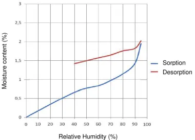
The reverse phenomenon, in other words, the water loss due to lower RH values, is called desorption.
Ideally, these values should match to adsorption values. However, the desorption is a slower process than
2. Heat Transfers and Hygrothermal Behaviour
11
Figure 2.4 - Hysteresis in mineral materials (adapted from Henriques, 2011)
As a function of relative humidity, the sorption isotherm allows the equilibrium of moister contents
with a hysteresis between humidification and dehumidification. Each material has his own S-curve which
characterizes it (Hens, 2012) (Figure 2.5).
Figure 2.5 - Sorption isotherm (Hens, 2012)
The mechanisms that bind water molecules depend on the value of relative humidity. For lower values
(less than 40%), the adsorption of water molecules at the pore walls occurs, whereas, for higher values,
capillary condensation on the water menisci formed by the adsorbed layers happens. The saturation zone is
achieved when the maximum hygroscopic moisture content at equilibrium is 98%.
Kelvin’s Law links the porous radius and the relative humidity value where saturation occurs (Henriques, 2011). For 20ºC the saturation graphic presented in Figure 2.6 shows that, the wider the pores,
the higher must be the relative humidity for capillary condensation.
M
ois
tu
re
c
on
te
nt
(
%
)
Relative Humidity (%)
12
Figure 2.6 - Saturation from Kelvin law at 20ºC (adapted from Henriques, 2011)
Water saturation ratio, designated by SR, is the actual volume of liquid water per unit of actual porous
volume and is represented in equation (10).
𝑆𝑅 = 𝑊𝐿∅. 𝜌𝜌𝑑 𝐿
(10)
In this equation 𝑊𝐿is the liquid mass of water content [kg/kg], 𝜌𝑑is the density of the dried earth
material [kg.m-3], ∅ is the porosity [-] and 𝜌
𝐿 is the liquid water density [kg.m-3].
The water content can be defined as the total mass of water, liquid plus vapour phase.
2.2.3. Moisture Transport
Moisture transport inside the porosity of a material is the result of different phenomena that lead to the
movement of the contained water in both liquid and vapour phases.
The passage of dry air increases the drying potential of an assembly and discharges water vapour before
it may condense. On the other hand, it may increase heat loss and heat gain substantially if placed close to
insulation.
As said before, water vapour and liquid water can be found in the porous network of a hygroscopic
material. Depending on the different phase the water is found, the transport will be different and follows a
different equation.
The first phenomena of heat flux described above - conduction - corresponds to one mass transfer:
diffusion. The water vapour diffusion process is a response to a gas concentration gradient where a natural
redistribution of that concentration will occur until equilibrium is reached (Henriques, 2011).
Fick’s Law is represented in the equation (11) and describes the water vapour diffusion.
𝐽 = −𝛿𝑎∇𝑝𝑣 (11)
In this equation J is the diffusion flux (in mol.m-2.s-1) and 𝛿
𝑎 is the permeability of the air into water
vapour (kg/m.s.Pa) that depends on the water vapour diffusion, the ideal gas constant and the absolute T.
Rad
iu
s
(m
2. Heat Transfers and Hygrothermal Behaviour
13
The ∇𝑝𝑣 is the gradient of the pressure. Fick’s Law was given in another form by Soudani (2016), presented
in the equation (12), which was used in Comsol Multiphysics simulation.
𝐽 = 𝑀𝑅𝑇 𝐷𝐻20 𝑒𝑣. ∇𝑝𝑣 (12)
In another way, Fick’s Law may also be written using the𝑀𝐻20 which is the molar mass of the water
molecules [g/mol], R is the ideal gas constant and is equal to 8,314 J/(K.mol), T is the absolute temperature
[K], 𝐷𝑒𝑣 is the effective diffusion coefficient [m2/s] and ∇𝑝
𝑣 is the gradient of water vapour partial pressure
[Pa].
Based on the equation of mass conservation of water vapour, equation (13) was obtained by Soudani
et al. (2016). The vapour mass conservation is equal to the transport of the vapour – explained before as the Fick’s Law - plus the phase change (capillary condensation and adsorption) within the material.
𝜕𝑚𝑣
𝜕𝑡 = ∇ ( 𝑀𝐻20
𝑅𝑇 𝐷𝑒𝑣. ∇𝑝𝑣) + 𝑚̇→𝑣 (13)
On the other hand, to study the liquid water transport there is the Darcy’s Law presented in equation
(14).
𝜙𝐿𝑉𝐿= −𝑘. 𝑘𝑟 𝐿
𝜂𝐿 ∇𝑝𝐿
(14)
In this equation 𝜙𝐿= 𝑆𝑟𝜙 [-] is the porosity filled by the liquid phase, k [m2] is the intrinsic permeability
of the porous medium, 𝑘𝑟𝐿 [-] is the relative liquid permeability, 𝜂𝐿 [Pa.s-1] is the dynamic viscosity of water,
equals to 10-3.
If the relative velocity of the liquid in the pores follows Darcy’s Law, neglecting the term of gravity,
the conservation of the liquid water mass can be deduced (Soudani, 2016) and it is presented in equation
(15).
𝜕𝑚𝐿
𝜕𝑡 = 𝜌𝐿. ∇ ( 𝑘. 𝑘𝑟𝐿
𝜂𝐿 ∇𝑝𝐿) − 𝑚̇→𝑣 (15)
2.3.
Thermal Behaviour of Building Materials
2.3.1. Thermal Transmittance
The thermal resistance is a performance indicator of the insulation of a certain wall. The behaviour
depends on the thermal conductivity, 𝜆 [(W/(m.ºC)] and the thickness, e [m], of the material. The thermal
resistance [(m².ºC)/W], also known as 𝑅𝑣𝑎𝑙𝑢𝑒 is given by equation (16).
14
The 𝑅𝑣𝑎𝑙𝑢𝑒is a measure of how well an insulation material will resist to the flow of heat or cold. With
higher values of thermal resistance, the insulation effectiveness is greater.
There is another indicator well-known as thermal transmittance, 𝑈𝑣𝑎𝑙𝑢𝑒 [W/m2.ºC] that is presented in
equation (17).
𝑈𝑣𝑎𝑙𝑢𝑒=𝑅 1
𝑣𝑎𝑙𝑢𝑒+ 𝑅𝑠𝑖+ 𝑅𝑠𝑒 (17)
For a horizontal heat flux, such as the case of a wall, the external and internal superficial thermal
resistances used was the European norms, from ITE50 (Santos and Matias, 2006). The internal thermal
resistance, 𝑅𝑠𝑖, is 0.13 (m².ºC)/W and for external thermal resistance, 𝑅𝑠𝑒, the value is 0.04 (m².ºC)/W.
The lower the 𝑈𝑣𝑎𝑙𝑢𝑒, the better will be the performance of the wall.
2.3.2. Thermal Inertia
Thermal inertia is the ability that prevents the flux from immediately passing through the wall. Instead,
the wall will be warmed up gradually and the accumulated heat will be stored inside the wall and released
gradually hours after. Stored heat inside a wall depends on many factors such as time, density, specific heat,
volume of the wall and finally, thermal conductivity. The delaying of the T transmission is called time lag.
It also depends on how fast the heat is absorbed and dispersed.
In conditions that the T in one side (for example, external temperature, 𝑇𝑒) is lower than on the other
side (internal temperature, 𝑇𝑖), the heat flux (q) can be calculated by equation (18). In the case the 𝑇𝑒 and 𝑇𝑖
have the same value, the flux that crosses the wall will be null.
𝑞 = 𝑈𝑣𝑎𝑙𝑢𝑒(𝑇𝑒− 𝑇𝑖) (18)
When a disturbance happens in a system, the thermal mass has a tendency to bring the material to a
new equilibrium T. The time lag represents how long it will take to reach this new equilibrium. The higher
the thermal mass is, the greater is the time lag.
A material that induces high time lags and low decrement factors provides almost constant inside
temperatures which results in a good comfort level. This was underlined by (Sun et al., 2013)
The decrement factor (DF) is defined in equation (19)
𝐷𝐹 = 𝑇𝑖𝑚𝑎𝑥− 𝑇𝑖𝑚𝑖𝑛 𝑇𝑒𝑚𝑎𝑥− 𝑇𝑒𝑚𝑖𝑛
(19)
In this equation, 𝑇𝑖𝑚𝑎𝑥, 𝑇𝑖𝑚𝑖𝑛,𝑇𝑒𝑚𝑎𝑥and 𝑇𝑒𝑚𝑖𝑛represent the maximum and minimum temperatures of
the interior and exterior surfaces, respectively.
The time lag (TL) is defined in equation (20)
𝑇𝐿 = 𝑡𝑇𝑖𝑚𝑎𝑥− 𝑡
2. Heat Transfers and Hygrothermal Behaviour
15
In this equation, 𝑡𝑇𝑖𝑚𝑎𝑥 and 𝑡𝑇𝑒𝑚𝑎𝑥 represents the time when the interior and exterior surface temperatures
are on their maximum. Analogously, it can also be calculated for the minimum peak.
2.3.3. Diffusivity and Effusivity
Diffusivity and effusivity are parameters used to quantify thermal mass of a construction material.
They enable the measurement of heat exchanges for different materials.
The thermal diffusivity, D [m2/s], expressed in equation (21), is the ability of the material to transfer
T variations. It shows how fast heat is spread inside a material. Thermal diffusivity is directly proportional
to the heat transfer rate, thus, heat transfer is inversely proportional to the heat capacity. Low values of
diffusivity will be able to buffer T variations.
In equation (21), 𝜆 is the thermal conductivity of the layer between the sensor and the surface
[W/(m.K)], 𝜌 is the dry density [kg/m3] and 𝐶
𝑝 is the heat capacity at constant pressure [J/(kg.K)]. The
lower the diffusivity is, the higher are the buffering effects of the material.
On the other hand, thermal effusivity, E [J/(kg.m2.s1/2)] is a measure of the ability of the material to
exchange energy with its surroundings and it is defined with the same variables that were used in diffusivity.
It is presented in equation (22).
𝐸 = √𝜆𝜌𝐶𝑝 (22)
The higher the effusivity is, the more quickly the material absorbs heat without T rise at its surface
which means that the wall is not going to store heat efficiently.
Recent studies evidence that earth materials, whether are dry or wet, seem to have a good compromise
between a low diffusivity and a high effusivity, which means that the outside temperature variations will be
lowered by the material. However, it is not capable of storing heat (Soudani et al., 2017).
2.4.
Hygrothermal Behaviour
Walls are exposed to thermal and hygric gradients. External walls surfaces interact with external
environment through the exchange of heat (convection and radiation), moisture (wind driven rain and
vapour diffusion) and finally, liquid water (sorption, desorption and capillarity). They also interact with the
indoor environment through the exchange of heat and water, both in liquid and vapour phases (Figure 2.7).
Since the experimental work that will be presented in this dissertation is performed inside a laboratory,
the variables related to solar radiation, wind driven rain and capillarity are not considered. The heat transfer
will be further discussed through T.
𝐷 = 𝜌𝐶𝜆
16
Interior T and RH can be significantly influenced by the interactions previously described (Janssen &
Roels, 2009). The transport and storage of heat and water inside the wall depends on construction materials
properties.
Rammed earth has a great thermal mass since it can absorb, store and release substantial amounts of
heat, keeping stable interior air T. On the other hand, it has a high hygric mass since it can absorb, store and
release significant amounts of water, keeping stable the RH on the interior (Allinson & Hall, 2010).
Nevertheless, the impact of evaporation and condensation is a non-negligible phenomenon on the
surfaces.
The use of surface film coefficients for heat transfer and thermal conductance does not reflect exactly
the reality. These coefficients are used to obtain simplified results in steady state, but then the moisture
buffering has no impact. The mass transfer causes energy displacement. This movement includes kinetic
energy and potential energy as a result of gravity, suction forces and pressure, which in turn induces heat
transfer (Fabbri, 2017). Each solid, liquid or gas at a certain T contains a quantity of heat per mass-unit,
given by equation (23).
In this equation, c is the specific heat [J/(kg⋅K)], T is temperature and 𝑡0 is the reference temperature.
The hygrothermal behaviour is the coupling between mass transfer (liquid and water vapour) and heat
transfer in the same porous material. It happens in a transient regime, where T and heat flux change with
time. The hygrothermal coupling is represented in Figure 2.7.
Figure 2.7 - Hygrothermal coupling (based on Soudani, 2016)
𝑄 = 𝑐 (𝑇 − 𝑇0) (23)
2. Heat Transfers and Hygrothermal Behaviour
17
The hygrothermal coupling is going to be measured experimentally, and more precisely the T progress
due to evaporation and condensation of the water vapour is measured during moisture ingress.
When energy is provided to a material, its T changes. However, during phase changes, the T of the
material stays constant. This happens because energy is required to change the phase of the material. Once
heat is added to a liquid, the molecules start to vibrate faster, and this allows the liquid to transform into
vapour.
The latent heat, L [J/kg] is obtained by the amount the heat energy, Q, per mass unit, m, required for
phase change to occur (equation (24)).
𝐿 = 𝑚𝑄 (24)
Rammed earth seems to be able to store latent heat because of liquid to vapour phase changes occurring
within the pores.This provides the high thermal mass of the material to avoid elevated temperatures in
summer and low temperatures in winter (Soudani, 2016).
The hygrothermal behaviour of rammed earth wall has been studied in situ by several researchers
(Soudani, 2016), (Taylor & Luther, 2004), (Taylor et al., 2008) and in laboratory by Chabriac et al. (2014,
2016). Most of them also made the laboratory characterization of the material. The hygrothermal properties
were also studied in laboratory by McGregor et al. (2016) providing the moisture buffering performance of
rammed earth and in comparison with compressed earth block and earth plaster samples. Penetration depth
below 2 cm were obtained for calcareous-clay materials formulations (McGregor et al., 2017).
The calibration procedure to monitor the hygrothermal behaviour of a rammed earth wall was defined
by Chabriac et al. (2014).
Allinson & Hall, (2010) created a model to study the hygrothermal behaviour of a cement stabilised
rammed earth building with vapour resistance renders and then validated the model with in situ
measurements.
Several research studies have been conducted to study other characteristics of rammed earth, such as:
impact of moisture in mechanical behaviour (Champiré et al., 2016); mechanical characteristics in
compression (Miccoli et al., 2014); thermal comfort and energy reduction (Taylor & Luther, 2004), (Taylor
et al., 2008); and finally, durability to external conditions (Bui et al., 2009).
The hygrothermal behaviour between other bio-based materials and the environment has been studied
by many authors for straw concrete walls (Rahim et al., 2017), wooden insulation panels (Serrano et al.
2016) and for hemp-lime (Holcroft & Shea, 2013), (Collet et al., 2013). The latter was also tested with
different coatings applied on the surface (Tran Le et al., 2016). These researchers measured the effect of
latent heat during moisture buffering tests where cycles of sorption/desorption with different ranges of RH
and different hour periods were simulated. The results underline that hemp fibre did influence the moisture
3. Methods and Materials
19
3.
Materials and Methods
3.1.
General Remarks
A rammed earth wall is monitored without and with two different types of thermal insulation applied
on its internal surface. This chapter describes the tested materials and the experimental tests performed.
This study was made using specific equipment such as heat flow meters, hygrometers and
thermometers. After an exhaustive set up and calibration of all sensors, the wall was submitted to several
tests where T and RH were the variables.
Throughout the tests, insulation improvements were made firstly in the chamber and then in the
rammed earth wall. The wall was insulated with a synthetic and waterproof insulation and compared to an
earth based insulation. The chamber improvements were verified by infrared thermography.
3.2.
Materials
A rammed earth wall was placed into a climatic chamber made with waterproofed cork with 10 cm
thickness. The rammed earth wall has 1.00 m in width, 1.50 m in height and 0.30 m in depth, as presented
in Figure 3.1 (a) below. The dimensions of the chamber are 1.20 m in width, 1.70 m in height and 1.90m
depth. The access to the interior of the chamber is made by two entrance doors, which allow both sides of
the rammed earth wall to be seen. The real chamber is presented in Figure 3.1 (b). A heater and a humidifier
are placed inside the chamber. On the other hand, outside the chamber is visible in Figure 3.1 (b) the wiring
which connects the devices and sensors to the computer that collects the data.
Figure 3.1 - Design of the climatic chamber (a) and the real climatic chamber (b)
The climatic chamber is situated inside a laboratory made of metallic walls, and between two similar
chambers. One of the entrance doors are side turned to the edge of the laboratory, and the other entrance,
on the opposite side, turned to the centre of the laboratory. Parallel to both entrance doors, the rammed earth
wall is inserted in the middle of the chamber. Near to the chamber there are two big garage doors, frequently
20
opened in Summer time. Above the garage doors are windows and early in the morning, the sun irradiates
in the direction of the chamber. For a better understanding, see Figure 3.2.
Figure 3.2– Chamber location in the laboratory
The rammed earth wall was already manufactured by Nicolas Meunier Company, specialist in rammed
earth. The earth used for the construction of the wall was taken from St. Antoin l'Abbaye region, in
Rhône-Alpes, France.
The earth composition is silt, sand and gravel which contains nearly 10% mass of aggregates with the
diameter greater than 40 mm. Moreover, the earth always contains clay that acts as binder between the
grains, in this case with approximately 16% mass. The grading curve of this earth may be found in Chabriac
(2014). The soil was stabilized with 2.5% mass of natural hydraulic lime NHL5 with the purpose of
increasing the durability and mechanical performance of the wall.
The rammed earth wall has been pre-fabricated, composed by several layers of earth with 10-15 cm
thick placed inside a removable metallic formwork. Each layer has been compacted with a pneumatic
rammer obtaining a final layer with 6-10 cm. The procedure was repeated until the experimental wall was
accomplished.
The mechanical properties of rammed earth walls depend on a few factors: granulometry of the earth,
moisture contents, compaction type and power, and finally, type and content of additions. These previous
factors define the rammed earth apparent density and porosity (Miccoli et al., 2014).
Some properties of this rammed earth wall were already studied elsewhere (Chabriac, 2014): heat
capacity 𝐶𝑝= 647 J/(kg.K), thermal conductivity 𝜆 = 0.64 W/(m. °K), porosity ∅ = 0.345, water vapour
diffusion coefficient 𝜇 = 9 and, at last, water absorption coefficient A= 0.37 kg/(m2.s1/2).
Considering that some properties of the rammed earth wall has already been studied by Chabriac
(2014), the aim is to continue his work, going further and applying two different insulations on the rammed
3. Methods and Materials
21
An expanded polystyrene board (EPS), a common synthetic insulation used nowadays, was applied.
This material is one of the most versatile insulations available: it has a low thermal conductivity λ=0.04
W/(m.°K), a light weight, it is easily shaped, as well as it is cheap. Nevertheless, its permeability to water
vapour is low. The aim was to see the hygrothermal behaviour of rammed earth when in contact with a
synthetic and waterproof barrier.
On the other hand, a hemp-lime plaster was applied to the same rammed earth wall. Besides being a
recyclable resource, the characteristics of this insulation is consistent with the behaviour of the rammed
earth wall since it allows the moisture to be released, avoiding condensation issues. The pore structure of
hemp-lime allows it to dampen variations in environmental heat and humidity (Shea et al., 2012), as well
as rammed earth. It also has a good thermal performance with a relatively low thermal conductivity λ=0.304
W/(m.°K) obtained from one tested sample. Other fibres have been studied and it was concluded that hemp
fibres are more resistant to biological decay when compared to other bio-based building materials, such as
straw (Shea et al., 2012). Due to their low mechanical resistance (Arnaud & Gourlay, 2012), hemp-lime is
mainly applied as wall insulation or even as roof and floor insulation.
Table 3.1– Materials properties
Material Thermal Conductivity (𝜆)
[W/(m. K)]
Dry density () [kg/m3]
Heat Capacity (𝐶𝑝) [J/(kg.K)]
Rammed Earth (RE) 0.640 (1) 1800 (5) 647 (1)
Polystyrene (EPS) 0.037 (2) 20 (6) 1500 (6)
Hemp-Lime (HL) 0.304 (3) 478 (4) 1100 (4)
Reference sources:(1) Chabriac, 2014; (2) Santos and Matias, 2006; (3) Sample tested by the author; (4) Rahim et al., 2017; (5) Hall & Djerbib, 2004; (6) Technical report GmbH.
With the lower density of the three materials, polystyrene requires more energy to raise the T 1ºC,
based on Table 3.1. In addition, it has the lower thermal conductivity which makes it the best insulation for
the rammed earth wall in terms of thermal performance.
Thermal resistance (R-value) for rammed earth wall is 0.47 (m2.ºC)/W according to its thickness (30
cm) divided by its thermal conductivity, presented in Table 3.1. Therefore, using Rsi and Rse provided by
Santos and Matias (2006), a U-value of 2.1 W/(m2.ºC) is achieved. When combined with 10 cm of EPS,
rammed earth reaches an R-value of 3.17 (m2.ºC)/W and a U-value of 0.3 W/(m2.ºC). Finally, for rammed
earth wall combined with 8 cm of hemp-lime plaster, it reaches R-values of 0.73(m2.ºC)/W and a U-value
of 1.1 W/(m2.ºC). In terms of thermal resistance, the best solution is the one with lower U-value, therefore
the rammed earth combined with EPS.
3.3.
Tests Procedure
To study the behaviour of the rammed earth wall, four constructive solutions were conducted. Firstly,
22
combination corresponds to constructive solution 1; the chamber is presented in Figure 3.3 (a) and the
rammed earth wall placed inside the chamber is presented in Figure 3.4 (a), both without any insulation.
Every test counts with the installation of three fans inside the chamber and the reason is explained below,
in chapter 3.5.
It was realized that the cork was not a proper insulation, because the outside conditions variation was
influencing the chamber variation. For this reason, polystyrene boards were added outside the chamber with
4 cm on the lateral sides of the chamber and with 10 cm on the top side of the chamber (where heat losses
were bigger as will be seen further on in chapter 4.2.2). In addition, in the interior side of the cork chamber,
was added a thermal insulation coating made by Granomural®. This thin insulation (3 mm) is an ecologic
solution based on wood fibre and cellulose, used both for thermal and acoustic insulation.
The improvements made outside the chamber are shown in Figure 3.3 (b) and inside the chamber in
Figure 3.4 (b), corresponding to constructive solution 2. As it can be noticed, one side of the chamber was
not insulated because it worked as the external side and, for this reason, it was determined that it would stay
always open to the outside environment. The described chamber insulation remained until the end of the
experiments.
Figure 3.3 - Improvements in chamber: constructive solution 1 (a) and constructive solution 2, 3 and 4 (b)
Afterwards, corresponding to constructive solution 3, the behaviour of rammed earth was combined
with 10 cm expanded polystyrene board (EPS) with a thermal conductivity λ=0,055 W/(m.°C). As said
before, the aim was to see the behaviour of rammed earth with a synthetic and waterproof insulation. The
board was placed on the interior side and was 2 cm distant from the wall, assured with spacers. This gap is
3. Methods and Materials
23
between the wall and the waterproof insulation were added, further explained in the next section. The
improvements on the rammed earth wall are shown in Figure 3.4 (c).
The purpose of the 4th and last constructive solution was to study the behaviour of the rammed earth
when combined with a hemp-lime insulating plaster, presented in Figure 3.4 (d).
Figure 3.4 - Improvements in rammed earth wall: constructive solution 1 (a), constructive solution 2 (b), constructive solution 3 (c) and constructive solution 4 (d)
The hemp-lime mortar is a bio-composite material which consists in a mixture of hemp shives, natural
hydraulic lime NHL 3.5 and water. This mortar was prepared inside a concrete mixer (see Figure 3.5 (a))
with a ratio of 10% mass of hemp, 46% of binder and 44% of water for the first layer and a ratio of 9%
mass of hemp, 40% of binder 51% of water for the second and third layers. The layers were applied with
an interval of 7 days, in order to allow the first layer to dry and gain resistance before the application of the
second. Before the application of the mortar layers, the surface was moistened with a sponge to improve
the adhesion. The hemp-lime mortar was applied by manual projection technique, visible in Figure 3.5 (b).
Besides, to obtain the real thermal conductivity value of the insulation, a small sample was gathered in
one mould with 12 cm of diameter and 8 cm of thickness (see Figure 3.6 (a)). The size of the sample is
representative of the insulation thickness. The thermal conductivity was tested in laboratory conditions at
24 ºC and 65% RH, in Faculdade de Ciências e Tecnologia da Universidade Nova de Lisboa, with a
ISOMET Heat Transfer 2104 equipment, with a 6 cm diameter contact probe API 210412, one month after
the preparation, when sample was already dried (see Figure 3.6 (b)).
(c) (d)