Clay Minerals (1993) 28, 509-530
P A R T I C L E S I Z E A N D S H A P E E F F E C T S IN
M A T E R I A L S S C I E N C E : E X A M P L E S F R O M P O L Y M E R
A N D P A P E R S Y S T E M S
J. M . A D A M S
ECC International, John Keay House, St Austell, Cornwall PL25 4D J, UK
(Received 6 January 1993; revised 23 April 1993)
ABSTRACT: Large quantities of clay minerals (and other micron-sized mineral powders) are used widely in materials science. Mineral fillers are major components, for example, of paints, rubber, plastics and paper and board. While the original object of such incorporation was to reduce costs, performance is now being "engineered" by design or choice of the relevant mineral particles. This paper concentrates on the use of mineral powders in polymer and paper science. In both application areas, the size and shape of the mineral particles can affect mechanical properties such as stiffness and tensile and impact strength. However, other characteristics are also modified. For example, the drainage rate in paper formation and the rheology of a polymer melt, properties which are critically important to the rate of processing of the relevant materials, can be greatly affected. Finally, the size and shape of the mineral particles also affect appearance, i.e. the smoothness, uniformity, optical properties etc. Mechanical and rheological data are presented for mineral-filled polypropylene, as are mechanical and optical data for filled and coated paper.
T h e r e has b e e n much interest in recent times in measuring the size and shape of small, micron o r sub-micron, particles. T h e priority assigned to the topic results from the fact that the subject is of m o r e than a c a d e m i c i m p o r t a n c e . M a n y of the most technologically i m p o r t a n t fluids are colloidal in nature; their b e h a v i o u r d e p e n d s on interactions b e t w e e n sub-micron particles and their surrounding fluids; interactions which d e p e n d on surface charge and chemistry, but also very critically on the size and shape of the particles themselves. T h e rheological b e h a v i o u r of t o o t h p a s t e s , paints and lubricating oils, for e x a m p l e , are all " e n g i n e e r e d " by suitable design o r choice of the r e l e v a n t colloidal particles.
P o w d e r e d materials of micron size are used widely in materials science. M i n e r a l fillers are m a j o r c o m p o n e n t s , for e x a m p l e , of paints, r u b b e r s , plastics of various kinds ( b o t h thermoplastics and t h e r m o s e t s ) and p a p e r and b o a r d . T h e original driving force for i n c o r p o r a t i o n of fillers was to reduce overall costs. H o w e v e r , in e v e r y case, a d d i t i o n of the filler modifies the p r o p e r t i e s of the material. I n d e e d , c o n s i d e r a t i o n of c o m m e r c i a l practice in the m a n u f a c t u r e of each of the m a t e r i a l s m e n t i o n e d a b o v e m a k e s it obvious that p o w d e r e d fillers are now selected carefully to e n h a n c e p e r f o r m a n c e in some way, w h e t h e r it be in terms of mechanical p r o p e r t i e s , surface smoothness or optical p r o p e r t i e s such as brightness o r opacity.
In this p a p e r , emphasis has b e e n p l a c e d on p o l y m e r s and papers. In each case, an a t t e m p t has been m a d e to show how the size and shape of the mineral particles d e t e r m i n e s p r o p e r t i e s of technical and c o m m e r c i a l i m p o r t a n c e .
E X P E R I M E N T A L
On occasion in this article, use is made of previously published data. However, whenever unattributed data are presented below, experimental procedures were generally as given in
Riley et al. (1990), McGenity et al. (1992b) and Adams & Walters (1993) (polymers) and
McGenity et al. (1992a) (paper).
The mineral pigments used were either calcium carbonates, talcs or kaolins. Where particle size data are quoted, they were obtained using a Micrometics Sedigraph. Aspect ratios fall generally in the order: calcium carbonate, kaolin, talc, mica. They were measured from shadowed electron micrographs. The polypropylene homopolymer employed throughout was ICI GW522.
P O L Y M E R S
Introduction
The original driving forces for the addition of mineral fillers to polymers was certainly economic. Typically, common (high volume) polymers cost around ten times the price of mineral fillers. However, in most, if not all, cases, the cost argument cannot be sustained. For examples, the incorporation of fillers into thermoplastics (compounding) is a costly process, sometimes totally cancelling out the advantage of introducing the filler. Why, then, are polymers filled? The answer is that fillers can give property improvements of various sorts; mechanical and rheological properties can be modified, as can electrical resistivity, the absorption of UV and IR radiation, optical clarity etc. The fillers serve a functional purpose.
Two topics of importance are considered: firstly mechanical properties--for these determine the end use to which the material can be put--and, secondly, rheological properties--for these determine the rate at which articles can be formed in moulding, and also the surface finish of the product. The main focus is on polypropylene (PP) as host polymer since it is very widely used in filled form. It is noted that, commercially in Europe, talc and calcium carbonate are the fillers normally employed, though small amounts of mica and wollastonite are also used.
Mechanical properties
The tensile, flexural and impact (Fig. 1) performance of a polymer are all affected by inclusion of filler.
Composite stiffness. The flexural modulus (stiffness) depends on the filler loading, but also on the filler type (Fig. 2), with the modulus increasing as the filler aspect ratio (AR) increases. The attention which has been given to the calculation of the moduli of heterogeneous systems has resulted in a reasonable understanding of the topic. Moduli can now be predicted fairly well from a knowledge of the moduli of the filler and polymer, the loading level, the aspect ratio (AR) of the filler and the degree of alignment of non- spherical (AR >1) filler aprticles.
In 1970, Padawar & Beecher considered the case of filling the polymer matrix with planar materials. Their theory allowed for the effect of particle edge-edge interactions, but not for flake misalignment. They obtained:
Particle size and shape 511
MECHANICAL PROPERTIES
9
Tensile
i
_9 Flexural
9 Impact
/ t / ; /
71 i
q~c(
F1G. 1. Schematic representation of different modes of deformation.
where Ecomp, Epol and Efil are the moduli of the composite, polymer and filler, respectively, and q~ is the filler volume fraction. The modulus reduction factor (MRF) is a fraction (-<1) which approaches unity with increasing flake A R and loading. The theory is successful in predicting qualitative trends.
More recently, Farber & Farris (1987) used analogies with the calculation of the viscosities of suspensions to develop a model to predict the elastic modulus of composites filled with spherical particles. Their model, which consists of coupled differential equations, can be solved numerically. In Fig. 3, it can be seen that there is a reasonable agreement with experimental data.
J. M. Adams
!:!
~
o,T
i i ~ i i i
0 10 20 30 40 50
Filler Loading / wt%
Fz6.2. Effect of filler loading on the flexural modulus of mineral-filled polypropylene: marble ([~), kaolin (B), talc (O) and mica (O) fillers.
w m
" u 0
(g
o
U.
o
Q
3
o . o 0 ~ . - . ~ 1 7 6 " " ~
~ 1 7 6
0 -"
10 20 30 40 50
Filler Loading / wt%
Fx6. 3. Comparison of experimental (O; Radosta, 1976) and calculated (Farber & Farris, 1987) flexural moduli for carbonate-filled PP.
aligned parallel to each other. This is achieved by choice of filler, and by careful design of moulding procedures.
Tensile properties. Our understanding of tensile strength (TS) is less advanced than that of stiffness. To obtain an estimate of TS, we can set upper and lower limits. These correspond to the case where (a) the filler is well bonded to the polymer and carries its share of the load, and (b) the filler is not bonded to the polymer at all and carries no load. In the first case, the TS is effectively unchanged with filler loading, while in the second, the TS decreases linearly with loading. The difference between these two models is too great for these considerations to be of predictive utility: experimental data are required.
Particle size and shape 513
~. 30'
2 4
_o 18-
! r i !
0 10 20 30
Filler Loading / vol%
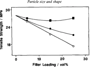
FIG. 4. Tensile strength of chalk-filled polypropylene as a function of the particle size of the filler. (2) 130 #In; 9 30/~m; 9 3.5 gm (Vollenberg, 1987).
size of the chalk particles. H e demonstrated (Fig. 4) that the TS remained high, even at 25 vol% loading, provided that the particles were small (few /,m). With larger filler particles, TS decreased with loading. His explanation for this p h e n o m e n o n made use of the concept of "blocking area". W h e n PP deforms, there is an elastic response, but localized and diffuse inelastic processes also occur (see e.g. Kinloch et al. (1985)). We have the total strain, e:
e = eel + elo c + edi ff
where eel, eloc, ediff are the elastic, localized and diffuse strains.
Since eloc is small, then:
e = eel + ediff,
i.e. a
e = ~ + edi ff
where E is the tensile modulus and a is the tensile stress.
So: a = E(e - ediff ).
For a to be maximized, ediff must be minimized, i.e. tensile strength is maximized if diffuse deformations can be blocked.
The blocking area (BA) depends on the n u m b e r and size of the filler particles: B A = C1 nr 2
where r is the particle radius and n is the n u m b e r of particles per unit volume.
Since n = C 2 . d p l r 3
where ~p is the volume fraction filled,
tensile strength is not the only important factor when a polymer composite is stretched. The mode of failure is important. With small filler particles, the strain at which breaking occurs is low and the fracture itself is sudden (brittle failure). With larger filler particles, the tensile strength is lower, but fracture is preceded by large strain deformation and necking (tough failure).
Impact strength. If impact strength is considered, there is an even lower level of predictive ability, even though the relevance of Griffith's (1920) flaw theory to filled polymers has been fully confirmed,
i.e. 2E.~,f
O - ~ . C
where crf is the fracture stress, E is Young's modulus, C is 89 length crack and ]/f is the energy
required to form a unit area of fracture surface.
Svehova & Poloucek (1987), for example, showed that the impact strength of a filled PP depended on the number of particles (or aggregates arising from poor dispersion during processing) which were >10/~m. The importance of the qualification in the last sentence is emphasized in Fig. 5. Depending upon the intensity of mixing, the same filler can be dispersed as individual (sub-micron) particles, or can exist in the composite in the form of aggregates. The effect on impact strength is dramatic: that containing the poorly-dispersed filler had an impact strength <25% of that containing the well-dispersed filler.
On occasion (see e.g. Stanford & Bentley, 1989), impact strengths have been related by fracture mechanics studies to the fracture toughness of the composite, with high toughness being thought to be due to retardation of crack propagation by blocking (Cook & Gordon,
1964; Vollenberg, 1987) or pinning (Green et al., 1978a,b), though the mode of local plastic
deformations are also known to be important in these non-brittle systems (Kinloch et al.,
1985).
Flexural/impact balance. Of practical importance is the need for stiff composites which have high impact strength. This is, however, not usually achieved (Fig. 6). It is clear that a correlation exists between the two properties and, in general, one is enhanced at the expense of the other.
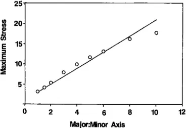
To investigate the effect of particle A R on impact strength, Riley et al. (1990) used finite
element methods to calculate the stresses in the region of an elliptical hole in an homogeneous polymer. The maximum stress was determined as a function of the major : minor axis ratio of the ellipse for a material subject to a uniform tensile stress. It was shown (Fig. 7) that high axial ratios were associated with high stresses at the (sharp) edges of the hole. Thus, high A R filler particles, which are needed to achieve the highest composite stiffnesses, inevitably cause high stresses in the polymer matrix near the particle edges; they facilitate failure under impact. This simple analysis may well explain why the stiffest composites are normally also the weakest under impact conditions.
Of great importance, however, is that incorporation of well-dispersed low AR particles can lead to enhancement of both stiffness and impact strength. The former is easily understood. The modulus of the filler is greater than that of the polymer: stiffness is enhanced, but not to the degree that would have occurred with a high AR filler.
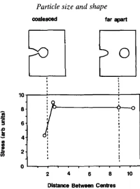
To understand the effect of low AR particles on impact strength, Riley et al. (1990) again
Particle size and shape 515
a
b
FIG. 5. Fracture surfaces of carbonate-filled polypropylene. In (a) the filler (86% <2 /~m) was dispersed using low shear intensity (Brabender plasticoater) while in (b) the same filler was dispersed
J. M. Adams
,
g.
r 5"
4.
..n
- t
0 3-
2-
v,
_o 1"
i l k
i w i
0 4 8 12 16 20
Charpy Impact Strength / kJ/m 2
FIG. 6. Plot of flexural modulus v s . impact strength for mineral-filled polypropylenes. The envelope
limits contain data collected for different filler levels (0-50 wt%) of calcium carbonate, kaolin, talc and mica. Of the specific data shown, (3 represents carbonate (86% <2 #m) filled polymer at 20, 30 and 40 wt% loading; 9 represents talc-filled (50% <2 #m) polymer at the same loading. * Indicates
the properties of the unfilled polymer.
25"
w 20-
r
2
_E 15"
"~ 10-
0 12
/oz
i w i i
2 4 6 8 10
Major:Minor Axis
FIG. 7. Maximum stress (arbitrary units) around an elliptical inclusion in a homogeneous polymer matrix.
coalescence. It is reasonable to assume that this reduction in stress would retard the propagation of the crack (Cook & Gordon, 1984). Thus it is inferred that the effect of the low A R particles is to block propagation of cracks and thereby to enhance the impact strength.
Particle size and shape
517coalesced far a p a r t
t 0
10
8 "
e.
= 6 '
,D
~ 4-
m
2 -
I
i I t t
I i I I i
2 4 6 8 1 0
Distance Between Centres
FIG. 8. Approach of a crack to a circular inclusion in an homogeneous polymer. The distance between centres is in terms of number of "particle radii".
with as few particles as possible > 10 #m. (iii) The stiffness of a polymer/mineral composite is enhanced by use of high loadings of high aspect ratio filler particles. (iv) High aspect ratio fillers lead to large stresses in the polymer near the filler edges. Therefore impact performance is poor. (v) Use of low aspect ratio fillers gives moderate improvement in stiffness, but can also lead to enhancement of impact strength.
Rheological properties
Background.
The rheology of a filled polymer determines the rate at which the material can be processed, and also the surface finish, since this is determined to a large extent by the setting of the flowing polymer against a mould. The following short discussion is restricted to consideration of steady shear flow and oscillatory shear flow.Consider a steady simple shear flow, with velocity components, in a suitable Cartesian reference frame, given by
v• = ~y, Vy = V z = 0 ( 1 )
where ~, is the (constant) shear rate. The corresponding stress distribution for a non- Newtonian liquid can be written in the form
O'xy = O ( ~ ) = ])1] ( ] / ) , O'xx - - Oyy = N1 (]?), (2)
oyy - Ozz = N2 (~), with all other values of Oik zero,
518 J. M. Adams
departure of 7 (~') from a constant value and non-zero values of Nx (~') are viewed as evidence of non-Newtonian behaviour.
The viscosity can be measured (at different shear rates) using capillary rheometers or conventional rotational instruments, while the first nor/mal stress difference is most easily obtained using the latter. Further information can, however, be obtained from gathering data under a small amplitude oscillatory shear flow. We have:
Vx = 0;09 y e i~ •y = v z = 0 , (3) where o~ is a small amplitude. The corresponding stress distribution can be written in the form
O'xy = 7 " 0 l to e i ~ , other Oik zero, (4)
where 7* is the so-called complex viscosity and is in general a function of the frequency o9. It is usual to write
iG'
7" = 7 ' - - - (5)
tO
where 7' is the "dynamic viscosity" and G ' the "dynamic rigidity". The departure of 7' from a constant value as tO increases and the appearance of non-zero and significant values of G' are both indicative of a viscoelastic response.
The modulus of the complex viscosity is given by
17"1 = 7') 2 + (6)
and according to the Cox-Merz rule (which is found to be reasonable for polymer systems but not for colloids (Al-Hadithi et al., 1992)), the 17"1 against tO curve should be similar to
the 7 against ~ curve.
Experimentally, it is important to make sure that the oscillation amplitude is small enough for non-linear effects to be ignored. This can easily be accommodated (in principle at least) by carrying out measurements at two values of ol and verifying that the 7' and G' values so determined are independent of strain amplitude.
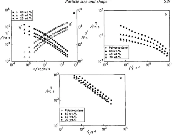
Rheological performance of filled PP. All data given below were gathered at 195~ around 30~ above the melting point of the host polymer (Adams & Walters, 1993).
Figure 9 shows very clearly that increasing the filler concentration increases both the viscosity and the elasticity. The effect of the 20 wt% loading is hardly noticeable, but by the time the loading has reached 60 wt% the effect is substantial. Interestingly, at the 60 wt% loading, it was found that the initial values of 7' and G' at any frequency were much higher than those taken after a period of oscillatory shear, indicating that relative particle arrangement (or particle orientation with anisotropic particles) must be a factor of relevance. The data presented are those taken after the samples had been "pre-sheared".
The effect of particle size is demonstrated in Fig. 10. There is little difference between the data for the two different size (carbonate) fillers until 60 wt% loading is reached. At this level, the consistency is higher for the finer filler.
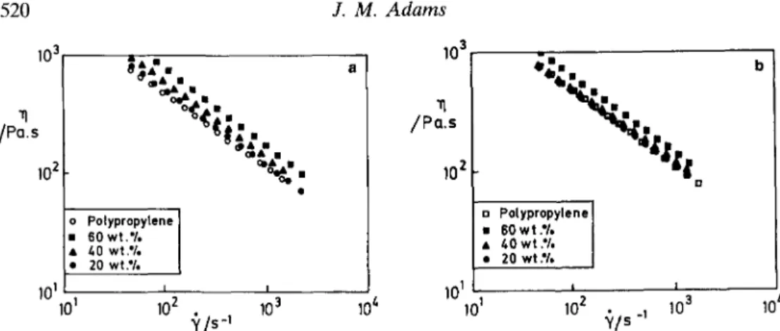
In Fig. 11, data are presented for the talc and carbonate, (i.e. high and low A R ) of similar particle size. It can be seen that both types of filler give rise to similar rheometrical behaviour, but that the viscosity/consistency is lower with the higher aspect ratio filler.
i0 ~ ~q'
~ / P Q . s
10 3
Particle size and shape
iO s
60 w t " / ' T
::~
~0wt ~/e. o 20 w t . % ]
9
a[3~ G'
"q' i
9 9"...
,~-,, B~_ ~ ~,."oOOo..aSg~,ll~ 9 3 o
[3 82 " 9
[3:, ,,, [ 3 . . : - , . . ,,, o o . . : . " . .
AO013 I:e& & I l l
[3 a IAA
~' 0
10 2
10 -~
i0 s
a
iO s G ~ /Po 10 & iO s i00 i0 ~ 102 i03
~ / r o d s / s
10 3 II
/PQ.s
102 I0~i01
I0 s
.q
//PQ. S I I I
I I I
lO~ i i I i i I i I I I
o PolypropyLene] 9 9 IDIO 9 9
9 6 0 w t . % /
&O w t .'/. / " % ~ 9
2o wt../, j 9
10 3 ~ J.
I0 "2 I0-I .~, / s -I I00
t~,"
9~o~o w. 9 9
ol& 9
z.d,
Polypropylene
60 w t . % &O w t . % 20 wt.%
I I
10 2 10 3
~ / s , i0 ~
519
101
FIG. 9. Rheological data for PP filled at different loadings (20, 40, 60 wt%) with a chalk filler having 6 wt% >10 #m; 49 wt% <2 #m. (a) Oscillation data, (b) data obtained by rotational rheometry,
(c) high shear rate data from a capillary rheometer.
10 s 106 10 s 106
a b
9 D
9 9 ..
10~ ~ @@66 " 10G. 104 ~' "..m.lm ,.,,..XXA~ G
r " ' G
/ P o . s "q / P a /Po.s [] A i&lll l
~a~ aa /iliL
na&'~ =Aime, b l i b Q A ~ m I
% 'L,L
A t~
10 2 I , i ]0 3 10 2 I I I 10 3
10 -t 10 o 10 ~ 102 103 10 -~ 10 o 10 ~ 10 2 103
t o / r a d s / s t o / m d s / s
FIG. 10. Rheological data illustrating particle size effects. Data presented for 60% <2 #m (E2,I) and 49 wt% <2/~m (A, 9 calcium carbonates. Oscillation data are shown for (a) 40 wt% and (b) 60 wt%
loadings.
distinguishable from those for the p o l y p r o p y l e n e h o m o p o l y m e r itself, even at higher loadings (e.g., Fig. 12).
O n e final i m p o r t a n t point can be d e r i v e d from investigating data from a wide range of shear rates. A n a t t e m p t has b e e n m a d e to bridge the d a t a sets o b t a i n e d at low shear rates (rotational instrument) and high shear rates (capillary) using the Cox Merz rule. T h e rule works very well for the h o m o p o l y m e r and at 20 wt% filler loadings but is c o m p l e t e l y
103
11 /Po.s
102
o
Polypropylene]
9 60 w t . ' / . I9 /00 wt.'/. I 9 20 wt.'/, j
I 0 1 1 ~ 0 4
X/s-'
10 5
-q /Po.s
i0 ~
103 . - - - . o H m
/ P a . s " ' "
lo 2
gJt I
t l
a Polypropylene] 9 60 w t .'I, [
9 40 wt.'/, I
9 20 w t ' / . j
101101 _L Z
10 2 ~/~ -' 10 3
10 3
10-2 10 ~
FIG. 11. Data for fillers of different shapes are presented at different loadings (a) calcium carbonate (AR -l-2) and (b) talc (AR ~50). Particle sizes are similar.
10 5 10 s 8
a /PO.s 9 a
= N1 10t' ~ . a N1
N I 9 a
a / P o 10 l' 9 9
11 9 9 103 9
i , 102 103 t i
10 -I I00 I0 ~ I0-2 i0-~ i0 o
~/s-1 ~/s -~
F16. 12. First normal stress differences are similar for (a) unfilled and (b) 60%-filled PP (chalk filler used; 49 wt% <2 ym).
10 ~ IO s 10 ~ N1 Pa 10 3 102
inadequate for the higher concentration levels (Fig. 13). This behaviour is probably not
unexpected in view of the detailed study of A1-Hadithi et al. (1992). Quite simply, the Cox
Merz rule is obeyed for materials that are basically polymeric but fails for materials that can be regarded as concentrated suspensions in a polymeric matrix; i.e. the failures of the rule at higher loadings is evidence in support of interparticle interactions (of unknown type) at higher filler levels.
Summary. (i) Incorporation of filler increases the viscosity, but the basic shear-thinning
behaviour of the host polymer is unaffected. (ii) Decreasing the filler size increases the viscosity. (iii) Increasing the aspect ratio of the filler (at approximately the same size) decreases the viscosity. (iv) At higher (filler) concentration levels, failure of the Cox Merz rule suggests interparticle interactions.
P A P E R
Introduction
Particle s&e and shape 521
Paper filling
In the basic paper-making process, a low consistency ( - 1 wt% solids) suspension containing wood fibres, mineral filler and various polymeric substances is deposited on a moving wire mesh. After dewatering, the paper consists of an overlapping and bonded fibre network (Fig. 14), within which is the trapped (and bonded) mineral filler particles. Typical loading levels vary in the range 0-30 wt% filler, depending upon a variety of factors. Addition of fillers normally improves the smoothness and opacity, of paper, and the brightness, provided that the filler is brighter than the pulp (which is usually the case). Printing performance is also enhanced: prints are more uniform with filled papers and the image is usually sharper. Moreover, the "strike through" of the ink is much reduced. These general considerations were covered by Beazley (1991). However, the detail of the effects
of variation in size and shape of the filler have been addressed by Beazley et al. (1979) and
by Bown (1985a,b). The data presented below are essentially drawn from that work. Page (1969) provided an empirical relation between tensile strength and various fibre properties:
1 B
- = A + - -
T b(RBA)
where T is the tensile strength of the paper, RBA is the relative bonded area between fibres in the sheet, b is the bond strength per unit area, and A and B are constants depending on fibre properties.
10 5 10 5
a
I P a . s
10 3
9 9 9 9
Cox-Merz Rule %
o 1 x 20mm Cop ary
I I I I I
10 0 . 10 2
W s -~
10 s 10 3
/ P o. s
it 9 9 9
/Pa.s
lO 3 ~ -
-, . O0 o
Steody Sheor (WR) ~ o
: Cox-Merz Rule 0Oo
o t x 2 0 m m Copi o.ry
101 , I i ~ i
10 -2 10 0 , 10 2 10 z'
• / s -~
F[6.13. For (a) unfilled or (b) 20% filled PP, the Cox-Merz rule is satisfactory; at 60%, however, (c) loading, the rule is disobeyed (chalk filler; 49 wt% <2/~m).
101 101 I I i I I
10 -2 10 t, 10 -2 10 0 . 10 2 10 z'
If the assumption is made that the bonded area is reduced in proportion to the surface area of the filler added, with the strong fibre-fibre bonds being replaced by weak filler/filler
bonds, it can be shown (Beazley et al., 1979) that:
TTo/(To - 7) should be linearly related to (1 - x)/xS
where x is the fraction of filler present, S the surface area of filler, T the tensile strength with x filler present, and To is the tensile strength of the unfilled paper.
Experimentally, Beazley et al. (1979) also showed that the burst factor B is strongly
related to the tensile strength. Hence BBo/(Bo - B) should be linearly related to (1 - x)/xS
and B and Bo are the burst factors and loadings of x and zero respectively.
The effects of particle size on properties of interest: drainage (which controls the speed at which the paper machine can be run), porosity (which influences printing) and light scattering (which determines properties such as brightness and opacity) have been summarized in Fig. 15. Essentially, as the filler is made finer, drainage time increases, a negative factor, but porosity is decreased (printing improves), and the light scattering increases (brightness and opacity improve). The effects are quite dramatic. The shape of the filler particles is also of importance. For example, in Fig. 16 the effect of changing from blocky to platey fillers can be seen. Platey fillers give papers with higher gloss and lower porosity (and hence better printing properties), both attractive features.
For papers which are not coated before use, such as the supercalendered grades used for magazines, filler loading and type are chosen to optimize gloss and print gloss. They are platey, but the fineness of the filler has to be balanced between the need for low porosity (printing performance) and drainage (production rate).
Summary. (i) Incorporation of a filler in the paper-making process decreases drainage
time (i.e. increases potential production rates), decreases strength, decreases porosity, and
Particle size and shape 523
13'
Q
E 8,
no filler
ller
i
20 40 60 80
32
_c
E
15 16
D .
wt% <2 )Jm
600"
580"
560.
m
i 540
~m 520
"I
g
i
20 40 60 80
wt% < 2 prn
20 40 60 80
wt% < 2 ,um
F16.15. Effect of variation in filler particle size on (a) drainage time, (b) porosity of the sheet and (c) light scattering coefficient. The filler used was a kaolin; 50 wt% <20/~m.
increases smoothness and gloss. (ii) The effects depend on particle size, with finer fillers slowing the rate of drainage, giving high strength reductions, but giving smoother and glossier sheets. (iii) Particle size is also important. Platey fillers again reduce porosity and increase smoothness and gloss (improved printing performance).
Paper coating
40-
38
. /
m ~ platey
(~ 32.
28,
0
24' blocky
5 10
36" p,
o
, . . . .
12
b
blocky
platey
15 20 25 30 5 10 15 20 25 30
wt% filler wt% filler
F[6.16. Effect of variation in the filler aspect ratio on (a) paper gloss and (b) porosity of the sheet. The blocky filler was chalk (AR ~1-2); the platey filler was kaolin (AR ~30~0).
~
backlng roll
blade ~
paper web
(a) LDTA: Roll Applicator
k•
backing roll
blade ~ x ~ . ~
/ paper web
,,
,o,:
(b) SDTA: Short DweU-tlme Applicator
Particle size a n d shape 525 applies a relatively thick layer of coating colour to the web as it passes between the roll and a larger backing roll. The positioning of the applicator as much as 1 m before the metering blade results in a significant 'dwell time' during which the wet colour sits on the base-sheet before it reaches the blade. This dwell time can vary from between one tenth of a second for a relatively slow machine running at 500 m/min to as little as a few hundredths of a second for machines running at 1200-1500 m/min. Even at the highest speeds, the dwell time of a roll applicator system is sufficiently long for the coating colour in immediate contact with the relatively absorbent fibre network of the base-paper to undergo significant dewatering and, hence, increase in content of solids which can, on occasion, give problems at the blade arising from the onset of dilatent rheological behaviour. The short dwell coater (Fig. 17b) was designed to reduce the dwell time of the fluid on the paper by applying the colour immediately prior to the blade using a recirculating system and thus overcoming the perceived disadvantage of dewatering before the blade. After coating, drying is accomplished using I R or thermal procedures.
In the coating process itself, and in subsequent printing, the size and shape of the pigment particles is of great importance. For example, the gloss of a coated sheet is dependent on the coverage of the fibres provided by the coating, especially on the tops of the fibres, and on the roughness of the coating (Gate & Leaity, 1991). The roughness on the surface of the coating has two principal components which combine to produce the surface topography which affect gloss. Firstly, the pigment particles themselves contribute to the small-scale microroughness by virtue of their size and shape, and the way in which they pack together on the paper surface. Secondly, the base-paper fibres lying underneath the coating influence the surface roughness (especially at low coatweights) because the small amount of coating does not totally match the size and shape of the fibres. During and after coating, the coating suspension dewaters into the base-paper, in addition to being dried by external means. Fibre coverage and roughness differ depending upon applicator type (dwell time),
low t o r t u o s i t y
I-"-I F-q F-I~F--I r--I U~ff-]
U ~ F-l U 2 ~ U ~
U D
F-I
E-If
i UZI FIll-71F-I U::]
z - d i r e c t i o n
h i g h t o r t u o s i t y
[
i f
i I ~ - - 1
C - - 1
U'----q f ~ . } 1
J
i
i f - - - ~ F - - - - q 1 S - - ]
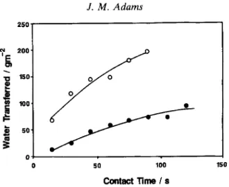
FIG. 18(a). Schematic representation of the packing of blocky and platey particles. The tortuosity is defined as the "path length" through the pore system divided by the total thickness of the layer. Tortuosity increases with particle AR and with decreasing particle size. The amount of fluid which can pass through such a pore system in unit time (dQ/dt) = :r pr4/8~IL, where P is the pressure applied
j
O
O 50 100 I50
Contact lime/s
FIG. 18(b). Dewatering data for slurries of kaolin ( 0 ) and calcium carbonate (O) of the same particle size (80% wt% <2/~m). The amount of water transferred through unit area of a millipore membrane
is quoted in each case.
250
200
"0 150
o
'~W 100
50"
Fluid -_..._.._
Capillary
. ~ ' ~ V i d e o Camera
V9
Moving Platform VDU
Basepaper
7 _=
E
_8
lU
Image 89 ~ ~
Analyser lime / min
I-1 \ []
0 <>~<>~O--O-BASE B
BASE
FIG. 19. (a) Schematic representation of the method used to generate data on base-paper sorbency. The tip of the capillary is brought into contact with the paper. The height of the fluid column is then followed with time. (b) Typical data for three commercial base-papers used for lightweight coating.
Particle size and shape 527 base-sheet absorbency and the dewatering rate of the coating colour, a property which depends on the presence (and type) of soluble polymeric additives, but also on the inherent dewatering properties of the pigment. The optimization of paper coating requires careful choice of the pigment and colour formulation to suit the base-paper characteristics and type of application.
If consideration is given initially to the pigment, it is obvious that the tortuosity of the pore system in a coating colour or in a coating depends strongly on the particle A R (Fig. 18). It is also clear that the amount of material which can travel through the pore system in unit time is related to the radius of the pores and also to the tortuosity. For typical pigments used in paper coating, simple dewatering tests demonstrate (Fig. 19) very different performance characteristics. Thus, if coating formulations based on these pigments are coated onto base- papers of different absorbency, possibly using different applicator systems, very different results might be obtained.
A study of the coatings produced using a high AR pigment shows (Fig. 20) that gloss is independent of the absorbency of the base-paper. On the other hand, pigments of lower AR give lower gloss, presumably a result of increased surface microroughness. However the gloss of the coating is very dependent on the degree of sorbency of the base. In addition there are also significant differences in gloss when different applicators are used (Fig. 21). Why is this?
Gloss is very dependent on coverage of the base-paper fibres. Not only does poor coverage reduce the overall gloss of the sheet; it also exaggerates problems of gloss and brightness/opacity variation (known as 'mottle'). Coverage is best assessed by examining cross sections of paper (prepared after embedding in resin) using optical or electron
microscopy (Bown et al., 1987; Fig. 22). By measuring the distance A and B from a
6 5
60
s5
8
m
r
5045
40
35
. f ' "
, , j ~
[] absorbe..
[ ] n o n - a b s o r b e n t
4 6 8 10 12 14
- 2
Coatw~ght / gm
Gloss
55 t
A ~
~
[] LDTA
/~ SDTA
so ~ A "~
40 / 1
[]
30
~ / ~ ~
~]-]~'~'~
non-absorbent
25
6 S 1'o 12 14 18
- 2
C o a t w e i g h t / g m
Fro. 21. Gloss data for calcium carbonate (blocky pigment) coatings on "sorbent" and "non-sorbent" bases. Application was made by both short dwell and roll applicator systems.
REFERENCE
STRIP
base/coating
I
coating sm'face profile
t
coating layer
interface profile ._J e
~
A
coating penetration
FIG. 22. Schematic cross-section of a coated paper (embedded in resin). The coating surface profile is obtained by stepwise measurement of A, while the base/coating interface profile can also be
Particle size and shape 529 reference line, the profiles of b o t h the t o p surface of the coating and the coating b l a d e interface can b e r e c o r d e d . The m o r e closely the c o a t e d surface follows that o f the base, the b e t t e r is the coverage o r c o n t o u r coating p r o p e r t y of the pigment.
Platey pigments retain w a t e r well in their t o r t u o u s p o r e systems. Coating p e r f o r m a n c e is, t h e r e f o r e , relatively unaffected by the type of base o n t o which it is c o a t e d . T h e coating colour covers the fibres well since t h e r e is little p e n e t r a t i o n of the base, a c o n s e q u e n c e o f the limited r o t a t i o n of the high A R plates of the p i g m e n t which is possible in the restricted space b e t w e e n the cellulose fibres o f the base, i.e. the p i g m e n t "bridges" b e t w e e n the fibres.
O n the o t h e r h a n d , the low A R pigments d e w a t e r very rapidly. P e r f o r m a n c e is very d e p e n d e n t on the base type and dwell time. O n a n o n - s o r b e n t base, the coating colour flows rapidly into the p o r e s of the b a s e - p a p e r , giving p o o r coverage while, on a s o r b e n t base, the colour loses w a t e r rapidly, giving g o o d coverage due to the i m m o b i l i z a t i o n of the pigment. T h e lower gloss seen when dwell losses are larger is a result of g r e a t e r swelling o f the b a s e - p a p e r .
T h e differences seen when different types of coating heads are used arise from the different timescales for which the coating colour is in contact with the base b e f o r e the excess is " d o c t o r e d " off at the b l a d e . It is found that even coating is achieved with short dwell coaters b y using p i g m e n t s of low d e w a t e r i n g rates. O n the o t h e r hand, for roll applicators, high p i g m e n t d e w a t e r i n g rates are a d v a n t a g e o u s .
Summary. T h e size and shape of the p i g m e n t particles used in p a p e r coating d e t e r m i n e s the p o t e n t i a l gloss o f the system. The factors of i m p o r t a n c e are: (i) c o v e r a g e - - o b t a i n e d t h r o u g h use o f p l a t e y pigments o r t h r o u g h r a p i d d e w a t e r i n g of b l o c k y pigments; (ii) the relationship b e t w e e n the w a t e r r e t e n t i o n of the coating colour and the w a t e r a b s o r p t i o n of the b a s e - p a p e r ; (iii) the type of coating h e a d used (which d e t e r m i n e s the length o f time the coating colour is in contact with the p a p e r and, hence, the d e g r e e of d e w a t e r i n g into the base).
ACKNOWLEDGMENTS
The information presented in this article has been produced by a large number of my colleagues in ECCI. I take this opportunity to thank all of those involved in Polymer and Paper Research: that the numbers involved are so large is my only excuse for thanking especially those who led the relevant Research Groups, i.e. Richard Bown, Pat Gane and Phil McGenity.
R E F E R E N C E S
ADAMS J.M. & WALI'ERS K.W. (1993) Effect of filler morphology and surface chemistry on the rheological properties of filled polypropylenes. Makromol. Chem. Macromol. Sym. 68, 227-244.
AL-HADITHI T.S.R., BARNES H.A. & WALTERS K. (1992) The relationship between the linear (oscillatory) and nonlinear (steady-state) flow properties of a series of polymer and colloidal systems. Colloid Polym. Sci. 270, 40-46.
BEAZLE'r K.M. (199t) Mineral fillers in paper. Part I. Basic physical and chemical properties; production technology. Paper Conservator 15, 17-27.
BEAZLEY K.M., DENNISON S.R. & TAYLOR J.H. (1979) The influence of mineral fillers on paper strength: its mechanism and practical means of modification. ESPRI European meeting, Brussels. Vol. 11, 217-238. BOWN R. (1985a) The use of filler in newsprint: a review of the technical aspects. PTS Paper Making Sym., Munich. BOWN R. (1985b) Fillers for uncoated groundwood papers. Proc. PPI Conference on Woodcontaining Papers, New
York.
Cook J. & GORDON J.E. (1984) A mechanism for the control of crack propagation in all-brittle systems. Proc. Roy. Soc. A282, 508-520.
FARBER J.N. & FARRIS R.J. (1987) Model for prediction of the elastic response of reinforced materials over wide ranges of concentration. J. Appl. Polym. Sci. 34, 2093-2104.
GATE L.G. & LEAITY K. (1991) New aspects on the gloss of coated paper. Proc. Tappi Coating Conference, Montreal, Publ. Tappi Press, Atlanta.
GREEN D.G., NICHOLSON P.S. & EMBURV J.D. (1979a) Fracture of a brittle particulate composite. Part 1. Experimental aspects. J. Mater. Sci. 14, 1413-1420.
GREEN D.G., NICHOLSON P.S. & EMBURY J.D. (1979b) Fracture of a brittle particulate composite. Part 2. Theoretical aspects. J. Mater. Sci. 14, 1657-1661.
GRIFFITH A.A. (1920) The phenomena of rupture and flow in solids. Phil. Trans. Roy. Soc. A221, 163-198. K1NLOCH A.J., MAXWELL D.L. & YOUNG R.J. (1985) The fracture of hybrid-particulate composites. J. Mater. Sci.
20, 4169--4184.
MCGENITY P.M., GANE P.A.C., HUSBAND J.C. & ENGLEY M.S. (1992a) Effect of interactions between coating colour components on rheology, water retention and runnability. Proc. Tappi Coating Conference, Orlando. Publ. Tappi Press, Atlanta.
MCGENITY P.M., HOOPER J.J., PAYNTER C.D., RILEY A.M., NUTBEEM C., EL~fON N.J. & ADAMS J.M. (1992b) Nucleation and crystallisation of polypropylene by mineral fillers: relationship to impact strength. Polymer 33, 5215-5224.
PADAWAR G.E. & BELCHER N. (1970) On the strength and stiffness of planar reinforced plastic resins. Polym. Eng. Sci. 10, 185-192.
PAGE D. (1969) A theory for the tensile strength of paper. Tappi J. 52, 674-681.
RADOSTA J.A. (1976) Impact and flexural modulus behaviour of calcium carbonate and talc filled polyolefins. SPE Technical Papers 22, 465-471.
RILEY A.M., PAYNTER C.D., MCGENITV P.M. & ADAMS J.M. (1990) Factors affecting the impact properties of mineral filled polypropylene. Plast. Rubber Proc. Applic. 14, 85-93.
STANFORD J.L. & BENTLEY S.R. (1989) The tensile and impact properties of polypropylene composites containing chalk (calcium carbonate) and wollastonite (calcium meta silicate) fillers. Filpas '89- The Fillers Conf. Publ. PRI, London, Paper 18.
SVEHOVA V. & POLOUCEK E. (1987) About the influence of filler particle size on toughness of filled polypropylene. Angew. Makromol. Chemie 153, 197-200.
VOLLENBERG P.H.T. (1987) The mechanical behaviour of particle filled thermoplastics. PhD thesis, Technische Univ. Eindhoven, Netherlands.