UNIVERSIDADE DE LISBOA
FACULDADE DE CIÊNCIAS
DEPARTAMENTO DE FÍSICA
Cholesteric liquid crystals confined
in toroidal droplets
Ana Regina Azevedo da Luz Fialho
Dissertação
Mestrado em Física
( Área de Especialização: Física da Matéria Condensada e
Nanomateriais )
Orientação: Professora Doutora Margarida Telo da Gama
e Doutor Nuno M. Silvestre
Acknowledgements
First of all, I would like to thank my thesis supervisors Margarida Telo da Gama and Nuno M. Silvestre, and the Principal Investigator of the project that led to the development of this thesis, Nelson R. Bernardino, for all the help and guidance they have given me during the development of this work. I am grate-ful for their patience and for all the discussions and insightgrate-ful comments. I also acknowledge the support from the Portuguese Foundation for Science and Technol-ogy (FCT) through grants PTDC/FIS/119162/2010, EXCL/FIS-NAN/0083/2012, SFRH/BPD/63183/2009(NRB), and SFRH/BPD/40327/2007(NMS), which have made this study possible.
I would also like to thank my colleagues, and Carolina Figueirinhas Pereira in particular, for their companionship and for the fresh and unbiased views that they have shared about my work.
I have also benefited from interesting and useful discussions with many people that I met during conferences and poster presentations, and for that I am thankful. Finally, I would like to thank my family and friends for supporting me uncondi-tionally during the course of these years.
"Liquid crystals are beautiful and mysterious; I am fond
of them for both reasons."
Abstract
The great potential of nematics and cholesterics for optical applications is indis-putable. Liquid crystal displays (LCDs) have dominated the flat display industry for over 50 years and are still of standard use in small everyday devices. In a common LCD cell, the liquid crystal is confined in between two flat glass plates. However, the confinement of liquid crystals inside curved geometries leads to more exotic struc-tures, with applications ranging from bio-sensors to optical switches and privacy windows.
The ground state of a liquid crystal enclosed into curved droplets is the result of the competition between the elasticity and the topological constraints imposed by the confinement. Depending on the geometry of the droplet, the minimal energy configurations may exhibit singularities in the orientation - topological defects - as imposed by the Poincaré-Hopf theorem. Recent techniques allow for the controlled production of droplets with non-spherical geometries, like single and multiple torii. For the toroidal geometry, configurations with no defects are permitted. It is the ideal system for the study of curvature effects on the liquid crystal alignment.
In this thesis, we perform the numerical study of the cholesteric configurations inside a toroidal droplet. We model the system on the mesoscale, using the Landau-de Gennes free energy. We aim to unLandau-derstand how the curvature affects the twist and the formation of cholesteric layers inside toroidal droplets. We perform the study in three stages, analysing different curved geometries, to isolate the curvature effects.
Our results show that the stresses introduced by the curvature influence the orientation and cause distortions in the natural periodicity of the cholesteric. These distortions depend on the radius of curvature and on the commensurability between the pitch and the dimensions of the system. The effect causes a symmetry breaking in the position of the cholesteric layers inside the toroidal droplet.
Keywords: Cholesteric, Confinement, Topological constraints, Toroidal droplet, Landau-de Gennes Modelling
Resumo
Nemáticos e colestéricos são conhecidos pelas suas aplicações ópticas. O grande potencial destes materiais tem origem na ordem dos seus constituintes. Nas fases nemática e colestérica, as moléculas são livres de se movimentar no espaço, tal como num líquido convencional, mas obedecem a uma ordem orientacional de longo alcance. A orientação das moléculas define uma direção preferencial, quebrando a isotropia do espaço. Desta forma, nemáticos e colestéricos são na realidade líquidos anisotrópicos.
A diferença entre as duas fases é que o colestérico é constituído por moléculas quirais. Enquanto as moléculas num nemático tendem a estar homogeneamente alinhadas em todo o espaço, a quiralidade do colestérico favorece uma torção espon-tânea. Num colestérico livre de constrangimentos, as moléculas tendem a torcer ao longo de uma direção, descrevendo uma hélice no espaço. O comprimento que corresponde a uma volta de 2π na orientação das moléculas define a periodicidade do colestérico e tem o nome de pitch.
Como consequência da ordem orientacional das moléculas, as propriedades elás-ticas, electromagnéticas e ópticas do material são também anisotrópicas. Estas propriedades macroscópicas assentam num meio que é fluido e flexível. Assim, nemáticos e colestéricos são extremamente sensíveis a estímulos externos e tornam-se ideais para aplicações tecnológicas controláveis. A realização deste conjunto de propriedades esteve na base do desenvolvimento dos ecrãs de cristal líquido (LCDs). Os ecrãs LCD dominaram o mercado dos mostradores planos durante mais de 50 anos e são ainda de uso padrão em pequenos aparelhos do quotidiano. A geometria de uma célula LCD comum é, de facto, bastante simples e consiste num cristal líquido confinado entre duas placas planas de vidro. Contudo, o confinamento de cristais líquidos no interior de superfícies curvas conduz a estruturas mais exóticas, com aplicações que vão desde bio-sensores a interruptores ópticos e janelas de privacidade. Assim, após o grande triunfo da tecnologia de ecrãs planos, os investigadores estão agora interessados no papel de geometrias confinantes mais complexas nas propriedades dos cristais líquidos. Devido aos constrangimentos topológicos, as su-perfícies curvas revestem-se de um interesse especial. O estado fundamental de um cristal líquido confinado no interior de gotas curvas é o resultado da competição entre a elasticidade e os constrangimentos topológicos impostos pelo confinamento.
consequência de um importante teorema em topologia, o teorema de Poincaré-Hopf, para superfícies com característica de Euler diferente de zero.
Estudos efectuados em gotas e camadas esféricas de cristal líquido mostram que os defeitos podem promover interações direcionais entre partículas, sendo es-tas apontadas como possíveis unidades para a construção de metamateriais com propriedades de auto-agregação. As propriedades materiais do cristal líquido, o an-coramento à superfície e as características geométricas do sistema, todos funcionam como parâmetros de controlo na estabilidade das configurações. Assim, é possível controlar o número e posição dos defeitos, com o objectivo de arquitetar diferentes estruturas alvo.
De forma a complementar a investigação da influência da topologia nas pro-priedades físicas dos cristais líquidos, é importante estudar sistemas com geometrias distintas da esférica. Em experiências recentes, foi possível ultrapassar as limitações impostas pela tensão superficial e produzir gotas com géneros diferentes de zero, tal como o toro.
O toro tem característica de Euler igual a zero. Desta forma, a configuração na superfície do toro não necessita de incluir defeitos topológicos. Contudo, a curvatura influencia as configurações do cristal líquido de forma não trivial. Em gotas toroidais de nemático, uma estrutura quiral com torção ao longo do toro é observada.
Nesta tese, considerámos uma gota toroidal preenchida com cristal líquido coles-térico. A periodicidade do colestérico define uma escala de comprimento adicional, aumentando a complexidade do sistema. O nosso objectivo é a compreensão de como a razão entre o pitch do colestérico e os raios do toro afectam as configurações. Tam-bém, e de um ponto de vista mais fundamental, queremos compreender como é que o confinamento e curvatura do sistema irão afectar a periodicidade intrínseca do colestérico. Devido à sua característica de Euler, a forma toroidal é distinta de out-ras formas curvas e permite estas estudos fundamentais sem a presença de defeitos topológicos.
Começamos, no Capítulo 1, por motivar o presente estudo, e posiciona-lo no quadro de investigação atual. Uma breve história da descoberta dos cristais líquidos é apresentada. É dado especial enfâse às incomuns propriedades dos cristais líquidos que deixaram perplexos os cientistas da época e os levaram a concluir que tinham de estar perante um novo estado da matéria. De seguida, as diferentes fases de cristal líquido são classificadas. A caracterização de nemáticos e colestéricos é alvo de maior atenção. O Capítulo 1 termina com uma revisão bibliográfica dos avanços científicos
no que diz respeito à área de cristais líquidos confinados por superfícies curvas. A interface com a topologia e as possíveis aplicações tecnológicas são realçadas.
No Capítulo 2, é introduzida a teoria necessária para modelar o cristal líquido colestérico. Apresentamos a argumentação que leva à construção de um parâmetro de ordem tensorial. De seguida, mostramos como é que a energia livre que descreve as simetrias do sistema à escala mesoscópia pode ser obtida como um funcional do parâmetro de ordem definido. Este modelo é designado por modelo de Landau-de Gennes e inclui contribuições provenientes da ordem do sistema e da sua elasticidade efetiva. A energia que descreve a interação com superfícies é também abordada. Por fim, introduzimos o conceito de defeitos topológicos e a formulação do teorema de Poincaré-Hopf, discutindo as suas implicações para diferentes tipos de superfícies curvas.
No Capítulo 3, descrevemos de forma breve os métodos numéricos utilizados para obter as configurações de equilíbrio do cristal líquido colestérico. Deduzimos um sistema de equações diferenciais que nos permite assumir simetria cilíndrica no sistema. Assim, é possível realizar os cálculos numéricos apenas numa secção transversal bidimensional. Por fim, discutimos as vantagens e desvantagens das nossas técnicas numéricas para a minimização da energia livre em sistemas com e sem simetria cilíndrica.
Os resultados numéricos são apresentados no Capítulo 4. Este Capítulo está dividido em três partes, cada uma correspondente a um diferente sistema curvo. O desenvolvimento do estudo com recurso a três diferentes níveis de complexidade tem o objectivo de isolar os efeitos da curvatura no colestérico. Começamos por considerar um sistema simples que consiste apenas num colestérico junto a uma parede curva. De seguida consideramos toros com e sem imposição de simetria cilíndrica.
Os nossos resultados mostram que as tensões introduzidas pela curvatura in-fluenciam a orientação do colestérico junto à superfície. Este efeito propaga-se a toda a configuração, causando distorções na periodicidade natural do colestérico. As distorções são tanto mais intensas quanto menor o raio de curvatura.
As consequências deste efeito refletem-se nas estruturas toroidais. No interior do toro, a orientação das moléculas torce ao longo da direção radial, formando ca-madas colestéricas nesta direção. No limite de curvatura nula, que corresponde a um cilindro infinito, estas camadas são concêntricas. Quando a curvatura é intro-duzida, há uma quebra de simetria na posição das camadas colestéricas. Mais uma vez, verifica-se que o efeito é mais acentuado nas geometrias com menor raio de curvatura. Aqui, a comensurabilidade entre o pitch e as dimensões do sistema, em
texturas mais simétricas.
Palavras-Chave: Colestérico, Confinamento, Constrangimentos topológicos, Gota toroidal, Modelo de Landau-de Gennes
Contents
1 Introduction 1
2 Mesoscopic Modeling 10
2.1 Order Parameter . . . 10
2.2 Landau-de Gennes Model . . . 13
2.2.1 The nematic-isotropic transition . . . 13
2.2.2 Elastic energy . . . 17
2.3 Surface anchoring . . . 20
2.4 Topological Defects . . . 22
3 Numerical Methods 27 3.1 Systems with cylindrical symmetry . . . 28
3.2 Systems without cylindrical symmetry . . . 31
3.3 Visualization technique . . . 32
4 Cholesteric Confined by Curved Surfaces 34 4.1 Cholesteric close to a curved wall . . . 35
4.2 Toroidal droplet with imposed axial symmetry . . . 42
4.3 Toroidal droplet with planar degenerate anchoring . . . 46
5 Conclusions 50
A The Euler-Lagrange equations 53
B Euler-Lagrange equations with cylindrical symmetry 56
List of Figures
1.1 The nematic, smectic and columnar phases. . . 3
1.2 The schlieren texture. . . 4
1.3 The cholesteric phase. . . 5
1.4 The twisted nematic display. . . 6
1.5 Three types of thin nematic shells with variable number of defects. . . 7
1.6 Experimental technique for stabilizing toroidal droplets. . . 8
2.1 Schematic representation of the molecular orientation in a nematic phase. . . 11
2.2 Nematic alignment for rod-like and disk-like molecules. Distinction between positive and negative scalar order parameter. . . 15
2.3 Typical profiles of the Landau-de Genes free energy for different tem-perature regimes. . . 16
2.4 Schematic representation of the three basic elastic deformation modes: splay, twist and bend. . . 17
2.5 Schematic representation of the director field for configurations with topological defects. . . 23
2.6 Representation of singular and non-singular disclination lines in cholesteric liquid crystals. . . 24
2.7 Packing of hexagonal cells in a flat space, and on the surface of a sphere. 25 2.8 Alignment of rod-like particles on flat and spherical surfaces. . . 26
2.9 Alignment of rod-like particles on a toroidal surface. Axial and twisted configurations. . . 26
3.1 Schematic representation of the curved systems generated by consid-ering rectangular and circular cells with imposed cylindrical symme-try around the z axis. . . 31
3.2 Visualization of the equilibrium cholesteric configurations with the Paraview software. . . 33
4.1 The toroidal shape defined by the two curvature radii. . . 35 4.2 Schematic representation of the three-dimensional system simulated
in Section 3.1. . . 36 4.3 Initial conditions for the system studied in Section 3.1. . . 37 4.4 Comparison of the equilibrium configurations for the rectangular cell
systems with and without curvature. P0 = 1000ξ. . . 38
4.5 Equilibrium configurations for rectangular cell systems with a natural pitch P0 = 500ξ and curvature radius R = 1ξ. . . 40
4.6 Variation of PP
0 with the distance to the symmetry axis for different
values of the curvature radius. . . 41 4.7 Cholesteric configurations for rectangular cell systems with fixed
bound-ary conditions of director perpendicular to the symmetry axis. . . 41 4.8 Equilibrium configurations for a cholesteric liquid crystal inside an
infinite cylinder with radius r = 500ξ. . . 43 4.9 Comparison between the cholesteric configurations for the no
curva-ture limit and for a curvacurva-ture radius R = 50ξ. . . 44 4.10 Cholesteric configurations for a system with radius of curvature R =
50ξ. . . . 45 4.11 Equilibrium configurations for a toroidal droplet with planar
degen-erate anchoring on the surface. . . 47 4.12 Surface configurations of a cholesteric inside a toroidal droplet with
increasing natural pitch P0, approaching the nematic limit. . . 48
4.13 Configurations of a cholesteric inside a torus, with multiple layers. . . 49 4.14 Orientation of the director field on the surface of a torus filled with
Chapter 1
Introduction
The beginning of liquid crystal science dates back to 1888, when the Austrian botanist Friedrich Reinitzer reported his studies on the melting behaviour of choles-teryl benzoate, a cholesterol based compound [1]. He found that the substance did not melt as other materials. Instead, he described it as having two melting points. At 145.5C the solid crystal melted into a cloudy liquid, and at 178.5C the cloudiness suddenly disappeared, giving way to a clear transparent liquid [2].
Reinitzer sought help from Dr. Otto Lehmann, a well-known German crystallog-rapher, to interpret his findings. Lehmann had developed a heating stage microscope that allowed him to observe in detail the crystallization process as he slowly low-ered the temperature of the samples [3]. Together, the two scientists were able to discredit the claims that the unusual behaviour were due to anomalies in the crys-tallization process or to the presence of impurities. They had found a fourth state of matter.
The new phase displayed a unique kind of order, intermediate between crystalline and liquid-like ordering. It shared properties of the two states. It flowed like a liquid, but, like a crystal, it also gave rise to optical patterns when observed under polarized light. These materials were first called soft crystals. A succession of designations followed, including floating crystals and crystalline fluids. Finally, Lehmann coined the term liquid crystal in order to stress the combination between the flow properties of a liquid and the optical properties of a crystal [3].
The unusual macroscopic properties of liquid crystals are a result of the mi-croscopic ordering of its constituents. In a crystal, the molecular constituents are regularly stacked on a three-dimensional periodic lattice. This results in a long range positional order. In addition, if the molecules are non-spherical, there is also a long range orientational order of the molecular axes. Both kinds of order are lost in the
transition to the conventional liquid. In a liquid, there is only short range order in the positions of the molecular centres of mass. The molecules are free to move around, having no fixed position or orientation. Let us designate this kind of liquid by isotropic liquid, in order to avoid any ambiguity.
Some materials, however, do not transition from the solid to the liquid phase directly. Instead, they have a sequence of transitions, passing through intermedi-ate phases (mesophases). The term liquid crystal designintermedi-ates a class of mesophases characterized by having a long range orientational order, while the positional order is completely, or at least partially, absent [4]. Liquid crystals are more ordered than a conventional, or isotropic, liquid but less ordered than a crystal.
The order in the orientation of the molecules is the common property to all liquid crystal phases. To generate such an alignment, the molecular building blocks must be anisotropic, either elongated or disk-like [5]. The orientational order emerges from the alignment of the molecules which, in turn, arises from the packing of their anisotropic shapes.
The degree of positional order that is present, distinguishes between different liquid crystal phases. The three types of liquid crystal phase are the nematic, the smectic, and the columnar phase [5]. A nematic has no positional order. It corre-sponds to a liquid but, because the molecules are orientationally ordered, defining a preferred direction, it is an anisotropic liquid (see Fig. 1.1 (a) and (b)). A smec-tic has unidimensional positional order in three dimensions. The system can be perceived as a set of two-dimensional layers of liquid, separated by a well defined distance (see Fig. 1.1 (c)). Columnar phases have two-dimensional order in three dimensions. They can be described as a two-dimensional array of columns of liquid (see Fig. 1.1 (d)).
Liquid crystals can still be classified in thermotropic and lyotropic, according to the parameter that induces the phase transitions [4]. For thermotropic liquid crystals temperature is the fundamental thermodynamic control parameter determining the phase. Lyotropic liquid crystals form only in a solution, upon the addition of a solvent. The controlling parameter driving the transition between phases is, in this case, the concentration of the liquid crystal molecules.
The nematic is the simplest liquid crystal phase. In a nematic, the molecules move in space with three translational degrees of freedom, just like in a liquid. However, the molecular orientations tend to align with each other, pointing, on av-erage, along the same direction. The orientation of the molecules defines a preferred direction, destroying the space isotropy that characterizes conventional liquids.
Mea-(a) (b)
(c) (d)
Figure 1.1: (a) Nematic ordering for rod-like molecules. (b) Nematic ordering for disk-like molecules. (c) Smectic phase. (d) Discotic columnar phase. Figure repro-duced from [6].
surements of the elastic, electric, magnetic, optical and flowing properties of a ne-matic give different results depending on the direction along which they are measured [5]. These anisotropic properties are carried by a fluid flexible medium. Nematics are, therefore, extremely sensitive to external perturbations, making them ideal for controllable technological applications.
Nematics are also affected by the interaction with confining surfaces. The contact with a surface imposes a preferred orientation of the molecules at the surface. This orientation can be controlled by the chemical treatment of the surface.
The interaction with surfaces and external fields might frustrate the otherwise uniformly aligned state of the nematic, imposing deformations of the orientation. Smooth deformations are called elastic deformations because they trigger an elastic restoring response. However, it is not always possible for the molecular orientational field to adjust to any external conditions by distorting smoothly everywhere in the sample. In this case, the orientational field exhibits singularities, i.e. regions of undefined direction. These regions are called topological defects. In nematics, both point and line defects (formally called disclinations) are observed [7]. In a defect region, the order of the material is disrupted. The presence of defects has a large influence in the physical properties of the material. Understanding their behaviour and interactions is, therefore, crucial to the exploitation and control of material properties. Because of their orientational order and their flexibility, nematics are the ideal system for the study of the topological defects.
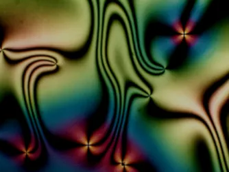
Defects can be easily detected in a nematic, when viewed under crossed polariz-ers. Point defects appear as black brushes, called schlieren brushes, and disclination lines as black threads [4]. The black regions are a consequence of the optical extinc-tion that occurs when the alignment of the molecules has different direcextinc-tion than the polarization vector. In this case there is no transmission of light. Knowing the orientation of the molecules at the black regions allows one to infer the presence of the topological defects. A typical nematic texture, called schlieren texture, is shown in Fig. 1.2. It exhibits regions with brushes and threads resulting from point defects and disclination lines respectively.
Figure 1.2: The schlieren texture. Nematic observed under crossed polarizers. The black brushes correspond to topological point defects. Microphotograph courtesy of Oleg D. Lavrentovich, Liquid Crystal Institute, Kent State University.
When chiral molecules, i.e. molecules with no mirror symmetry plane, are added to the nematic phase, the chirality expresses itself by favouring a periodic twist of the orientation in the direction perpendicular to the molecular axes (see Fig. 1.3 (a)). The resultant phase receives the name of cholesteric, or chiral nematic. The molecular orientation in the cholesteric phase describes an helical shape. The distance for which the orientation of the molecules rotates by 2π is the periodicity of the cholesteric and it is called the cholesteric pitch (see Fig. 1.3 (b)).
The pitch of the cholesteric is usually of the order of a few hundred nanometres. Because of their periodic structure, cholesterics give rise to visible light Bragg scat-tering. Cholesterics are therefore ideal for optical applications. On the other hand, the pitch is also very sensitive to temperature, pressure, chemistry, etc. Since the change of these conditions provokes a change of color of the material, cholesterics make for very accurate sensors.
(a) (b)
Figure 1.3: The cholesteric phase. (a) Molecular orientation twisting in space in a cholesteric phase. (b) The molecular orientation twists with a periodicity designated by pitch P . The pitch is the distance over which the orientation twists by a complete 2π turn. A π turn corresponds to half a pitch P2. Figure reproduced from [6].
Although their great potential for optical applications is nowadays widely recog-nised, the study of liquid crystals remained solely of academic interest until 1962 [8]. The first use of a nematic in a display device changed this picture. The Liquid Crystal Display (LCD) technology revolutionized the display industry. Cathode ray tube displays gave way to flat panels and new smaller devices, such as laptops, tablet computers and smartphones, were made possible.
The first, and simplest, model of a liquid crystal display is known as the twisted nematic (TN) display. The TN display is still the most commonly used for everyday items like watches and calculators [9].
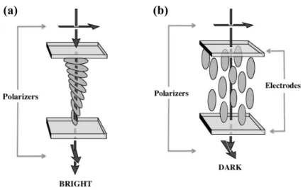
The device consists of a nematic liquid crystal sandwiched between two glass plates. Each of the glass plates is treated to fix the orientation of the nematic on its surface. The orientation at the top is perpendicular to the orientation at the bottom. In between the top and bottom plates, the nematic assumes a twisted configuration (see Fig. 1.4 (a)). This structure is similar to the cholesteric state, and sometimes a small amount of a chiral material is added to ensure a uniform twist. A polarizer is put outside each of the glass plates so that the direction of polarization matches the direction of the molecules on the glass surface. When the light passes through the cell in this twisted state, the direction of polarization is rotated in the same way as the molecular orientation. Therefore, the light reaches the bottom polarizer with a polarization parallel to it and it is transmitted. This is called the transmissive state because the cell gives a bright output. If a field is applied, with an intensity superior to the necessary threshold for the Fredericks transition [5], the molecules align with the field and the polarized light is no longer rotated (see Fig. 1.4 (a)). As a result, the light reaches the bottom polarizer with a direction perpendicular to
it, and it is not transmitted. The cell appears dark.
(a) (b)
Figure 1.4: The twisted nematic display. (a) The transmissive or bright state. The configuration of the nematic in between the two glass plates is twisted. The direction of polarization of the light rotates with the orientation of the nematic, reaching the bottom polarizer parallel to it. (b) The dark state. The nematic has the orientation of the electric field. The direction of polarization of light is not rotated, and it reaches the bottom polarizer perpendicular to it. Figure reproduced from Fig. 6 of [8]
The twisted nematic display takes advantage of the nematic properties of sur-face anchoring, elasticity and interaction with external fields. These allow the switch between the two different configurations, alternating between the bright and dark states, to form the image. The geometry of the apparatus is relatively simple, with the nematic confined in between two flat glass plates. Regardless of its geometri-cal simplicity, the development of the LCD was the basis for a multi-billion dollar industry [10].
The interfacial ordering of liquid crystals continues to be a topic of research [11]. Apart from its fundamental interest, there are also potential implications to the creation of self-assembling metamaterials, and liquid crystal based responsive materials, such as bio-sensors [12].
When the confining surfaces or interfaces are curved, the number and complex-ity of possible configurations increases greatly, as do the parameters that allow the switching between them. For an ordered medium on a curved surface, the geometry plays an important role. The curvature itself might influence the state of alignment of the liquid crystal. The curvature imposes a strain that can be accommodated in different ways, depending on the elastic constants of the medium as well as on the elastic anisotropy [13]. On the other hand, there are the topological constraints.
There is a fundamental topological theorem, due to Poincaré and Hopf [14] that im-poses the presence of topological defects depending on the topological characteristics of the surface.
Rather than being just a disturbing presence in the equilibrium configurations, the defect structures can actually be of relevance in material science and engineering, as proposed in [15]. The basic idea is to use spherical liquid crystal droplets, or colloids coated by liquid crystals, as building blocks for self-assembling materials. The liquid crystal configurations will inevitably include defects. Since defects possess different physical properties, they can be functionalized with target molecules to promote directional interactions [16]. In this sense, the number of defects acts as a valence of the particle [17]. The control of the number of defects and their positions, by geometrical or external parameters, can allow to target different architectures.
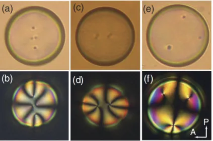
This possibility has triggered extensive experimental and computational study of the nematic configurations inside spherical nematic droplets and spherical nematic shells [18, 19]. The configurations on nematic shells have been found to depend on the boundary conditions [20, 21] and thickness of the shell [22, 23, 24, 25]. Figure 1.5 shows three types of thin nematic shells with variable number of defects. In this case, the number of defects was controlled by the thickness and thickness anisotropy of the shell.
Figure 1.5: Three types of thin nematic shells commonly observed, distinguished by the number and type of defects: (a), (b) four defects; (c), (d) two defects; (e), (f), three defects. Figure reproduced from Fig. 3 of [23].
The development of novel experimental techniques has allowed the production of droplets with different topologies. In order to overcome the surface tension that favours the spherical shape of the droplets, a continuous viscous phase is used to
provide a mold [26]. With this technique, it is possible to produce toroidal droplets and droplets with multiple handles. The procedure consists of injecting the liquid crystal through a thin needle into a rotating bath that contains the viscous phase (see Fig. 1.6 (a)). The angular speed of the bath and the speed of injection of the liquid crystal define the geometrical parameters of the droplet. When the rotation completes one full turn, the process stops and the outside medium stabilizes the droplet (see Fig. 1.6 (b)).
Figure 1.6: Experimental technique for stabilizing toroidal droplets. (a) Injection of the liquid crystal into the rotating viscous bath. A curved jet is formed. (b) Once the jet concludes one full revolution, the toroidal droplet is closed. Figure reproduced from Fig. 6 of [27].
Studying the behaviour of ordered media confined inside such non-trivial geome-tries is pivotal to understand the role of the topological constraints in the liquid crystal configurations. Also, by varying the geometry of the droplets, more textures are made available, with different optical properties and possible applications to photonic devices.
The toroidal shape has a particular topological significance. For a toroidal sur-face, the Poincaré-Hopf theorem allows the existence of configurations without topo-logical defects. From a fundamental point of view, such configurations allow a deeper study of the curvature effects on the observed textures. The curvature together with the elasticity of the material induce configurations that could not be predicted just by the assumption of topological constraints [28]. This is the case of the toroidal nematic droplet, for which theoretical [29] and experimental [30] studies have found that, when a nematic is confined inside a toroidal droplet, there is a spontaneous breaking of the mirror symmetry, with a persistent chiral twisted state along the torus.
a new length scale to the problem. The intrinsic periodicity of the cholesteric, the pitch, is one extra parameter that can be adjusted to define the stability regime of each possible configuration. Also, the set of possible textures increases. This was first exemplified in the theoretical studies of cholesterics in cylindrical cavities [31, 32]. The equilibrium configurations depend on the radius of the cylinder and on the elastic constants, just like the nematic, but also on the natural pitch of the cholesteric.
Spherical cholesteric droplets have also been reported in the literature. The studies confirm that the ratio between the pitch of the cholesteric and the radius of the sphere is one of the main parameters affecting the configuration [33]. The configurations found are more diverse than the nematic ones, with an internal defect structure that is only possible due to the natural spontaneous twist of the cholesteric [34].
The main goal of this thesis is to expand the study of the confinement of cholester-ics to the toroidal droplet. The topology of the cholesteric is identical to the one of the nematic. Therefore, for a cholesteric it is still possible to have configurations with no topological defects. This allows us to investigate how the curvature of the system affects the natural periodicity of the cholesteric and how the relation be-tween the pitch and the geometrical parameters of the torus define the equilibrium configurations.
We start by introducing, in Chapter 2, the theoretical background for the mod-elling of the cholesteric liquid crystal. We present the tensorial order parameter and construct the free energy that describes the symmetries of the system. We also introduce the concept of topological defects and the formal statement of the Poincaré-Hopf theorem, discussing its implications for different curved surfaces.
In Chapter 3, we briefly describe the numerical methods used to obtain the equilibrium configurations of the cholesteric liquid crystal. We deduce a system of differential equations that allow us to assume cylindrical symmetry on the system and calculate only on a two-dimensional cross-section. Then, we discuss the advan-tages and disadvanadvan-tages of our numerical techniques for the minimization of the free energy of the system.
We present our numerical results in Chapter 4. This Chapter is divided in three parts, each one corresponding to a different curved system. We use different systems to isolate the effects of curvature on the cholesteric. We find that the curvature influences the orientation of the cholesteric close to the surface. This effect propagates through the configuration and it is responsible for distorting the periodicity of the cholesteric inside the toroidal droplet.
Mesoscopic Modeling
2.1
Order Parameter
The anisotropic molecules in nematic and cholesteric phases display long range ori-entational order. The molecules align, on average, along a common direction, de-scribed by a unit vector called director [4]. In nematics, the director varies in space due to external fields and constraints in the system (e.g. boundary conditions). In the case of cholesterics, the director twists spontaneously, describing an helicoidal shape. Nematics and cholesterics show a higher degree of order than the isotropic liquid [7]. To put this in a quantitative basis, it is necessary to define an order pa-rameter that is non-zero in the liquid crystal phase and that vanishes, for symmetry reasons, in the isotropic phase.
The director n(r, t) at position r and time t is defined as the ensemble average of molecular orientations u(r, t) within a given volume segment or, due to ergodicity, as the time average of a single molecule orientation at a given position. The orientations n(r, t) and −n(r, t) are equivalent. This is due to the fact that the molecules either have a center of inversion or, if they do not, they have equal probability of pointing parallel or anti-parallel to any given direction [7].
Because of thermal fluctuations, the molecules are not perfectly aligned to the director. Instead, there is a distribution of molecular orientations [5]. From this distribution, one can know the state of alignment of the molecules and extract a degree of order for the system.
In a reference frame where the z-axis is chosen to coincide with the direction of n, the molecular orientations relative to the director are specified by the polar and azimuthal angles (θ, ϕ), as depicted in Fig. 2.1. The distribution function for the orientations is then g(θ, ϕ). g(θ, ϕ)dΩ represents the probability of finding molecules
2.1. Order Parameter
Figure 2.1: Polar and azimuthal angles, (θ, ϕ), that define the orientation u of the molecules, relative to the director n.
in a infinitely small solid angle dΩ = sin θdθdϕ around the direction (θ, ϕ) [5]. In this work, we shall only consider uniaxial phases, i.e. with a single preferred axis around which the system is rotationally invariant [7]. For uniaxial phases, there is complete cylindrical symmetry around n and, therefore, the distribution function is independent of the angle ϕ, g(θ, ϕ) = g(θ). Also, due to the symmetry n = −n,
g(θ) = g(π − θ). Thus, for this distribution function, the average of the scalar
product between the molecular orientations u and n is [5].
⟨u · n⟩ = ⟨cos θ⟩ =
∫
g(θ) cos θdΩ = 0 . (2.1)
Here, ⟨.⟩ represents the ensemble average.
Given that the average projection of the molecular orientations u onto the direc-tor is equal to zero, this quantity does not provide any information about the state of alignment in the liquid crystal phase.
To characterize the order, one must resort to higher multipoles. The first multi-pole giving a non-zero result is the quadrumulti-pole
S = 1 2⟨3 cos 2 θ− 1⟩ = ∫ g(θ)1 2 ( 3 cos2θ− 1)dΩ . (2.2)
S is called the scalar order parameter, with θ representing the angle of deviation
from the director.
The values of S lie in the interval[−12, 1]. The value S = 1 represents a perfectly ordered state, S = −12 represents an arrangement where the molecules are aligned
perpendicular to the director (which happens for disk-like molecules), and the value
S = 0 corresponds to a perfectly disordered, or isotropic, state. Ergo, S distinguishes
between the isotropic and anisotropic phases.
The state of the system is completely specified by the knowledge of the direc-tor n and the scalar order parameter S. These two quantities complement each other, providing information about the direction of alignment of the molecules and the degree of order around that direction. S and n can be combined in a single order parameter. Because of the inversion symmetry between n and −n, any order parameter must be an even function of n. Therefore, a vector order parameter is insufficient. A more suitable order parameter can be introduced as a second-rank tensor. The tensorial order parameter is defined, for an uniaxial nematic, as
Qαβ =
S
2 (3nαnβ − δαβ) , (2.3) where α, β = x, y, z and δαβ is the Kronecker delta.
By definition, and as a consequence of the properties of the director, the Q tensor is symmetric Qαβ = Qβα and traceless Qαα = 0. 1 Also, in the isotropic phase the
order parameter is zero as expected, Qαβ,iso = 0. The scalar order parameter S
is the largest eigenvalue of Q, with corresponding eigenvector n. The other two eigenvalues are equal to −S2 and have corresponding eigenvectors perpendicular to n. Note that if biaxiality is considered, the definition of the order parameter is
Qαβ = S2 (3nαnβ− δαβ) + B2 (lαlβ − mαmβ) [35], where n, l, and m form a local
orthonormal triad. The direction of maximum orientational order is still associated with n, but the cylindrical symmetry around n is broken. Even if the molecules have cylindrical symmetry, biaxiality may arise from spatial non-uniformities on the plane perpendicular to n and results in a parameter B ̸= 0. For non-zero biaxiality, the Q tensor has three different eigenvalues: S, −12S + B, and−12S− B.
Because it does not deal with the director n and the scalar order parameter S independently, the tensorial approach with order parameter Q is appropriate for the description of samples with spatially varying degree of order S = S(r). Therefore, the tensorial approach is needed in many problems involving the interaction with surfaces, and when topological defects are present.
1The number of components of a general 3× 3 second-rank tensor is 9. The Q tensor however, being symmetric and traceless, has only five independent components. Thus, the Q tensor is often explicitly represented as Q =
qq12 qq24 qq35 q3 q5 −(q1+ q4)
, with q1, q2, q3, q4 and q5 being the only independent components. This form is useful in the calculations as it reduces the number of variables to solve for.
2.2. Landau-de Gennes Model
2.2
Landau-de Gennes Model
Once the appropriate order parameter of the system is defined (here the Q tensor), one can construct a free energy functional F for nematic and cholesteric liquid crystals. The free energy functional is an integral over the volume of the sample of a free energy density f , expressed as a function of Q. The free energy density is made of two contributions: ford, a Landau free energy that models the transition
between the isotropic phase and the ordered liquid crystal phase, and felas, an elastic
contribution that penalizes distortions from the preferred alignment
F =
∫
[ford+ felas] dV . (2.4)
2.2.1
The nematic-isotropic transition
In the spirit of Landau theories, one can assume that the free energy density
ford(P, T, Q) is an analytic function of the order parameter tensor Q. Here, P
repre-sents the pressure and T the temperature. For thermotropic liquid crystals, the tem-perature is the main parameter driving the transition between different mesophases. Near the transition temperature, and to the extent that Q is a small parameter, the free energy density ford(P, T, Qαβ) may be expanded in a power series of the order
parameter.
The ordered phase is invariant under uniform rotations of the group O2 on the
plane perpendicular to the director. Rotations outside of this plane alter the director. However, because the direction of alignment is arbitrary in space, the state generated by such rotation corresponds to an equivalent system, which should have the same free energy. This symmetry imposes that ford(P, T, Qαβ) must be invariant under
the group SO(3) of all rotations [7]. Since Qαβ transforms like a tensor under the
rotation group, the terms of the expansion allowed by symmetry must be scalar functions of Qαβ. The minimal free energy volume density ford needed to model the
nematic-isotropic transition reads
ford = fiso+ 1 2A QαβQβα+ 1 3B QαβQβγQγα + 1 4C (QαβQβα) 2 , (2.5)
which is correct to fourth order in Qαβ. Summation over repeated indices is assumed.
fiso is the free energy density of the isotropic phase. The first order term in this
expansion would simply be the trace Qαα which is, by definition, equal to zero.
Thus, there is no linear term in the free energy. As a consequence of this symmetry, the state of minimum energy has a state of zero Qαβ, that is to say, isotropic. There
is just one distinct invariant of the second, third, and fourth orders. Other forms (such as QαβQβγQγδQδα) are strictly proportional to the ones included in (2.5) for
a 3× 3 symmetric and traceless tensor [7].
Assuming an uniaxial nematic, the trace invariants of the order parameter tensor simplify to QαβQβα = 3S
2
2 , and QαβQβγQγα = 3S3
4 . Thus ford can be rewritten as a
function of the scalar order parameter S:
ford = 3 4A S 2 +1 4B S 3 + 9 16C S 4 . (2.6)
The energy fiso of the isotropic phase has been taken as the zero of the energy scale.
The coefficients A, B, and C are nematic material properties and are, in general, functions of the pressure P and temperature T . In the nematic phase, both A and
B are negative and only C > 0 ensures that the free energy density functional is
bounded from below.
Typical to Landau-type theories, this model equation of state predicts a phase transition near the temperature where A vanishes. It is normally assumed that
A has the form A = a(T − T∗), where T∗ is the supercooling temperature [7]. The coefficients B and C need have no particular properties near T∗, and will be regarded as constants. Under this assumption, A is the only pre-factor having a temperature dependence and, therefore, drives the nematic-isotropic transition. Typical values for 5CB, a nematic commonly used in experimental studies, are
A =−0.1694MJ/m3, B = 0.816M J/m3, C = 0.45M J/m3.
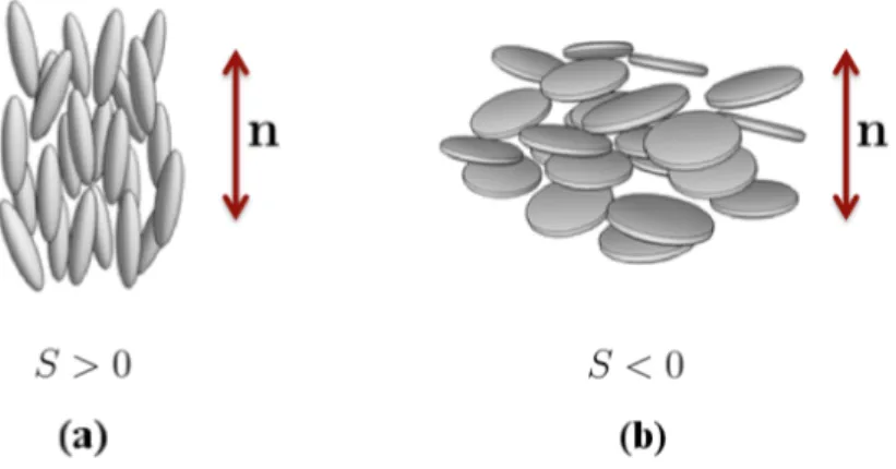
The nematic-isotropic transition is of first order [7]. This is related with the meaning of the sign of the scalar order parameter S. States with S > 0 correspond to rod-like configuration where the molecules have their long axis aligned with the director, while states with S < 0 correspond to a disk-like configuration where the molecules are aligned perpendicular to the director. The two situations are depicted in Fig. 2.2. The states with S > 0 and S < 0 are not related by any symmetry operation. Thus, there is no reason for them to have the same energy. The lack of symmetry between states with positive and negative scalar order parameter is the basis of the first order transition [7] and it is modelled in the free energy by the third order term S3. The role of this term is exactly to break the symmetry between
states with S > 0 and S < 0.
The interpretation of the Landau expansion terms in expression (2.6) for the free energy density fordis now clear: first term drives the transition, second term ensures
asymmetry by breaking the S > 0 to S < 0 invariance, and the third term bounds the values of ford from below.
2.2. Landau-de Gennes Model
Figure 2.2: (a) Nematic alignment for rod-like molecules. Molecular long axis are aligned parallel to the director, corresponding to a positive value of the scalar order parameter S > 0. (b) Nematic alignment for disk-like molecules. The director is perpendicular to the molecules, corresponding to a negative value of the scalar order parameter S < 0.
equilibrium scalar order parameter Seq in terms of the material parameters
Seq(A, B, C) = 0, T > TN I 1 2 [ −B 3C + √(B 3C )2 − 8A 3C ] , T < TN I, (2.7)
where TN I is the nematic-isotropic transition temperature.
It is useful to rescale the energy by defining the quantities [36]
˜ Qij = 6C B Qij, (2.8) ˜ ford = 242c3 B4 ford. (2.9)
Also, a dimensionless temperature τ can be introduced so that the nematic phase is stable for τ < 1
τ = 24AC
B2 . (2.10)
With the previous definitions, the rescaled free energy as a function of the rescaled scalar order parameter is given by
˜
and the equilibrium scalar order parameter for the nematic phase becomes ˜ Seq = 3 4 ( 1 + √ 1− 8 9τ ) . (2.12)
The minus sign, explicitly expressed in Eq. (2.11), comes from the breaking of the invariance between ˜S > 0 and ˜S < 0.
The characteristics of the ˜ford free energy density for the different temperature
regimes, including the metastability limits, are presented in Fig. 2.3. The isotropic-nematic transition occurs at the critical temperature τc, for which the ordered ˜S = 0
and disordered ˜S ̸= 0 states are equally probable. Above the transition temperature,
and below the superheating temperature τ∗∗, the nematic phase is metastable and the isotropic phase is stable, corresponding to the lowest value of the free energy. Above the superheating temperature τ∗∗, the free energy has one only minimum for
˜
S = 0. Below the transition temperature τc, and above the supercooling temperature
τ∗, the free energy has two minima: the isotropic state, which is metastable, and the ordered state, which is stable. Below the supercooling temperature τ∗, the only minimum of the free energy corresponds to the nematic phase. The transition is of first order, as can be seen by the energy barrier between the two states that minimize the free energy.
(a) (b)
Figure 2.3: Free energy density ˜fordas a function of the scalar order parameter ˜S for
different temperatures τ , for the isotropic-nematic transition. The transition is first order. Note the limits of metastability for supercooling (τ∗) and superheating (τ∗∗). (a) High temperature regime. For τ above the superheating temperature τ∗∗ only the isotropic phase ( ˜S = 0) is stable. When the temperature decreases to τ∗∗, the nematic phase becomes metastable. On the transition temperature τc, the isotropic
and nematic phases are equiprobable. The nematic phase is stable below τc. (b)
Low temperature regime. The isotropic phase is no longer metastable below the supercooling temperature τ∗.
2.2. Landau-de Gennes Model
2.2.2
Elastic energy
Because the molecules tend to align along an average direction, the lowest energy state for the nematic phase is homogeneously oriented throughout the sample. Any deformations of this uniform director field are penalised with an increase of the free energy. Therefore, nematics act as effective elastic materials when their orienta-tional ordering is subjected to spatial variations. If the deviation in the molecular orientations varies slowly in space on the molecular distance scale, one is able to describe the distortion of the liquid crystal with a continuum elastic theory. Here the deformations are not the changes of the position of neighbouring points as in solids, but are the changes in the orientation between two neighbouring points.
Three basic types of deformations can be identified: splay, twist and bend. Each one corresponds to a non-vanishing term in the derivatives of the director n. The representation of the three basic deformations is shown in Fig. 2.4.
(a) (b) (c)
Figure 2.4: Elastic deformation modes: (a) splay, (b) twist, and (c) bend.
The free energy that models these deformations can be constructed by expanding around the uniform state in derivatives of the director field. Given that the charac-teristic dimensions of the deformations are large compared to molecular dimensions, the spatial derivatives of the director ∂αnβ are small quantities. It usually suffices
that only first and second order terms in the expansion of the free energy density are retained. Thus, the free energy density can be written generally as [37]
felas = Kαβ ∂αnβ+ Kαβγδ (∂αnβ) (∂γnδ) + Kαβγ ∂α∂βnγ, (2.13)
where the indices α, β, γ, δ represent the cartesian coordinates.
Again, the free energy must be invariant under the symmetry operations that leave the nematic phase unchanged. Thus, for a nematic, the energy density felas
operations n→ −n and x → −x. The tensors Kαβ, Kαβγ, and Kαβγδ must be
com-posed of all possible invariants constructed with the director nα, the Kronecker delta
function δαβ and Levi-Civita tensor εαβγ, that are allowed by symmetry. Analysing
all the possibilities for the Kαβ, Kαβγ, and Kαβγδ tensors that are compatible with
the symmetries of the free energy, and excluding those that can be integrated as surface terms, one can identify the following independent terms
(∂αnα) (∂βnβ) = (∇ · n)2, (2.14)
(∂αnβ) (∂βnα) = (∇ · n)
2
+ (n· ∇ × n)2+ (n× ∇ × n)2, (2.15)
nαnβ(∂αnγ) (∂βnγ) = (n× ∇ × n)2. (2.16)
These invariants can be grouped to construct the Frank-Oseen free energy density, where the basic deformations (Fig. 2.4) are easily identified.
[ felasF O]nem= 1 2K1(∇ · n) 2 +1 2K2(n· ∇ × n) 2 +1 2K3(n× ∇ × n) 2 . (2.17)
K1, K2, and K3 are the elastic constants for splay, twist, and bend deformations,
respectively.
Cholesteric liquid crystals are made of chiral molecules and therefore for this type of liquid crystal there is no mirror symmetry x→ −x. This means that there is one more term allowed by the symmetry
εαβγnγ∂αnβ = n· (∇ × n) . (2.18)
Introducing the term (2.18) in the elastic free energy, one finds the elastic free energy density for the colesteric
[ felasF O]chol = 1 2K1(∇ · n) 2 +1 2K2(n· ∇ × n − q0) 2 + 1 2K3(n× ∇ × n) 2 , (2.19) q0 = 2πP
0, with P0 the cholesteric pitch, this is, the length at witch the director turns
by 2π. q0 vanishes for a nematic.
The Frank-Oseen free energy can be extended to include the mixed terms f13
[38] and f24 [39], which are also allowed by symmetry.
f13 = K13▽ · [n(▽ · n)] (2.20)
f24 = −K24▽ · [n(▽ · n) + n × (▽ × n)] (2.21)
2.2. Landau-de Gennes Model
respectively. The f13 and f24 terms are designated divergence volume density terms
because they can be transformed into surface terms by the direct application of the Gauss theorem. For that reason, it is considered that their effect on the bulk behaviour of the liquid crystal can be treated with a renormalization of the sur-face anchoring. We will not consider the contribution of the mixed terms in the development of our model.
The vectorial approach to the construction of the elastic free energy density allows a direct characterization of the three elastic distortion modes. However, when describing samples where not only the director n varies in space but also the scalar order parameter S depends on the position, the tensorial order parameter
Qαβ is needed. In the tensorial approach, the spacial derivatives are also assumed
to be small and the free energy density is expanded into series over invariant terms of Qαβ and ∂αQαβ. The procedure to construct the free energy density is the same
as for the vectorial approach, one needs to find quantities that are invariants under the same symmetry operations to as the free energy.
The simplest elastic free energy that models all the same distortions as the Frank-Oseen free energy is:
felas = 1 2L1∂γQαβ∂γQαβ+ 1 2L2∂βQαβ∂γQαγ+ 1 2L3Qαβ∂αQγδ∂βQγδ+2L1q0εαδγQαβ∂βQγβ (2.22) where L1, L2 and L3 are tensorial elastic constants, xα are Cartesian coordinates,
and summation over repeated indices is assumed. Three elastic constants are intro-duced in order to account for the three basic deformation modes. Again, the term proportional to q0 is only present for the cholesteric phase and it vanishes in the
nematic. The Li are independent of the degree of order S and should be interpreted
as the direct strength of the inter-molecular interactions.
The relation between elastic constants in the vectorial and tensorial frameworks is obtained when Qαβ in the free energy density (2.22) is replaced by the uniaxial
nematic definition Qαβ = S2 (3nαnβ− δαβ). By making use of the identities nαnα = 1
and nα∂nxγα = 0, the Frank-Oseen free energy, in terms of the director n, is recovered,
given the correspondences [40]
L1 = K3+ 2K2− K1 9S2 , (2.23) L2 = 4(K1 − K2) 9S2 , L3 = 2(K3 − K1) 9S2 .
Elastic free energy volume densities are complex spatially dependent functionals when used with all three elastic constants. A common approximation to simplify the free energy density functional is to use the one elastic constant approximation which sets K1 = K2 = K3 and, consequently, L1 = L, L2 = L3 = 0. Typical values for the
elastic constants in 5CB are L1 = 6× 10⁻¹²J/m and L2 = 0J/m. (We assume the
nematic 5CB material parameters in order construct a simple cholesteric model in which we allow a spontaneous twist.) Within the one constant approximation, the restoring forces that oppose the three basic deformations have equal strength. The free energy felas is then written as:
felas =
1
2L∂γQαβ∂γQαβ+ 2Lq0εαδγQαβ∂βQγβ (2.24)
The ratio of the two energy contributions in the Landau-de Gennes free energy introduces a spatial scale for the variation of the nematic degree of order. This char-acteristic length scale is referred to as the nematic correlation length ξ. Typically,
ξ is of the order of a few nanometres, and it is related to the material parameters
by the expression [36]
ξ2 = L18C
B2 . (2.25)
The correlation length plays a very important role in the discussion of topological defects as it roughly determines their size.
Rescaling all the positions by ˜r = rξ, and the tensorial order parameter and free energy density according to (2.9), the elastic free energy takes the form
˜ felas = 1 3 + 2κ ( ˜ ∂γQ˜αβ∂˜γQ˜αβ + κ ˜∂βQ˜αβ∂˜γQ˜αγ ) , (2.26) where κ = L2
L1. The one elastic constant approximation corresponds to setting κ = 0.
2.3
Surface anchoring
Interfaces with solid, liquid or gas materials affect liquid crystal ordering by imposing a preferred degree of order and a preferred molecular orientation. Such behaviour is usually referred to as anchoring. Three typical situations are: i) homeotropic anchoring, where the preferred, or "easy", on average orientation corresponds to n normal to the interface, ii) planar anchoring, where the preferred average orientation corresponds to n lying in one particular direction parallel to the interface, and iii) planar degenerate anchoring, where all the planar orientations for n are equivalent
2.3. Surface anchoring
easy directions.
Uniform, or non-degenerate, surface anchoring is modelled by using a Nobili-Durand [41] like surface free energy density functional fsurf:
fsurf = 1 2W ( Qαβ− Q0αβ )2 , (2.27)
where W is the uniform surface anchoring strength and Q0αβ is the surface preferred order parameter tensor. fsurf penalizes all deviations of Qαβ from Q0αβ. Therefore
Q0αβ imposes not only the preferred direction at the surface, the easy axis, but also the surface degree of order. Because fsurf is proportional to the sum of the squares
of the components of Q− Q0, it has, for W > 0, a unique minimum for Q = Q0.
Planar degenerate anchoring describes the tendency of a substrate to favour the common alignment of the molecules along any direction parallel to its surface. To model such situation, it is necessary to include terms of order higher than two. Going up to fourth order ensures that the surface free energy is bounded from below. This is also the lowest order for the bulk free energy to describe correctly the nematic-isotropic transition. Such degenerate surface functional was introduced by Fournier and Galatola [42] fsurfdeg = W1 ( ˜ Qαβ − ˜Q⊥αβ )2 + W2 ( ˜ QαβQ˜βα− 3 2S 2 surf )2 , (2.28) where W1 and W2 are two surface anchoring constants, Ssurf is the surface-preferred
degree of order, ˜Qαβ = Qαβ+ Ssurf
2 δαβ, and ˜Q⊥αβ = PαγQ˜γδPδβ, with Pαβ = δαβ−νανβ
and να the surface normal. Typical values for the anchoring constants are Wi =
0.01J/m2. The first term imposes that ˜Q
αβ coincides with its projection on the
substrate ˜Q⊥αβ. The second term addresses the degree of order and imposes that the trace of the square of ˜Qαβ coincides with SSurf2 . These two conditions are necessary
and sufficient to obtain the condition of planar degenerate anchoring.
The rescaling relations used in the previous sections simply rescale the anchoring constants by ˜Wi = 16WB2iξC.
The free energy that describes the order ford, the elastic free energy felas, and
the anchoring free energy fsurf are combined into a single functional F, as defined
in Eq. (2.4). The Landau-de Gennes model is the central phenomenological model for nematic and cholesteric liquid crystals at micron and sub-micron mesoscale as it incorporates both elasticity and spatial variation of the nematic degree of order. The equilibrium configuration of the nematic or cholesteric in an arbitrary geometry is obtained by the minimization of this free energy in the volume of the sample. This is
the approach followed in the present work. We use numerical methods to discretize the sample space and minimize the free energy, obtaining the stable (or, at least, metastable) configurations of the confined cholesteric.
2.4
Topological Defects
The Landau-de Gennes free energy models the orientational ordering of the molecules in the nematic phase. As a result of this ordering, the minimum energy configuration for a nematic in bulk is uniformly aligned. The preferred direction of ordering is, however, arbitrary and it is only fixed in practice by an external field or by interac-tion with a surface. Distorinterac-tions from the homogeneously aligned state are penalised by an increase of the free energy. Although configurations with distortions have a higher free energy, they are the lowest energy state in situations where the alignment with boundary conditions and external fields has to be obeyed.
When the liquid crystal is confined, there may not be a configuration that satisfies the boundary conditions, while including only continuous distortions. In such cases there is the nucleation of topological defects, i.e., singularities in the orientational field.
Topological defects appear in physics as a consequence of broken continuous symmetry and they have different names depending on the symmetry that is broken and the particular system in question. Defects in the orientatonal order, such as in nematic or cholesteric liquid crystals, are called disclinations [7]. The defects are topological when they cannot be removed by a continuous deformation of the order parameter. This is different from what happens with the elastic distortions. A configuration that exhibits elastic distortions without singularities can be returned to the aligned state by a sequence of distortions in which the director at each point changes by an infinitesimal amount relative to the previous configuration. An at-tempt to align the molecules in a configuration including topological defects would imply a discontinuous change of the orientations at some point.
A topological defect is characterized by a small core region where the order is destroyed and a far field region where the orientation varies slowly in space. This singularity could be removed by cutting a hole of radius ξ0 out of the material,
around the core region. An alternative approach is to have the magnitude of the scalar order parameter go to zero at the core and rise to its equilibrium value at a radius ξ0. Since the order parameter is zero at the origin, the director is no
longer defined there, and the mathematical singularity has been removed. This is an argument for the use of the tensorial order parameter in situations that involve
2.4. Topological Defects
topological defects. At the core, the director is not defined but the tensor Qαβ has
the value Qαβ = 0 because S = 0. In this sense, the core of the defect is like a small
region of isotropic phase and has dimensions of the correlation length ξ, since this is the scale of variation of the degree of order.
Topological defects have the property that its presence can be determined by measurements of an appropriate field on any surface enclosing its core. For nematics and cholesterics, this is the director field. In 2D, the number of times that the director completes a rotation by an angle of 2π measured on any closed circuit around the defect core is the topological charge m. Because the circuit must be a closed loop, the topological charge may only take on a discrete set of values. In nematics and cholesterics, due to the equivalence between positive and negative directions of the director, the topological charge may assume half integer numbers. The sign of this charge is positive if the director rotates in the direction of circulation of the path and negative otherwise.
(a) (b)
(c) (d)
Figure 2.5: Schematics of the director field in configurations with topological defects with charges m = 1 (a), m = −1 (b), m = 12 (c), and m = −12 (d). The grey rods represent the director orientation and the red dots represent the cores of the defects.
Defects appear in the equilibrium configuration of nematics and cholesterics be-cause they cannot be removed without making discontinuous changes in the config-uration. They are topologically stable. However, their presence increases the free energy. This increase in the free energy is divided into two contributions, one from the decrease of order at the core of the defect, and the second from the far field
elastic distortions. For a defect in the plane, the total free energy is, in the one elastic approximation K1 = K2 = K3 = K[7] E = Ecore+ Eelastic (2.29) = πKm 2 2 + πKm 2 ln ( R ξ0 ) ,
where R is the dimension of the sample and ξ0 the dimension of the core of the
defect.
In cholesteric liquid crystals, the director twists periodically on a direction per-pendicular to itself. Because of this escape to the third dimension, disclinations in cholesterics can be singular or non-singular [34]. We shall distinguish three classes:
λm, τm, and χm (see Fig. 2.6). In the λ and τ disclinations there is no twist of the director along the disclination. λ disclinations are non-singular and τ disclinations are singular. The director twists along the χ disclination, resulting in planes with and without singularities.
Figure 2.6: Schematic representation of cholesteric disclination lines λm, τm, and
χm with various topological charges m. The director is shown with blue cylinders
and the red spheres represent regions with lower order parameters. The core of the
χ disclination is drawn as a black line. Figure obtained from Fig.1 of [34].
Curved geometries introduce new constraints to the system, since the packing is not the same as in a flat geometry. Let us consider, for illustration, the canonical example of the packing of hexagons. On a plane, it is possible to arrange hexagonal
2.4. Topological Defects
cells in a honeycomb pattern, filling the space with no frustrations as in Fig. 2.7(a). However, on the surface of a sphere, it is not possible to do the same. A known example of a pattern that can fill such curved space is the soccer ball with 12 pentagon panels dispersed among hexagons, as shown in Fig. 2.7(b).
(a) (b)
Figure 2.7: Packing of hexagonal cells in a flat space (a) and on the surface of a sphere (b). Figure obtained from Fig.1 of [27].
The flat space and the surface of a sphere have different topologies. The topo-logical shape of a space is described by a topotopo-logical invariant called the Euler characteristic χ (or Euler-Poincaré characteristic). The Euler characteristic can be given, for closed surfaces, by the expression [43]
χ = 2 (1− g) , (2.30)
where g is the genus or number of handles of the surface. For instance, the sphere has genus g = 0 and Euler characteristic χ = 2. The torus has genus g = 1 and Euler characteristic χ = 0.
Analogously to the packing of geometrical shapes like the hexagons, we can align rods that represent the director field. When we align rods on a curved surface there is a topological constraint that fixes the net charge of topological defects that must be present on the surface. This is expressed in the Poincaré - Hopf Theorem [43] stating that the sum of the topological charges must be equal to the Euler characteristic of the surface
∑
i
mi = χ = 2 (1− g) , (2.31)
where mi is the topological charge of each defect.
In particular, it is impossible to align rods smoothly on a sphere without having any sources or sinks (see Fig. 2.8). Aligned configurations on the surface of a sphere