0103 - 5053 $6.00+0.00
A
r
ti
c
le
* e-mail: [email protected]
An Automatic Flow-Batch Standard-Addition Method for Sodium Determination in
Alcohol Fuel by Flame Photometry
Luciano F. de Almeida, Valdomiro L. Martins, Edvan C. da Silva, Pablo N. T. Moreira and Mario Cesar U. Araujo*
Departamento de Química, CCEN, Universidade Federal da Paraíba, CP 5093, 58051-970 João Pessoa - PB, Brazil
A agência brasileira que regulamenta a produção e comercialização de álcool combustível estabelece que a concentração de sódio deve ser determinada usando a fotometria de chama e curva analítica construída com soluções padrão preparadas em uma matriz que se assemelhe às amostras. Todavia, essa metodologia pode produzir resultados inexatos porque o álcool combustível apresenta uma variabilidade significativa na composição de matriz e, conseqüentemente, no efeito de matriz. Esse problema pode ser contornado usando o método por adições de padrão (MAP), porém o MAP é lento e trabalhoso quando realizado manualmente. Para superar esses inconvenientes, um sistema Flow-Batch é proposto para automatizar o MAP visando à determinação de sódio em álcool combustível por fotometria de chama. O sistema requer uma única solução padrão, processa cerca de 80 – 140 amostras por hora, consome um volume total de amostra e solução padrão menor que 1,5 mL por análise e apresenta um desvio padrão usualmente menor que 0,1 mg L-1 (n = 4).
The Brazilian Regulatory Agency for fuel production and commercialization requires that the sodium concentration in alcohol fuel should be determined by flame photometry and that the analytical curves should be obtained with matrix-matched standards. Notwithstanding, this methodology can produce inexact results because alcohol fuel presents a significant variability in matrix composition and, consequently, in the matrix effect. This problem can be circumvented by using the standard addition method (SAM). However, this method is slow and laborious when it carried out by manual procedures. To overcome these drawbacks, an automatic flow-batch SAM for sodium determination in alcohol fuel by flame photometry is described. This system requires only one standard solution, handles about 80 – 140 samples per hour and consumes a total volume of sample and of standard solution smaller than 1.5 mL for each analysis. The results present a standard deviation usually less than 0.1 mg L-1 (n = 4).
Keywords: standard-addition method, flow-batch system, sodium determination, alcohol fuel, flame photometry
Introduction
The Brazilian Regulatory Agency for fuel production and commercialization, the National Agency for Petroleum
Products (ANP), requires1 that sodium concentration in
alcohol fuel samples should not be higher 2 mg kg-1 and
that sodium should be determined by using the
metho-dology (NBR 10422)2 described by the Brazilian Normative
Agency (Associação Brasileira de Normas Técnicas, ABNT).
The ABNT methodology for sodium determination in alcohol fuel uses flame photometry and an analytical curve
with matrix-matched standards (ACMMS).3 Since the
composition or matrix effect of actual alcohol fuel samples varies significantly, this methodology can produce inexact
results.3,4 To overcome this problem, the standard-addition
method (SAM)5 should be used to accurately analyse each
sample.
One of the ways to implement SAM5 is to add increasing
amounts of analyte to identical aliquots of the sample; these mixtures are then diluted to the same total volume. This ensures that sample matrix effects are the same
throughout6 and a SAM curve is constructed with exact
matrix-matching between samples and standards. Thus, as opposed to ACMMS, SAM is less susceptible to errors
stemming from physical and/or chemical differencesin the
laborious. Such problems have been circumvented by using
automated flow systems.7-19
Versatile and flexible flow-batch approaches20-23 have
been proposed to automate some analytical systems, as developed by our research group. The flow-batch systems use three-way solenoids valves and an open mixing chamber and are characterised to combine the intrinsic favorable features of both the flow and batch techniques and to provide
very good analytical figures of merit.20-23 Recently, a
flow-batch system was utilized to implement automated SAM applied to copper determination in alcoholic beverages by
flame atomic-absorption spectrometry.23 For this application,
the signal monitoring, sampling and standard additions were done in the same way as in a flow analyser, whereas mixing was performed inside an open chamber. In this work, the
flow-batch SAM23 is now proposed as a reliable and
automated procedure for sodium determination by flame photometry in alcohol fuel.
Experimental
Reagents and solutions
A 1000 mg L-1 Na stock solution was prepared from
1.2696 g of previously dried NaCl, which was dissolved and diluted with water up to 500 mL. The matrix-matching standard solutions, in concentrations of 0.5, 1.0, 1.5, 2.0
and 2.5 mg L-1 Na, utilized to build the ACMMS, were
prepared in absolute ethanol (99.8 % m/m) by adequate dilution from the stock solution. The standard solution for
SAM calibration, with a concentration of 10.0 mg L-1 Na,
was prepared in water by appropriate dilution of the stock solution.
The blank solution used to fit the zero signal of the flame photometer in the ACMMS was the same absolute alcohol employed in the preparation of the standard solutions.
Chemicals of analytical reagent grade and freshly distilled-deionised water were used throughout.
Ten alcohol fuel samples were acquired from different local distributors and analyzed without any prior treatment.
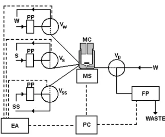
Flow-batch SAM system
The flow-batch SAM system is shown in Figure 1. A Digimed (São Paulo, Brazil) Model NK-2004 flame photometer (FP) operated according to the manufacturer’s recommendations for maximum sensitivity with air-butane was employed. A model MCP four-channel Ismatec
peristaltic pump and 1.85 mm i.d. Tygon® pumping tube
were used. The transmission lines were constructed with
0.8 mm i.d. Teflon® tubing. A 2.0 mL laboratory-made
mixing chamber (MC) was constructed in Teflon®.
Four Cole Parmer three-way solenoid valves were used: three (VW, VS and VSS) are used to direct the water, sample
and standard solution into the MC and the fourth (VD) is
used to select the stream flowing (water or MC mixture) through the photometer. A Pentium 166 MHz micro-computer equipped with a laboratory-made parallel interface card was used to control the proposed system and to perform data acquisition and treatment. The software
was developed in Labview® 5.1. An electronic actuator
(EA) increased the power of the signal sent by the microcomputer in order to control the magnetic stirrer (MS) and the valves.
Procedure
Sodium determination by flow-batch SAM. Two steps are inherent to flow-batch SAM implementation: obtaining
the SW, SSS and SS signals that are used to correct the
responses for volume changes or the flow rates of the channels (see theoretical section) and then performing the standard additions.
Before starting the flow-batch SAM procedure, the solution in each channel is pumped and recycled towards its flasks (Figure 1). Then, each valve is switched ON during a time interval of 2s and the solutions are pumped towards MC to fill the channels between the valves and MC.
Afterwards, VD is immediately switched ON and the excesses of the solutions in MC are aspirated to waste during 3s. This process, here denominated “fill channels”, takes 5s and it should be always carried out when the solution in any channel is changed.
In the first step, the standard-solution is pumped into the water channel with water in the remaining channels. After, VW, VS and VSS valves are simultaneously switched ON during a pre-selected time interval (4 seconds) and the fluids are
pumped towards MC. Keeping a suitable mixture, VD is
switched ON and the resultant solution is aspirated by the photometer, obtaining the SW signal. SS and SSS measurements are performed using the same procedure, but the standard solution is pumped in the sample channel and the later in the standard channel, while water is pumped in the remaining channels. SW, SSS and SS measurements should be carried out only sporadically or when some flow parameter is changed. To accomplish the standard additions all the valves are initially switched OFF, so that the standard solution, sample and water are continuously pumped into their channels, returning to their recipients, while water is aspirated by the photometer for baseline acquisition
(Figure 1). The VW, VS and VSS valves are then
simulta-neously switched ON during previously defined time intervals for each valve (tW, tS and tSS) and aliquots of each fluid are pumped towards MC. After MS is switched ON for homogenization, the mixture is aspirated towards the
photometer, by switching ON VD, and the
standard-additions signals, R(m), are recorded.
In the experimental design of standard additions, the total volume that is added into MC should be the same in all standard-addition levels in order to maintain the constant matrix composition or matrix effect, avoiding inaccurate results.6 Thus, t
S should always be the same
and, while tSS increases, tW decreases (and vice-versa). To correct the spectral interference of the flame background radiation caused by ethanol, the signal
acquired at the calcium channel (λmax = 621 nm) was
subtracted from the sodium one (λmax = 589.5 nm).
Sodium determination by ABNT methodology. According to ABNT methodology, the sodium emission signals of the standard-solutions used to build the ACMMS and of the alcohol fuel samples were measured after adjusting the “zero” of the flame photometer by aspirating absolute ethanol.
Theoretical
The classical expression for manually performed SAM5
is:
R(m) = KD.C0 + KD.∆C(m) (m = 0, 1, 2, 3...n) (1)
where R(m) is the response for the mth standard addition,
∆C(m); C0 is the analyte concentration in the sample; KD
is the linear response constant and n is the number of addition levels.
Since the sample volume, vS, is maintained constant
and the volumes of standard solution, vSS(m), and water,
vW(m), change with each mth standard-addition level,
equation 1 can be re-written as:
(2)
where CSS is the standard solution concentration.
In the automatic system proposed here, since v = Q t (where Q is flow rate of the channels), the valve timing, t, defines the volumes, v, added to MC. So, equation 2 can
be adapted to time rather than volume and tS, tSS, and tW
can be used instead of vS, vSS and vW.
(3)
To guarantee the same matrix composition in each standard-addition level, the total volume should be constant. As the flow rates of each channel are not strictly
the same and tSS and tW are different in each
standard-addition level, the correction volume should be imple-mented by multiplying the (tSQS + tSS(m)QSS + tW(m)QW) term in equation 3 in order to avoid systematic errors. Thus, equation 3 can be re-written as:
(tSQS + tSS(m)QSS + tW(m)QW)R(m) = KD(tSS(m)QSSCSS + tSQSCo (4)
By dividing equation 4 by QSS, equation 5 is found:
(5)
If a linear relationship exists between emission intensity and concentration of standard solution in the
measu-rements of SW, SSS and SS (see procedure session), the
following equations are obtained:
(6)
(8)
where vS, vSS, and vW are the volumes of standard solution pumped from the sample, standard solution and water channels, respectively, into MC during a same time interval,
t, vtot is the sum of the volumes pumped by each channel and
ASS is the emission signal of the standard solution.
Equations 9 and 10 can be found from equations 6, 7 and 8 and Q = v/t
(9)
(10)
Substituting equations 9 and 10 into equation 5, the following equation is found:
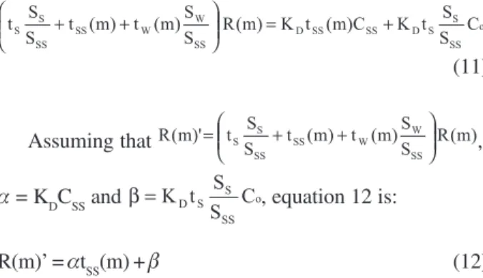
(11)
Assuming that ,
α = KDCSS and , equation 12 is:
R(m)’ = αtSS(m) + β (12)
Finally, the analyte concentration is calculated by:
(13)
where α and β are the slope and the linear coefficient of
equation 12, respectively, estimated by linear fitting employing least-squares regression.
Results and Discussion
Since the total volume of MC is equal to 2.0 mL, a flow
rate of 1.7 mL min-1 was selected for each channel in order
to achieve low sample and standard-solution consumption, as well as good sample throughput.
Due to the hydrophobic characteristics of the Teflon material used in MC, the valves and the transmission lines of the flow-batch manifold, a cleaning step was unneces-sary before each standard-addition analysis. Indeed, this was investigated by delivering the standard solution into
MC during 12 s and then emptying MC by flame photom-eter aspiration. The same procedure was then repeated with water and no blank signal (carryover) was detected in the flame photometer.
Initially, the flow-batch SAM procedure was evaluated through the determination of sodium by flame photometry in synthetic samples with different analyte contents
(0.5 - 2.5 mg L-1 Na), which were prepared in ethanol (93.6
°INPM)1,2 to promote a matrix effect similar to the alcohol
fuel samples. As seen in Table 1, the results are in good agreement with the expected values. Relative errors and standard deviations were usually smaller than 5.0 % and 0.1 mg L-1 Na (n = 4), respectively, for 0.5 – 2.5 mg L-1 Na.
The precision of the ACMMS results (ca. 0.0 mg L-1, n = 4)
was usually better than SAM because the sodium concentration is always estimated by SAM in a region of larger variance.24
The proposed SAM procedure was also applied to sodium determination by flame photometry in ten alcohol fuel samples. These results are also shown in Table 1, as well as the results using ABNT methodology. The differences observed between the SAM and ABNT results can be justified by using the t-Student test to compare the
inclinations of SAM curves, as described by Honorato et
al.4 For example, the inclinations of SAM curves of synthetic
sample 1 and alcohol fuel 6 in Table 1 are statistically different. Therefore, ACMMS yields different results if applied to estimate the analyte concentration in both samples. In this sense, the SAM approach should be favored because its outcome is not affected by matrix effects.
Table 1. Sodium contents (mg L-1) in synthetic and alcohol fuel
samples obtained by the flow-batch SAM procedure and by the ABNT methodology
Samples Flow-Batch ABNT Expected
SAM Method Value
1a 0.6 - 0.5
2a 1.0 - 1.0
3a 1.4 - 1.5
4a 2.0 - 2.0
5a 2.6 - 2.5
6 0.5 0.3
-7 1.1 1.1
-8 0.7 0.5
-9 0.5 0.4
-1 0 0.5 0.3
-1 -1 0.5 0.4
-1 2 0.2 0.0
-1 3 0.4 0.4
-1 4 0.6 0.7
-1 5 0.5 0.5
As in the flow SAM systems,17,18 which exploit the
gradient concentration of standard and sample, the proposed system requires only one standard solution to accomplish the entire standard-addition procedure. In addition, it handles about 80 – 140 samples per hour and consumes a total volume of sample and standard solution smaller than 1.5 mL for each analysis.
Conclusions
The feasibility of an automatic SAM for sodium determination by flame photometry in alcohol fuel was demonstrated. Matrix effects caused by ethanol, which increase the nebulization efficiency of the flame photometer, are satisfactorily corrected by applying a novel mathematical model derived for this flow-batch SAM.
Since alcohol fuel samples may present significant differences in matrix effects, ACMMS is not reliable because the alcoholic grade needs to be determined for each sample and the standard solutions should be prepared with a similar matrix. Thus, the ABNT methodology, although it employs matrix-matching standards, may yield inaccurate results. In this sense, alcohol fuel analyses could be more suitably accomplished by SAM. Moreover, due to the flexibility, versatility and high sample throughput of the flow-batch system, it is suggested that this new procedure be adopted as routine practice for quality control of alcohol fuel.
Acknowledgements
The authors gratefully acknowledge scholarships provided by CNPq.
References
1. Brazil: Portaria no 45 of March 16, 2001, Diário Oficial:
Brasília,DF, 19 March 2001; http://www.anp.gov.br/leg/ index.asp#anc, accessed in August 2002.
2. NBR 10422; Associação Brasileira de Normas Técnicas, São Paulo, 1988; http://www.abnt.org.br, accessed in August 2002. 3. Bhattacharjee, S.; Dasgupta, P.; Jha, Sn.; Rao, As.; Gupta, Kk.;
Pandey, Lp.; Talanta1993, 40, 675.
4. Honorato, F. A.; Honorato, R. S.; Pimentel, M. F.; Araújo, M. C. U.; Analyst2002, 127, 1520.
5. Bader, M.; J. Chem. Educ. 1980, 57, 703. 6. Kalivas, J. H.; Talanta1987, 34, 899.
7. Zagatto, E. A. G.; Jacintho, A. O.; Krug, F. J.; Reis, B. F.; Bruns, R. E.; Araújo, M. C. U.; Anal. Chim. Acta1983, 145, 169.
8. Giné, M. F.; Reis, B. F.; Zagatto, E. A. G.; Krug, F. J.; Jacintho, A. O.; Anal. Chim. Acta1983, 155, 131.
9. Tyson, J. F.; Idris, A. B.; Analyst1984, 109, 23.
10. Araújo, M. C. U.; Pasquini, C.; Bruns, R. E.; Zagatto, E. A. G.;
Anal. Chim. Acta1985, 171, 337.
11. Zhaolun, F.; Harris, J. M.; Ruzicka, J.; Hansen, E. H.; Anal. Chem. 1985, 57, 1457.
12. Giné, M. F.; Krug, F. J.; Bergamin, H.; Reis, B. F.; Zagatto, E. A. G.; Bruns, R. E.; J. Anal. At. Spectrom.1988, 3, 673. 13. Israel, Y.; Barnes, R. M.; Analyst1989, 114, 843.
14. Reis, B. F.; Giné, M. F.; Krug, F. J.; Bergamin, H.; J. Anal. At. Spectrom.1992, 7, 865.
15. Araújo, M. C. U.; Pasquini, C.; Bruns, R. E.; Quim. Nova 1993, 16, 182.
16. Assali, M.; Raimundo, I. M.; Facchin, I.; J. Autom. Methods Manage. Chem.2001, 23, 83.
17. Silva, E. C.; Araújo, M. C. U.; Honorato, R. S.; Costa Lima, J. L. F.; Zagatto, E. A. G.; Brienza, S. M. B.; Anal. Chim. Acta 1996, 319, 153.
18. Silva, E. C.; Araújo, M. C. U.; Martins, V. L.; Araújo, A. F.;
Anal. Sci.1999, 15, 1235.
19. Elsholz, O.; Frank, C.; Stachel, B.; Reincke, H.; Ebinghaus, R.; Anal. Chim. Acta2001, 438, 251.
20. Honorato, R. S.; Araújo, M. C. U.; Lima, R. A. C.; Zagatto, E. A. G.; Lapa, R. A. S.; Costa Lima, J. L. F. Anal. Chim. Acta 1999, 396, 91.
21. Honorato, R. S.; Carneiro, J. M. T.; Zagatto, E. A. G.; Anal. Chim. Acta2001, 441, 309.
22. Honorato, R. S.; Carneiro, J. M. T.; Zagatto, E. A. G.; Fresenius J. Anal. Chem.2000, 368, 496.
23. Almeida, L. F.; Martins, V. L.; Silva, E. C.; Moreira, P. N. T.; Araújo, M. C. U.; Anal. Chim. Acta, in review.
24. Neto, B. B.; Pimentel, M. F.; Araújo, M. C. U.; Quim. Nova 2002, 25, 856.
Received: October 19, 2002
Published on the web: April 9, 2003