Nanocatalysts for sustainable industrial
processes
Dissertation submitted to the University of Madeira in order to obtain the
degree of Master in Nanochemistry and Nanomaterials
By Jiawei Wang
Work developed under the supervision of
Prof. Luísa Margarida D.R.S. Martins and co-supervised by Prof. João Manuel Cunha Rodrigues
Faculdade de Ciências Exatas e de Engenharia, Centro de Química da Madeira,
Campus Universitário da Penteada, 9000-390 Funchal, Portugal
I
Declaration
I hereby declare that this thesis is the result of my own work, is original and was
written by me. I also declare that its reproduction and publication by Madeira
University will not break any third party rights and that I have not previously (in its
entirety or in part) submitted it elsewhere for obtaining any qualification or degree.
Furthermore, I certify that all the sources of information used in the thesis were properly
cited.
Lisbon, November 2015
Conference contributions
Nov. 2014 Poster Presentation in XX Encontro Luso-Galego de Química - XXLGQ S.A.C. Carabineiro, J. Wang, M. Sutradhar, L.M.D.R.S. Martins, M.F.C. Guedes da Silva, J.G. Buijnsters, A.J.L. Pombeiro, J.L. Figueiredo, Oxido-vanadium complexes heterogenised on carbon materials as catalysts for the oxidation of alcohols, Encontro Luso-Galego de Química, Porto, 2014, QI/CAT25, pág. 61. May. 2015 Poster Presentation in FÓRUM de Engenharia Química e Biológica do
ISEL
J. Wang, A.P.C. Ribeiro, L.M.D.R.S. Martins, J. Rodrigues, A.J.L. Pombeiro, Fast and efficient degradation of organic dyes with Cu nanocomposites, Fórum de Engenharia Química e Biológica'15, Instituto Superior de Engenharia de Lisboa, Portugal, 2015, pág. 23.
Oct. 2015 Poster Presentation in 2nd EuCheMS Congress on Green and
Sustainable Chemistry
A.P.C. Ribeiro, J. Wang, L.M.D.R.S. Martins, J. Rodrigues, A.J.L. Pombeiro,
Efficient Cu - MWCNT nanocomposite for the reduction of 4-Nitrophenol, 2nd
EuCheMS Congress on Green and Sustainable Chemistry, Universidade Nova de Lisboa, Portugal, 2015, M1 P11, pág. 135.
III
Acknowledgements
First of all I owe my greatest debt of gratitude to my supervisors, Professor Luísa
Margarida Martins and Professor João Rodrigues, who have given me the opportunity
to work in the field of nanoscience and helped me enrich my knowledge and broaden
my view.
I would like to express my sincere thanks to my tutor, Dr. Ana Paula Ribeiro, for
her most valuable advice and insightful comments and suggestions.
My heartfelt gratitude goes to Group I of CQE-Centro de Química Estrutural that
has provided me materials and devices for my research. All the group members,
especially my colleagues in lab, Robbe Vervecken, Marta Mendes, Elisa Spada,
Goncalo Tiago, Anbu Sellamuthu and Anup Paul, are to be thanked for making my
learning process interesting and enjoyable.
I would like to acknowledge the Portuguese Foundation for Science and
Technology (FCT) for funding through the projects UID/QUI/00100/2013 and the
NMR Portuguese Network PTNMR2014/2015.
Last but not least, I would like to thank my family for their selfless support. And
special thanks would be given to my girlfriend, Silvia Wang, for her valuable
Abstract
In Chapter 1, rhodium nanoparticles were supported on multiwalled carbon
nanotubes (MWCNTs) and bound to the magnetic core-shell system Fe3O4@TiO2. The
composite Fe3O4@TiO2-Rh-MWCNT and the intermediates were characterized by
SEM, EDS and TEM. Their catalytic activity was studied using i) the hydrogenation
transfer of nitroarenes and cyclohexene in the presence of hydrazine hydrate; ii) the
reduction of 2-nitrophenol with NaBH4; and iii) the decoloration of pigments in the
presence of hydrogen peroxide. The results were monitored by gas chromatography (i)
and UV Visible (ii and iii).
In the second chapter, the catalytic activity of six oxidovanadium(V)
aroylhydrazone complexes, viz. [VOL1(OEt)][VOL1(OEt)(EtOH)] (1), [VOL2(OEt)]
(2), [Et3NH][VO2L1] (3), [VO2(H2L2)]·2EtOH (4), [VOL1(µ-O)VOL1] (5) and
[VOL2(µ-O)VOL2] (6) (H2L1 = 3,5-di-tert
-butyl-2-hydroxybenzylidene)-2-hydroxybenzohydrazide and H2L2 = 3,5-di-tert
-butyl-2-hydroxybenzylidene)-2-aminobenzohydrazide), anchored on nanodiamonds with different treatments, was
studied towards the microwave-assisted partial oxidation of 1-phenylethanol to
acetophenone in the presence of tert-butyl hydroperoxide (TBHP) as oxidant. A high
selectivity for acetophenone was achieved for the optimized conditions. The possibility
of recycling and reuse the heterogeneous catalysts was also investigated.
In chapter 3, the catalytic activity of gold nanoparticles supported at different metal
oxides, such as Fe2O3, Al2O3 ZnO or TiO2, was studied for the above reaction. The
effect of the support, quantity of the catalyst and temperature was investigated. The
recyclability of the gold catalysts was also studied.
In the last chapter, a new copper nanocomposite with functionalized mutiwalled
carbon nanotubes (Cu-MWCNT) was synthesized using a microwave assisted polyol
method. The characterization was performed using XRD and SEM. The catalytic
activity of Cu-MWCNT was studied through the degradation of pigments, such as
V
Keywords: nanoparticle, magnetic catalyst, gold, vanadium, rhodium, copper,
Resumo
No capítulo 1, nanopartículas de ródio foram suportadas em nanotubos de carbono
de paredes múltiplas (MWCNT) e ligadas ao sistema magnético constitudo por
magnetite envolvida em dióxido de titânio (Fe3O4@TiO2). O compósito formado por
Fe3O4@TiO2-Rh-MWCNT e respectivos intermediários foram caracterizados por SEM,
EDS e TEM. A actividade catalítica foi estudada nos seguintes sistemas: i)
hidrogenação por transferência de nitroarenos e ciclohexeno na presença de hidrazina
como agente redutor; ii) redução de 2-nitrofenol com NaBH4 como agente redutor; e
iii) descoloração de pigmentos utilizando peróxido de hidrogénio como agente oxidante.
Todos os resultados experimentais foram monitorizados por cromatografia gasosa no
caso de i) e por espectroscopia de UV-Vis no caso de ii) e iii).
No capítulo 2 é reportada a atividade catalítica de seis compostos de
aroilhidrazona-oxi-vanádio(V), [VOL1(OEt)][VOL1(OEt)(EtOH)] (1), [VOL2(OEt)]
(2), [Et3NH][VO2L1] (3), [VO2(H2L2)]·2EtOH (4), [VOL1(µ-O)VOL1] (5) and
[VOL2(µ-O)VOL2] (6) (H2L1 =
3,5-di-terc-butil-2-hidroxibenzilideno)-2-hidroxibenzohidrazida e H2L2 =
3,5-di-terc-butil-2-hidroxibenzilideno)-2-aminobenzohidrazida), suportados em nanodiamantes, produzidos recorrendo a
diferentes metodologias. Estes compostos foram estudados como catalisadores na
oxidação parcial, sob radiação de micro-ondas, de 1-feniletanol a acetofenona
utilizando hidroperóxido de terc-butilo (TBHP) como oxidante. Nas condições
optimizadas observou-se uma elevada seletividade em relação à formação de
acetofenona. Foram efetuados estudos de reciclagem e reutilização dos catalisadores
heterogéneos.
No terceiro capítulo, é descrita a atividade catalítica de nanopartículas de ouro
suportadas em vários óxidos metálicos (Fe2O3, Al2O3 ZnO ou TiO2). Foi estudado o
efeito de vários parâmetros reacionais tais como suporte utilizado, quantidade de
catalisador e temperatura. Foram também efetuados estudos de reciclagem dos
catalisadores de ouro.
VII
por cobre e MWCNT, na degradação de pigmentos, nomeadamente amarant, azul
brilhante, indigo, tartazine e azul de metileno. A caracterização do nanocompósito foi
feita por SEM, XRD e espectroscopia de IV.
Palavras chave: nanopartículas, catalisador magnético, ouro, vanádio, ródio, cobre,
Index
Declaration ... I
Conference contributions ... II
Acknowledgements ... III
Abstract ... IV
Resumo ... VI
Index ... VIII
List of Figures ... XI
List of Schemes ... XIV
List of Tables ... XV
List of acronyms, abbreviations and symbols ... XVII
Chapter 1 Synthesis and catalytic study of rhodium based magnetic nanoparticles ... 1
1. INTRODUCTION ... 1
1.1 Catalytic importance in hydrogenation ... 2
1.2 Magnetic Supports ... 4
2. EXPERIMENTAL ... 7
2.1 Materials ... 7
2.2 Instruments ... 7
2.2.1 Characterization ... 7
2.2.2 Catalysis ... 7
2.3 Synthesis... 8
2.3.1 Synthesis of Fe3O4@TiO2 core-shell system ... 8
2.3.2 Functionalization of MWCNT ... 10
2.3.3 Synthesis of size-tunable rhodium nanoparticles supported on carbon nanotubes ... 10
2.3.4 Synthesis of Rh supported on Fe3O4@TiO2 ... 11
2.3.5 Synthesis of MWCNT-Rh supported on Fe3O4@TiO2 ... 11
2.4 Catalytic studies ... 12
2.4.1 MW-assisted catalytic hydrogenation transfer of cyclohexene and nitroarenes ... 12
2.4.2 Catalytic reduction of 2-nitrophenol with NaBH4. ... 14
2.4.3 Catalytic decoloration of organic pigments ... 15
3. RESULTS AND DISCUSSION ... 17
3.1 Synthesis of metallic nanoparticles ... 17
3.2 Hydrogenation transfer of nitroarenes and cyclohexene ... 29
3.3 Reduction of 2-Nitrophenol ... 33
3.4 Pigment decoloration ... 38
3.4.1 Decoloration of amaranth ... 39
3.4.2 Decoloration of tartrazine ... 42
IX
4. CONCLUSION ... 47
REFERENCES ... 48
Chapter 2 MW-assisted oxidation of 1-phenylethanol catalyzed by oxidovanadium(V) complexes supported on nanodiamonds ... 54
1. INTRODUCTION ... 54
2. EXPERIMENTAL ... 58
2.1 Materials and instruments ... 58
2.2 Experimental procedure ... 59
2.2.1 Products extraction and analysis ... 60
2.2.2 Recycling experiments ... 61
3. RESULTS AND DISCUSSION ... 61
4. CONCLUSION ... 66
REFERENCES ... 67
Chapter 3 MW-assisted oxidation of 1-phenylethanol catalysed by gold nanoparticles supported on different materials ... 72
1. INTRODUCTION ... 72
1.1 Main factors that affect the catalytic activity of gold ... 74
1.1.1 Size of gold nanoparticles ... 74
1.1.2 The effect of carriers ... 74
1.1.3 The effect of load size of gold ... 75
2. EXPERIMENTAL ... 75
2.1 Materials and instruments ... 75
2.2 Experimental procedure ... 76
2.2.1 Gold loading ... 76
2.2.2 MW-assisted 1-phenylethanol oxidation ... 77
2.2.3 Recycling Experiment ... 78
2.3 GC analysis ... 79
3. RESULTS AND DISCUSSION ... 79
3.1 Characterization ... 79
3.1.1 BET surface area ... 79
3.1.2 HRTEM images ... 80
3.1.3 EDS analysis ... 81
3.2 Oxidation of 1-phenylethanol ... 81
3.2.1 Influence of the supports ... 83
3.2.2 Influence of temperature ... 84
3.2.3 Influence of quantity of catalyst ... 85
3.3 Recycling Experiment ... 85
4. CONCLUSION ... 86
REFERENCES ... 87
Chapter 4 MWCNT supported copper nanoparticles used for degradation of pigments90 1. INTRODUCTION ... 90
2.1 Materials and Equipments... 91
2.2 Synthesis of Cu-MWCNT nanocomposite ... 92
2.3 Degradation of Dye ... 93
3. RESULTS AND DISCUSSION ... 93
3.1 Synthesis of Cu-MWCNT nanocomposite ... 93
3.2 Degradation of Dye ... 95
4. CONCLUSION ... 100
XI
List of Figures
Figure 1- 1Structure of Wilkinson’s catalyst. ... 2
Figure 1- 2 A) Synthesis of MWCNT supported rhodium nanoparticles in ultrasonic bath. B) TEM images of MWCNT supported rhodium nanoparticles. C) Hydrogenation of arenes catalyzed by MWCNT supported rhodium nanoparticles. ... 3
Figure 1- 3 One pot preparation of TiO2 supported Rh(0) nanoparticles. ... 4
Figure 1- 4 Synthesis of Fe3O4@SiO2@TiO2 composite spheres. ... 6
Figure 1- 5 Synthesis of Fe3O4@TiO2. ... 9
Figure 1- 6 Synthesis of Rh- Fe3O4@TiO2. ... 11
Figure 1- 7 Fe3O4 nanoparticles produced at (A) 50 °C and (B) 80 °C. ... 17
Figure 1- 8 TEM images of Fe3O4 nanoparticles. ... 18
Figure 1- 9 SEM images of Fe3O4 nanoparticles. ... 18
Figure 1- 10 EDS spectrum of Fe3O4 nanoparticles. ... 19
Figure 1- 11 TEM images of Fe3O4@TiO2 nanoparticles. ... 20
Figure 1- 12 SEM image of Fe3O4@TiO2 nanoparticles. ... 20
Figure 1- 13 EDS spectrum of Fe3O4@TiO2 nanoparticles. ... 21
Figure 1- 14 XPS spectra of Baytubes 150HP. ... 21
Figure 1- 15 XRD analysis of Baytubes 150HP. ... 22
Figure 1- 16 TEM analysis of Baytubes 150HP ... 22
Figure 1- 17 SEM image of (A) Baytubes 150HP and (B) functionalized MWCNT. ... 23
Figure 1- 18 Raman spectra of (a) pure MWCNTs and of (b) factionalized MWCNTs. ... 24
Figure 1- 19 TEM images of MWCNT-Rh nanoparticles. The dark points on the nanotubes surface are rhodium. ... 25
Figure 1- 20 SEM image of MWCNT-Rh nanoparticles. ... 25
Figure 1- 21 EDS spectrum of MWCNT-Rh nanoparticles. ... 26
Figure 1- 22 TEM images of Fe3O4@TiO2-Rh nanoparticles. ... 27
Figure 1- 23 SEM images of Fe3O4@TiO2-Rh nanoparticles. ... 27
Figure 1- 24 EDS spectrum of Fe3O4@TiO2-Rh nanoparticles. ... 27
Figure 1- 25 TEM images of Fe3O4@TiO2-Rh-MWCNT nanoparticles. ... 28
Figure 1- 26 SEM image of Fe3O4@TiO2-Rh-MWCNT nanoparticles. ... 28
Figure 1- 27 EDS spectrum of Fe3O4@TiO2-Rh-MWCNT nanoparticles. ... 29
Figure 1- 28 Synthesized nanoparticles, A) Fe3O4, B) MWCNT-Rh, C) Fe3O4@TiO2, D) Fe3O4@TiO2-Rh, E) Fe3O4@TiO2-Rh-MWCNT, F) Fe3O4@TiO2-Rh-MWCNT. ... 29
Figure 1- 29 Hydrogenation transfer of cyclohexene and nitroarenes catalyzed by different nanoparticles. ... 31
Figure 1- 30 Separation of catalysts with magnet. ... 32
Figure 1- 31 Results of catalytic recycling for the MW-assisted hydrogenation (10 min) of nitrobenzene with hydrazine at 80 °C catalyzed by Fe3O4@TiO2-Rh-MWCNT. ... 33
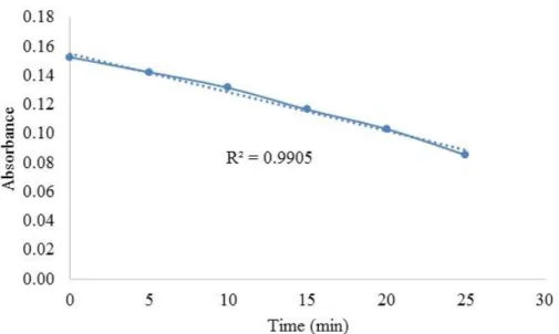
Figure 1- 32 UV-Vis spectra of the reduction of 2-nitophenol catalyzed by Fe3O4@TiO2 -Rh-MWCNT. ... 34
Figure 1- 33 Plot of the absorbance at the peak of 351 nm vs. time. ... 35
Figure 1- 35 During the reduction, the light yellow color of 2-nitrophenol changed to dark
orange. After 30 min of reaction an orange flocculation appeared in the solution. ... 36
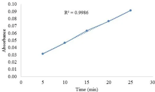
Figure 1- 36 UV-Vis spectra of the reduction of 2-nitrophenol catalyzed by MWCNT-Rh. .. 36 Figure 1- 37 The plot of the absorbance at the peak of 351 nm vs. time. ... 37 Figure 1- 38 The plot of ln (At/A0) vs. time of the reduction of 2-nitrophenol, kapp = 0.0659
min-1. ... 37
Figure 1- 39 The color changing of amaranth pigment after 5 min of reaction using
Fe3O4@TiO2-Rh-MWCNT as catalyst in the cells at different pH value. ... 40
Figure 1- 40 UV spectrum of the amaranth pigment catalyzed by Fe3O4@TiO2-Rh-MWCNT
with the presence of H2O2 as oxidant at pH 2, 7 and 12. And the plot of absorbance at
maximum absorption wavelength of amaranth pigment to time at pH 2, 7 and 12. ... 40
Figure 1- 41 Decoloration rates of amaranth pigment using as catalyst at pH 2, 7 and 12. ... 41 Figure 1- 42 Color changing of tartrazine dye after 5 min of reaction using Fe3O4@TiO2
-Rh-MWCNT as catalyst in the cells at different pH value. ... 42
Figure 1- 43 UV-Vis spectrum of tartrazine pigment catalyzed by Fe3O4@TiO2-Rh-MWCNT
in presence of H2O2 as oxidant at pH 2, 7 and 12. And the plot of absorbance at maximum
absorption wavelength of tartrazine pigment to time at pH 2, 7 and 12. ... 43
Figure 1- 44 Decoloration rates of tartrazine pigment using Fe3O4@TiO2-Rh-MWCNT as
catalyst at pH 2, 7 and 12. ... 43
Figure 1- 45 The color changing of brilliant blue after 5 min of reaction using Fe3O4@TiO2
-Rh-MWCNT as catalyst in the cells at different pH value. ... 45
Figure 1- 46 The UV-Vis spectrum of brilliant blue pigment catalyzed by Fe3O4@TiO2
-Rh-MWCNT in presence of H2O2 as oxidant at pH 2, 7 and 12. And the plot of absorbance at
maximum absorption wavelength of brilliant blue pigment to time at pH 2, 7 and 12. .. 45
Figure 1- 47 Decoloration rates of brilliant blue pigment using Fe3O4@TiO2-Rh-MWCNT as
catalyst at pH 2, 7 and 12. ... 46
Figure 2- 1 Acetophenone yields produced by MW-assisted and solvent-free oxidation of
1-phenylethanol catalyzed by vanadium complexes 1, 2, 5 and 6 in homogeneous conditions
and immobilized in twelve different carbon materials: CX, AC, CNT and ND with different treatments. The data concerning CX, AC and CNT was obtained from references [16] and [33]. Some of the samples are not shown in this figure, because the vanadium loading is very low. ... 63
Figure 2- 2 Effect of the temperature on the acetophenone yield produced by oxidation of
1-phenylethanol in the presence of 6@NDox after 0.5 h of MW (10 W power) irradiation.
... 64
Figure 2- 3 Yield of acetophenone produced by MW-assisted oxidation of 1-phenylethanol
(0.5 h) catalyzed by compounds 3 or 4 in homogeneous conditions or supported on
nanodiamond materials with different treatments. ... 65
Figure 2- 4 Effect of the catalyst recycling on the yield of acetophenone for the MW-assisted
oxidation (0.5 h) of 1-phenylethanol with TBHP, at 125 ºC catalysed by 4@ND. ... 66
XIII
spots). ... 80
Figure 3- 2 HRTEM image of A Au@CNT, B Au@AC (gold nanoparticles seen as darker spots). ... 80
Figure 3- 3 The yield of acetophenone catalyzed by the supports and supported gold nanoparticles. Condition: 100 °C, 60 min, 600 rpm, microwave reactor, 10W. ... 83
Figure 3- 4 Effect of different temperature in catalytic oxidation of 1-phenylethanol. ... 84
Figure 3- 5 The plot of yields of cycling test reactions to cycles. ... 86
Figure 4- 1 XRD spectra of Cu-MWCNT produced. ... 94
Figure 4- 2 SEM images of Cu-MWCNT nanocomposite powder. a) x30000; b) x15000. ... 94
Figure 4- 3 UV spectra of Methylene blue. ... 95
List of Schemes
Scheme 1- 1 Synthesis of Fe3O4 magnetic nanoparticles. ... 9
Scheme 1- 2 Representation of the synthesis of Fe3O4@TiO2 core-shell nanoparticles. ... 9
Scheme 1- 3 Proposed representation of the synthesis of MWCNT-Rh. ... 10
Scheme 1- 4 Representation of the synthesis of Fe3O4@TiO2-Rh... 11
Scheme 1- 5 Proposed representation of the synthesis of Fe3O4@TiO2-Rh-MWCNT. ... 12
Scheme 1- 6 Hydrogenation transfer of nitrobenzene catalyzed by different nanoparticles. . 13
Scheme 1- 7 Reduction of 2-nitrophenol catalyzed by MWCNT-Rh or Fe3O4@TiO2 -Rh-MWCNT. ... 15
Scheme 2- 1 Aerobic oxidation of alcohols catalyzed by vanadium catalysts. ... 54
Scheme 2- 2 Synthesis of oxidovanadium(V) complexes 1-6. ... 56
Scheme 2- 3 MW-assisted oxidation of 1-phenylethanol to acetophenone catalyzed by oxidovanadium(V) complexes in the presence of TBHP as oxidant. ... 56
XV
List of Tables
Table 1- 1 MW-assisted catalytic hydrogenation transfer of different substrates. ... 13
Table 1- 2 Recycling experiments of the MW-assisted hydrogenation (10 min) of nitrobenzene with hydrazine at 80 °C catalyzed by Fe3O4@TiO2-Rh-MWCNT. ... 14
Table 1- 3 Structure of the pigments used in the catalytic study. ... 16
Table 1- 4 The results of the hydrogenation transfer of cyclohexene and nitroarenes catalyzed by different catalysts. ... 30
Table 1- 5 Catalytic recycling for the MW-assisted hydrogenation (10 min) of nitrobenzene with hydrazine at 80 °C catalyzed by Fe3O4@TiO2-Rh-MWCNT. ... 32
Table 1- 6 Maximum absorbance wavelength of the pigments at studied pH value. ... 38
Table 1- 7 The color of the pigments before and after the decoloration catalyzed by Fe3O4@TiO2-Rh-MWCNT complex in different pH value. ... 39
Table 1- 8 Rates and conversion of amaranth decoloration catalyzed by Fe3O4@TiO2 -Rh-MWCNT. ... 41
Table 1- 9 Rate and conversion of tartrazine decoloration catalyzed by Fe3O4@TiO2 -Rh-MWCNT. ... 44
Table 1- 10 Rate and conversion of brilliant blue decoloration catalyzed by Fe3O4@TiO2 -Rh-MWCNT. ... 46
Table 2- 1 V loading (% p/p) on the nanodiamonds. ... 58
Table 2- 2 Description and characterisation of (powder) carbon samples. ... 59
Table 2- 3 MW-assisted oxidation of 1-phenylethanol with TBHP catalyzed by vanadium complexes 1-6 supported at nanodiamonds. ... 60
Table 2- 4 Recycling experiments of 4@ND in consecutive oxidations of 1-phenylethanol. 61 Table 2- 5 Selected data for the MW-assisted oxidation of 1-phenylethanol catalyzed by vanadium complexes 1-6 immobilized on different types of nanodiamonds (ND, NDox and NDoxNa). ... 62
Table 2- 6 MW-assisted solvent-free oxidation of 1-phenylethanol in the presence of the nanodiamonds ND, ND-ox and ND-ox-Na. ... 63
Table 2- 7 Effect of the catalyst recycling on the yield of acetophenone for the MW-assisted oxidation (0.5 h) of 1-phenylethanol with TBHP, at 125 ºC catalyzed by 4@ND. ... 65
Table 3- 1 The oxidation of 1-phenylethanol catalyzed by the support materials. ... 77
Table 3- 2 The oxidation of 1-phenylethanol catalyzed by supported gold nanoparticles. ... 78
Table 3- 3 The oxidation of 1-phenylethanol catalyzed by recycling gold nanoparticles... 78
Table 3- 4 BET surface area of supports... 79
Table 3- 5 Characterization of the supported gold nanoparticles by EDS. ... 81
Table 3- 6 MW-assisted catalytic oxidation of 1-phenylethanol catalyzed by supports and gold nanoparticles. ... 82
Table 3- 7 The oxidation of 1-phenylehtanol catalyzed by supported gold nanoparticles and only the support. ... 83
reaction temperature. ... 84
Table 3- 9 The results of the recycling tests catalyzed by TiO2 supported gold nanoparticles in different recycling methods. ... 85
Table 4- 1 Structure of the pigments used in catalytic study. ... 92
Table 4- 2 Maximum absorbance wavelength of the pigments at studied pH value. ... 95
XVII
List of acronyms, abbreviations and symbols
CNT Carbon Nanotube
MWCNT Multiwalled Carbon Nanotube
TEM Transmission Electron Microscopy
SEM Scanning Electron Microscope
EDS Energy-dispersive X-ray Spectroscopy
MNP Metal Nanoparticle
TBHP tert-Butyl Hydroperoxide
XRD X-ray Diffraction
IR Infrared Spectrometry
GC Gas Chromatography
MW Microwave
GC-MS Gas Chromatography–Mass Spectrometry
TLC Thin Layer Chromatography
UV-Vis Ultraviolet–Visible Spectroscopy
Chapter 1
Synthesis and catalytic study of rhodium based
magnetic nanoparticles
1.
Introduction
In 1803, Wollaston[1], a British chemist and physicist, isolated two new elements,
rhodium and palladium, from coarse platinum. Rhodium is one of the rarest and the
most costly metals. This noble metal has found many catalytic applications, particularly
in hydrogenation reactions owing to its specific catalytic properties[1]. This interest for
rhodium catalysts concerns also the modern “nanocatalysis” area, situated at the frontier
between heterogeneous and homogeneous ones, nanoparticles soluble in a liquid phase
being considered as “pseudo homogeneous” systems.
Metal nanoparticles, generally defined as particles between 1 and 10 nm, have
received during the last fifteen years an increasing attention from the researchers all
over the world. This is mainly due to their particular matter state (very small size and
quantum size effects; unusual electronic state) that provides novel physical and
chemical properties and further, multiple potential applications in various areas[2, 3]. In
the context of the development of nanosciences, nanocatalysis has emerged as a
promising domain to answer the demanding conditions for catalyst improvement[4-9].
Thus, metallic nanospecies are expected to display the benefits of both homogenous
and heterogeneous catalysts, namely high efficiency and selectivity, as well as
recyclability.
Nanomaterial-based catalysts are usually heterogeneous catalysts broken up into
metal nanoparticles in order to speed up the catalytic process. Metal nanoparticles have
a higher surface area than bulk particles so there is increased catalytic activity because
more catalytic interactions with the substrate can occur at the same time. Nanoparticle
catalysts can also be easily separated and recycled with more retention of catalytic
activity than their bulk counterparts[10]. These composites can play two different roles
2
catalytic processes[11]. They are typically used under mild conditions to prevent
decomposition of the nanoparticles[12].
1.1
Catalytic importance in hydrogenation
Hydrogenation reactions are one of the most important methods in organic
synthesis. They have extensive uses in modern industry, especially in pharmaceutical
synthesis. Using a proper catalyst can not only shorten the reaction time, increase the
yield, but also reduce the costs. In this field, one of the most famous rhodium catalysts
is Wilkinson’s catalyst[13] (Figure 1- 1). In the field of nanocatalysis, hydrogenation
reactions are the most often cited reactions for which rhodium nanoparticles are
developed[13].
Figure 1- 1 Structure of Wilkinson’s catalyst.
In order to make a rhodium catalyst more active, stable and separable from the
reaction mixture, its anchorage on a solid support is usually one of the most efficient
strategies. Carbon nanotubes (CNTs) due to their large length-to-diameter ratio,
physical and chemical stabilities, nontoxic nature, low cost, thermal conductivity and
electronic properties are widely applied as additive or support to various materials [14].
Some recent papers reported that the CNT supported catalysts had a significant high
catalytic activity and selectivity compared with the non-supported ones [15].
Pan and coworkers[16] described a simple and capping agent free method to
synthesize a CNT-supported rhodium catalyst for the hydrogenation of arenes at room
temperature. The synthetic method, TEM image of CNT-supported rhodium
nanoparticles and the hydrogenation of arenes are shown in Figure 1- 2. The rhodium
nanocatalyst has advantages of high activity, selectivity and recyclability. They[16] also
nanotubes (MWCNTs) supported rhodium nanoparticles. The size of the material was
controlled by adding boron containing reducing agents to reduce Rh3+ ions. The average
size of the particles is in nanoscale (2-8 nm) [17]. The size-tunable rhodium nanoparticles
supported at MWCNTs have a high catalytic activity and stereoselectivity for the
hydrogenation of xylene. Therefore the MWCNT supported catalysts have broad
prospects for industrial applications[14].
Figure 1- 2 A) Synthesis of MWCNT supported rhodium nanoparticles in ultrasonic
bath. B) TEM images of MWCNT supported rhodium nanoparticles. C) Hydrogenation
of arenes catalyzed by MWCNT supported rhodium nanoparticles [16].
Because of the unique properties of CNTs, they not only serve as supports for the
nanoparticles, but also provide straight pathways, which are conductive, for the
electrons to transfer through. Therefore MWCNTs with multiple layers have more
potential than single wall CNTs. A recent paper reported by Casella and coworkers [18]
described a method to synthesize the MWCNT-Rh catalyst used for electrochemical
reduction of nitrate and nitrite species. They[18] acid-treated the MWCNTs to contain
carboxyl acid groups on the surface. Then the acid-treated MWCNTs were treated with
polished glassy carbon substrate and cycled in RhCl3 containing H2SO4 to form glassy
carbon/MWCNT-Rh catalyst. Finally the electrodes based on rhodium particles were
demonstrated to have a high catalytic activity on electrochemical reduction of nitrate
and nitrite species.
Another common solid support for rhodium is TiO2 nanoparticles. TiO2 is used as a
4
surface. Moreover, TiO2 can release energy, free ·OH and ·O2- to promote the process
of reactions [19]. Hubert and coworkers [20] reported a simple one-pot method to prepare
rhodium(0) colloid catalyst on TiO2 in the presence of
N,N-dimethyl-N-cetyl-N-(2-hydroxyethyl) ammonium chloride (HEA16Cl) and NaBH4 at room temperature
(Figure 1- 3). The colloidal catalyst is highly active and recyclable for the
hydrogenation of aromatics with TOF (turnover frequency) values up to 33000 h-1. The
same authors compared the prepared Rh@TiO2 with Rh@SiO2, concluding that a
higher catalytic selectivity and activity were obatained with Rh@TiO2 catalysts.
Figure 1- 3 One pot preparation of TiO2 supported Rh(0) nanoparticles[20].
1.2
Magnetic Supports
The development of new strategies for recovery and recycling of catalysts to
enhance their lifetime and minimize the consumption of auxiliary substances and
devices used in achieving separations can result in significant economic and
environmental benefits[21]. Ongoing research activities in this area include the use of
metal nanoparticles (MNPs) [21-23]. It is widely accepted that MNPs are very active
catalysts because of their large surface area and great ratio of atoms remaining at the
surface, and so available to the chemical transformation of substrates. However, MNPs
must be stabilized by protective agents to prevent agglomeration to the
thermodynamically favoured bulk metal. In addition, the separation of the catalysts
from the reaction products is also very important[24]. Attempts to improve separation
include the use of biphasic aqueous/organic systems [25-27], ionic-liquid biphasic
practical point of view, catalysts that are not soluble in the same phase as organic
reactants have the inherent advantage of easy separation. However, supported catalysts
may also exhibit severe problems (e.g. TiO2 supported Cu causes reduction in specific
surface area) with respect to catalyst recovery in liquid-phase batch reactions. In this
scenario, immobilization of catalysts on magnetically separable solid supports appears
as an attractive way to give better handling properties to homogeneous[35-40] and MNP
catalysts[41, 42]. Solid supports containing magnetic nanoparticles can be easily separated
from the product of interest due to the magnetic interaction between the magnetic
nanoparticles and an external applied magnetic field. Furthermore, magnetic separation
constitutes an alternative approach to traditional time- and solvent-consuming steps
during the purification process since it is fast, it can be easily scaled-up, and it does not
make use of other chemical reagents and solvents that present considerable
environmental hazards[41].
Magnetic nanoparticles, including Co, Fe, Ni, Fe3O4 and their alloys, have been
developed to have various industrial applications. Among all the magnetic
nanoparticles, Fe3O4 has been applied most widely. Considering the synthesis of Fe3O4
nanoparticles, coprecipitation is the most facile and convenient way to synthesize iron
oxide by aqueous solution. Saira-Riaz and coworkers[43] reported a simple
coprecipitation method to synthesize Fe3O4 from dissolving FeCl3.6H2O and
FeCl2.4H2O in deionized water with the molar ratio of 2:1. The solution was stirred and
protected by argon atmosphere at 80°C. Then, an NaOH solution was added dropwise
to adjust the pH value. Finally the Fe3O4 nanoparticles were obtained with size between 25 and 100 nm. With the increase in pH values, an increase in nanoparticles’ diameter was observed.
In order to maintain a stable material for a longer time, to improve the stability of
magnetic nanoparticles during the synthesis is important. Since the magnetic
nanoparticles are sensitive to air, an efficient strategy to improve the stability[44] is
applying a coating layer to protect the magnetic nanoparticles from corrosion. As
reported by Ma and coworkers[45], magnetic core-shell nanoparticles of
6
superparamagnetic Fe3O4 spheres using a modified one-step solvothermal method.
Then the magnetic Fe3O4 nanoparticles were coated by SiO2 through asol–gel process
with minor modifications[46]. Finally TiO2 nanoparticles were coated on the surface of
Fe3O4@SiO2 in an ultrasonic bath (Figure 1- 4).
Figure 1- 4 Synthesis of Fe3O4@SiO2@TiO2 composite spheres[45].
Based on the MWCNT and TiO2 support, in our study, we combined both of the
above methods to achieve a rhodium composite that has the advantages of both CNT
and TiO2 supports. In addition, we treated the TiO2 to form a core-shell system, which
was Fe3O4 coated by TiO2. To study the catalytic properties of the synthesized
nanoparticles, we used our nanoparticles as catalysts for hydrogenation reactions
(Table 1- 1) and oxidation of pigments (Table 1- 2). Thanks to the supermagnetic
property of Fe3O4 nanoparticles, the rhodium based nanoparticles can inherit the
magnetic property. As a result, the catalysts are easier to separate and be reused for
several cycles. To the best of our knowledge, there is no report in the literature using
this method to support rhodium and analysed using hydrogenation of nitroarenes and
cyclohexene. We also report the possibility of the decoloration of several pigments
2.
Experimental
2.1
Materials
Ethyl acetate (99.9%), acetone (C3H6O; purity of 99.8%), diethyl ether (99.97%)
acetonitrile (ACN, 99.99%) were from Fisher Scientific. Nitric acid (HNO3, purity of
65%) and hydrochloric acid (HCl; purity of 37%) were purchased from Panreac.
2-nitrophenol, 2-aminophenol, 4-2-nitrophenol, 4-aminophenol, nitrobenzene, aniline,
cyclohexene (C6H12; purity >99%), hydrogen peroxide (H2O2; purity of 30% v/v),
cyclohexane, (NH4)2Fe(SO4)2•6H2O, FeCl3•6H2O, solid TiO2 nanopowder (< 25 nm),
titanium(IV) isopropoxide (98%) Ti{OCH(CH3)2}4 solution, absolute ethanol (EtOH;
purity of 99.9%), isopropanol, NaBH4, hydrazine hydrate, RhCl3, NaOH, MgSO4 were
all from Sigma-Aldrich. MWCNTs were supplied by Bayer Materials. The pigments of
methylene blue, brilliant blue, tartrazine and amaranth were from Merck. All chemicals
used were analytical grade without further purification. TLC plates (Silica Gel 60) were
from WVR.
2.2
Instruments
2.2.1 Characterization
The synthesized nanoparticles were characterized by scanning electron microscope
(SEM), transmission electron microscopy (TEM) and energy-dispersive X-ray
spectroscopy (EDS) techniques. SEM images of the synthesized nanoparticles were
performed on a scanning electron microscope JEOL 7001F with Oxford light elements
EDS detector and EBSD detector. TEM measurements were carried out on a
Transmission Electron Microscope Hitachi 8100 with ThermoNoran light elements
EDS detector and digital image acquisition. X-Ray Photoelectron Spectrometer (XPS)
measurements were performed with ESCALAB 250 XPS spectrometer,
2.2.2 Catalysis
8
agitation function, to keep the reaction at a constant temperature, making convection
possible and thus preventing diffusion to become a restrictive factor. Microwave reactor
(MW) Anton Paar Monowave 300 was used for the MW-assisted hydrogenation of
cyclohexene and nitroarenes. The gas chromatograph MFC 8000 from Fisons
instruments, was utilized for the analysis of the product containing water phase. It is a
GC with flame ionization detector and capillary column (DB-WAX, column length: 30
m; internal diameter: 0.32 mm) and the Jasco-Borwin v.1.50 software. 0.045 µL of the
sample got injected and subsequently analyzed. A temperature program with an initial
temperature of 100 °C (1 min) and a ramp of 10 °C/min with a final temperature of
180 °C (1 min).
GC-MS (PerkinElmer Clarus 600C Mass spectrometer, Clarus 600 Gas
Chromatography) was used to identify compounds. UV-visible spectroscopic
measurements were carried out on a PerkinElmer Lambda 750 UV-Visible
spectrophotometer.
2.3
Synthesis
2.3.1 Synthesis of Fe3O4@TiO2 core-shell system
The preparation of Fe3O4@TiO2 core-shell particles was separated into two parts.
The first step was the synthesis of magnetic Fe3O4 nanoparticles using the
co-precipitation method. 1 mmol of(NH4)2Fe(SO4)2•6H2O and 2 mmol of FeCl3•6H2O
were added to 80 mL of H2O in a round bottom flask. The mixture was stirred at 600
RPM in a 50 °C oil bath. Then a 1 mol/L NaOH solution was dropped into the mixed
solution until the pH value reached 10. After that, instead of brown solid particles, black
precipitates appeared rapidly in the flask, which was Fe3O4 nanoparticles (Scheme 1-
1). The reaction was stopped and cooled down to room temperature. The Fe3O4
precipitate was filtered and washed with distilled water and ethanol several times. Then
the Fe3O4 nanoparticles were dried in oven and collected for next synthesis. TEM and
(NH4)2Fe(SO4)2•6H2O + FeCl3•6H2O 𝑁𝑎𝑂𝐻, 50°𝐶, 600𝑅𝑃𝑀→ Fe3O4
Scheme 1- 1 Synthesis of Fe3O4 magnetic nanoparticles.
The second step is the coating of Fe3O4 by TiO2 [47]. The core-shell system of Fe3O4
was prepared by 0.43 mmol (100 mg) of Fe3O4 nanoparticles and 3.38 mmol (1 mL) of
titanium(IV) isopropoxide (98%) Ti{OCH(CH3)2}4 solution in 250 mL of dry ethanol
stirred under 1500 RPM. Then 7 mL of dry ethanol and 1 mL of distilled H2O were
added into the mixture. The mixed solution was heated at reflux (75 °C) under magnetic
stirring for 3 hours (Figure 1- 5). At the end, the samples were cooled down till room
temperature and separated magnetically. The particles were washed with ethanol and
distilled water, dried in oven at 80 °C and stored for future applications. TEM and SEM
images, and EDS are shown in Figure 1- 11, 1- 12 and 1- 13 respectively.
Figure 1- 5 Synthesis of Fe3O4@TiO2.
Fe3O4
Ti{OCH(CH3)2}4 in EtOH 1500 RPM
Ti{OCH(
CH3)2}3
Ti{O CH(CH
3)2}
3
{OC H(CH
3)2}
3Ti
{OCH(C H3)2}3
Ti
Fe3O4
H2O 70 °C reflux, 3 hours
1500 RPM
Fe3O4
TiO2
10
2.3.2 Functionalization of MWCNT
According to literature, the functionalization of these nanomaterials can be
performed with various methods, such as ball milling, plasma treatment and acid
treatment[48]. In the present study, a non-destructive acid treatment was carried out. For
this purpose, 1 g of MWCNT was added to 200 mL of concentrated HCl (37%) in a
round bottom flask (500 mL). After that, the mixture was stirred for 2 hours.
Subsequently, a vacuum filtration was developed with several washing steps (deionized
water) until a pH= 7 was obtained. Finally, the resulting material was dried in a
convection oven at 40ºC overnight.
2.3.3 Synthesis of size-tunable rhodium nanoparticles supported on carbon nanotubes
For this procedure, 80 mg of carboxyl group functionalized multiwalled carbon
nanotubes (MWCNTs) were charged in a 250 mL flask containing 80 mL of ethanol.
The solution was sonicated for 1 h to disperse the carbon nanotubes. After, 0.16 mmol
(33.44 mg) of RhCl3 and 1.60 mmol (60.53 mg) of NaBH4 were added. The mixture
was sonicated for another 30 min. The formation and deposition of Rh nanoparticles on
the MWCNTs surface was complete after this procedure. Finally, the
MWCNT-supported rhodium nanoparticles were filtered, washed with ethanol several times, and
dried at 80 °C for 12 h in the oven. TEM and SEM images, and EDS are shown in
Figures 1- 19, 1- 20 and 1-21 respectively.
2.3.4 Synthesis of Rh supported on Fe3O4@TiO2
In this procedure, rhodium(0) was supported at Fe3O4@TiO2. Firstly, 50 mg of
Fe3O4@TiO2 nanoparticles and 0.1 mmol (20.9 mg) of RhCl3 were added in 50 mL of
isopropanol solution in a 250 ml round bottom flask. The mixture was stirred under
1500 RPM at room temperature. Then 2.9 mmol (110.0 mg) of NaBH4 were added into
the solution (Figure 1- 6). After 3 h, the precipitate was filtrated, washed and dried in
oven at 80 °C over night. TEM and SEM images, and EDS are shown in Figures 1- 22,
1- 23 and 1- 24 respectively.
Figure 1- 6 Synthesis of Rh- Fe3O4@TiO2.
Scheme 1- 4 Representation of the synthesis of Fe3O4@TiO2-Rh.
2.3.5 Synthesis of MWCNT-Rh supported on Fe3O4@TiO2
This procedure is the same as the synthesis of Fe3O4@TiO2-Rh system. 50 mg of
Fe3O4@TiO2 nanoparticles and 20 mg of MWCNT-Rh were added in 50 mL of
isopropanol solution. The mixture was stirred under 1500 RPM at room temperature.
Then 2.9 mmol (110 mg) of NaBH4 were added into the mixture. After 12 h of reaction
12
and EDS are shown in Figures 1- 25, 1- 26 and 1- 27 respectively.
Scheme 1- 5 Proposed representation of the synthesis of Fe3O4@TiO2-Rh-MWCNT.
2.4
Catalytic studies
2.4.1 MW-assisted catalytic hydrogenation transfer of cyclohexene and nitroarenes
First of all, it is worth mentioning that, as reported[49, 50], Rh has a high catalytic
activity in hydrogenation reactions. Therefore we used hydrogenation transfer of
cyclohexene and nitroarenes as a model to study the catalytic activity of our Rh
nanoparticles. Instead of traditional thermal heat source, microwave radiation was used
in the hydrogenation of cyclohexene and nitroarenes. With the assistance of microwave
reactor mixtures can absorb microwave energy and heat up from the interior of the
system towards the boundaries, which works conversely to conductive-convective heat
transfer[51]. In this case, the reaction is more selective and products are precipitated
selective [52].
In this procedure, 1 mmol of substrate, 3 mmol (140 μL) of hydrazine hydrate and 10 mg of catalyst were taken into an oven dried G30 reaction tube equipped with a
screw cap. 2 mL of ethylene glycol was added into the reaction mixture. The reaction
was then irradiated in the microwave reactor for 10 minutes at 80 °C. After the reaction,
the mixture was cooled down to room temperature, the catalyst was easily separated
magnetically, and the product could be removed by extraction with ethyl acetate (3*2
mL) and distilled water (1 mL). The combined organic layers were dried over
anhydrous MgSO4 and the solvent was removed. During some of the reactions, thin
After extraction, the samples were tested by GC or GC-MS. Based on the boiling
points of the substrate, internal standard and product, the program of GC was
maintained at 120 °C for 1 min, heating from 120 °C to 200 °C at a rate of 10 °C/min,
holding at 200 °C for 1 min and then cooling to 120 °C. The program of GC-MS for
both FID and MS channels was holding at 50 °C for 1 min, heating from 50 °C to 250 °C
at a rate of 13.33 °C/min, then heating from 250 °C to 330 °C at a rate of 26.67 °C/min,
at last cooling down to 50 °C.
Scheme 1- 6 Hydrogenation transfer of nitrobenzene catalyzed by different
nanoparticles.
Table 1- 1 MW-assisted catalytic hydrogenation transfer of different substrates.
Entry Catalyst Substrate
1 -
2 Fe3O4@TiO2
3 MWCNT
4 MWCNT-Rh
5 RhCl3
6 Fe3O4@TiO2-Rh
7 Fe3O4@TiO2-Rh-MWCNT
8 -
9 Fe3O4@TiO2
10 MWCNT
11 MWCNT-Rh
12 RhCl3
13 Fe3O4@TiO2-Rh
14 Fe3O4@TiO2-Rh-MWCNT
15 -
4-nitrophenol
16 Fe3O4@TiO2
17 MWCNT
18 MWCNT-Rh
19 RhCl3
20 Fe3O4@TiO2-Rh
14
22 -
cyclohexene
23 Fe3O4@TiO2
24 MWCNT
25 MWCNT-Rh
26 RhCl3
27 Fe3O4@TiO2-Rh
28 Fe3O4@TiO2-Rh-MWCNT
Nitrobenzene was chosen as a model to test the catalytic recycling properties of
Fe3O4@TiO2-Rh-MWCNT, because it’s the highest active catalyst for the
hydrogenation reactions. Four consecutive cycles of reactions were carried out (Table
1- 2). For each cycle, the catalyst was separated by using a magnet to attract the solid
phase and dropping off the liquid phase. Then the solid was dried by compressed air
and resued for a new set of nitrobenzene hydrogenation experiment.
Table 1- 2 Recycling experiments of the MW-assisted hydrogenation (10 min) of
nitrobenzene with hydrazine at 80 °C catalyzed by Fe3O4@TiO2-Rh-MWCNT.
Entry Catalyst m(mg)a Substrate
7 Fe3O4@TiO2-Rh-MWCNT 1st cycle 5.2
29 Fe3O4@TiO2-Rh-MWCNT 2nd cycle 5.2
30 Fe3O4@TiO2-Rh-MWCNT 3rd cycle 5.2
31 Fe3O4@TiO2-Rh-MWCNT 4th cycle 5.2
a There was some loss in mass during separation in each cycle.
2.4.2 Catalytic reduction of 2-nitrophenol with NaBH4.
Firstly 0.03 mmol (4 mg) of 2-nitrophenol were dissolved in a flask by 7.5 mL of
acetonitrile. Then 5 mg of catalyst (MWCNT-Rh or Fe3O4@TiO2-Rh-MWCNT) was
added into the solution. The mixture was magnetically stirred at room temperature. 0.3
mmol (12 mg) of NaBH4 was dissolved in 2 mL of acetonitrile. Once the reducing agent
was dropped into the mixture, the mixed solution was carried out 30 μL to 2970 μL of acetonitrile into a 10 mm quartz cell every 5 minutes. The diluted solution was tested
OH
2-nitrophenol
OH
2-aminophenol Catalyst, NaBH4
acetonitrile, RT
NO2 NH
2
Scheme 1- 7 Reduction of 2-nitrophenol catalyzed by MWCNT-Rh or
Fe3O4@TiO2-Rh-MWCNT.
2.4.3 Catalytic decoloration of organic pigments
In this procedure, three pigments (brilliant blue, amaranth and tartrazine) (Table 1-
3) were chosen as models to study the catalytic activity of Fe3O4@TiO2-Rh-MWCNT
nanoparticles. UV-Vis was used to monitor the decoloration. The pH value and the
initial concentration of pigment were also investigated.
Firstly, the pigment solution was prepared in a concentration of 1 g/L. After, this
solution was introduced into a 10 mm quartz cell and diluted by adding solvent. Then
5 mg of catalyst was added. After, 100 μL of 30% H2O2 solution was dropped into the
16
Table 1- 3 Structure of the pigments used in the catalytic study.
Structure Name
brilliant bluea
amaranthb
tartrazinec
IUPAC name of each pigment, a
ethyl-[4-{[4-[ethyl-[(3-sulfophenyl)methyl]amino]phenyl]-(2-sulfophenyl)methylidene]-1-cyclohexa-2, 5-dienylidene]-[(3-sulfophenyl)methyl]azanium;
b Trisodium(4E)-3-oxo-4-[(4-sulfonato-1-naphthyl)hydrazono]naphthalene-2,7-disulfonate; c
3.
Results and discussion
3.1
Synthesis of metallic nanoparticles
One of the aims of the work developed was to apply an easy method, with simple
conditions, to achieve the production of the chosen nanomaterials.
Preparation of Fe3O4 nanoparticles
The preparation of Fe3O4 nanoparticles was made by the co-precipitation method[53].
In this procedure the most important step to control is the speed of adding base to the
solution, that has an influence on the product formed. When the base solution (NaOH)
was added dropwise, the color of the product was brown and the magnetic strength was
weak. Therefore, the addition was made immediately, which afforded strong magnetic
nanoparticles (Figure 1- 7(A)). Moreover, the temperature also influenced the results.
Since we did not use nitrogen to protect our reaction medium, a higher temperature
(80 °C) made Fe3O4 nanoparticles easily to be oxidized to Fe2O3 in the presence of air.
When the reactions were made at 80 °C, the product was a mixture of Fe2O3 and Fe3O4,
with low magnetism (Figure 1- 7(B)). The color of the nanoparticles mixture is brown
instead of the black color from Fe3O4 nanoparticles.
(A) (B)
Figure 1- 7 Fe3O4 nanoparticles produced at (A) 50 °C and (B) 80 °C.
18
temperature (fast addition and 50 °C) the yield obtained was 72%. Because the
separation was made just by adding a magnet to the surface of the round bottom flask,
the used procedure is an easy way to synthesize the Fe3O4 magnetic nanoparticles.
The synthesized Fe3O4 nanoparticles were characterized by TEM, SEM and EDS.
TEM images (Figure 1- 8) show that the average size of the particles is smaller than 50
nm. The surface of Fe3O4 nanoparticles are observed in SEM images (Figure 1- 9).
Some of the nanoparticles were aggregated to form bigger particles. In EDS (Figure 1-
10), as we expect, Fe presents the highest percentage in the nanoparticles. There is still
some Na, S and Cl elements in the particles, indicating that more times of washing by
distilled water are necessary to remove them.
Figure 1- 8 TEM images of Fe3O4 nanoparticles.
Figure 1- 10 EDS spectrum of Fe3O4 nanoparticles.
Preparation of Fe3O4@TiO2 nanoparticles
In the preparation of Fe3O4@TiO2 core shell nanoparticles, titanium and iron were
linked by Ti-O-Fe bond. Due to the presence of TiO2, the degree of whiteness became
higher.
It is important to mention that the solvent also makes a difference in preparation of
Fe3O4@TiO2 core-shell nanoparticles. Because the source of TiO2 was titanium(IV)
isopropoxide (98%) Ti{OCH(CH3)2}4 solution, it was soluble in isopropanol. So when
we used isopropanol as the solvent, TiO2 could not coat on Fe3O4, because isopropanol
did not promote the formation of TiO2. When absolute ethanol was used as solvent
together with water (sol-gel synthesis), TiO2 was generated in situ and dispersed. For
that reason we chose ethanol as the solvent of the reaction. Moreover, the order of
adding the chemicals also influenced the coating. From the tests performed, the best
order involves adding titanium(IV) isopropoxide (98%) solution first and dispersed it
for one or two minutes. The remaining reagents order did not influence the outcome of
the reaction.
After the reaction, we can easily separate the particles magnetically. All the liquid
was decanted having a magnet at the bottom of the flask and the magnetic nanoparticles
attached to the magnet surface through the glass. Herein some particles without
magnetic property or with a low magnetic property were also dropped together with the
solvent. The particles that showed strong magnetic property stayed attached the bottom
due to the presence of the magnet. After being washed with water, filtrated and dried in
core-20
shell system Fe3O4@TiO2 was successfully synthesized, and their magnetism did not
changed, even after several weeks. The nanoparticles were composed of Fe3O4
magnetic particles coated with TiO2. The characterization by TEM (Figure 1- 11)
shows that the average diameter of the core shell particles is between 100 nm to 200
nm, and SEM (Figure 1- 12) shows a the typical surface for a ceramic (metal oxide)
coating. EDS shows the presence of titanium, iron and oxygen (Figure 1- 13) and there
was only a small amount (5.77%) of carbon, therefore indicating that the purification
step (washing) was efficient.
Figure 1- 11 TEM images of Fe3O4@TiO2 nanoparticles.
Figure 1- 13 EDS spectrum of Fe3O4@TiO2 nanoparticles.
Functionalization of WMCNT
The characterization of the starting material (MWCNT) was performed to confirm
purity. Due to the intrinsic nature of MWCNT, the main structural features are closely
related to graphite. For this reason, diffraction techniques are used to determine the
purity of the starting material.
Figure 1- 14 XPS spectra of Baytubes 150HP.
From the spectra, it’s possible to observe a peak in the region of 285 eV, confirmed
by literature[54], attributed to the presence of oxygen, probably in the extremities of the
tubes, that are easy to functionalize.
The X-ray pattern of the MWCNT, in the figure below, displays the presence of
two peaks at 25.80° (3.47 Å) and 42.75° (2.12 Å) assigned to (002) and (100)
diffractions corresponding to the interlayer spacing (0.34 nm) of the nanotube and
Binding energy (eV)
C
ount
22
reflection of the carbon atoms, respectively, in good agreement with that of the previous
literature[55].
Figure 1- 15 XRD analysis of Baytubes 150HP.
TEM analysis (Figure 1- 16) of untreated MWCNT shows a large number of
MWCNT bundles, with several concentrically and well defined layers. We cannot
detect the presence of other morphological forms of carbon, namely
Buckminsterfulerene (C60), Fulerene (C540 or C70) or amorphous carbon, which
confirms the high purity of the initial sample.
Figure 1- 16 TEM analysis of Baytubes 150HP
In
te
n
si
ty (a.u
SEM studies (Figure 1- 17) show that the untreated MWCNT (A) are more
entangled than the functionalized one (B). This proves that the acid treatment performed
was effective.
(A) (B)
Figure 1- 17 SEM image of (A) Baytubes 150HP and (B) functionalized MWCNT.
Functionalized MWCNTs produced in this work were also characterized using
Raman spectroscopy. Raman spectroscopy is a powerful non-destructive tool to
characterize carbonaceous materials, particularly for distinguishing ordered and
disordered crystal structure of carbon. The typical features of carbon in Raman spectra
are the G band (graphite) around 1582 cm–1 and the D band (defect) around 1350 cm–1.
The G band is usually assigned to the E2g photons of C sp2 atoms, while the D band is
a breathing mode of k-point phonons of A1g symmetry. Figure 1- 18shows the Raman
spectra of pure MWCNTs and functionalized MWCNTs used in the present work. The
Raman spectra were measured using 514.5 nm laser excitation over the Raman shift
interval of 1000–2000 cm–1. The D- and G-bands of pure MWCNTs at around 1290 and
1590 cm–1, corresponding to defect and disorder-induced modes, and the in- plane E2g
24
Figure 1- 18 Raman spectra of (a) pure MWCNTs and of (b) factionalized MWCNTs.
Preparation of MWCNT-Rh
The preparation of MWCNT-Rh was a one-step sonochemical synthetic method[17].
Rhodium was supported on the surface of functionalized MWCNT. The carboxylate
groups serve as an anchor sites for rhodium nanoparticles on the MWCNT. And the
chemical bonding between carboxylate MWCNT and rhodium is –COO-Rh. The TEM
images were shown in Figure 1- 19. The rhodium nanoparticles are dispersed on the
surfaces of carboxylate functionalized MWCNT. As reported in the literature[56], the
particle size of rhodium is related to the reducing strength of the reduction agent. In our
case, we used a very strong reducing agent which was NaBH4. It produced rhodium
nanoparticle on the surfaces of functionalized MWCNT with 10 nm in diameter. The
surface of MWCNT-Rh can be observed in Figure 1- 20. Rhodium particles were
attached to the surface of MWCNT which are the big white dots in the figure. EDS
studies (Figure 1- 21)show that at the specific position, the loading of rhodium was
low and various of elements from reducing agent and raw materials are presented. As
we discussed previously, more washing steps are supposed to be necessary to remove
Figure 1- 19 TEM images of MWCNT-Rh nanoparticles. The dark points on the
nanotubes surface are rhodium.
26
Figure 1- 21 EDS spectrum of MWCNT-Rh nanoparticles.
Preparation of Fe3O4@TiO2-Rh
In the preparation of Fe3O4@TiO2-Rh nanoparticles, rhodium nanoparticles are
deposited toTiO2 (Scheme 1- 4). The TEM analysis (Figure 1- 22)shows that the size
of the particles becomes bigger. The average size stays between 100 nm to 200 nm. In
the SEM images (Figure 1- 23), from the shape of the core shell nanoparticles, we can
find that the particles are easily aggregated to each other. The rhodium is attached to
the surface of the core-shell nanoparticles. From the EDS (Figure 1- 24), we can find
that there are a lot of elements that we don’t expect. The purity of Fe3O4@TiO2-Rh is not high. The impurities may come from other samples. The mechanism of this reaction
probably is that metallic ion goes into the lattice of TiO2 and replaces titanium. Thus a
distortion of the lattice or a new oxygen vacancy is formed. In our case, Rh3+ is mixed
with TiO2 and replaces the Ti4+, which causes the lack of an electron in the lattice of
TiO2. To keep the electrovalence balance, a new oxygen vacancy must be formed nearby.
Meanwhile Ti4+ is reduced to Ti3+. Oxygen vacancy and Ti3+ reducing centre can be the
Figure 1- 22 TEM images of Fe3O4@TiO2-Rh nanoparticles.
Figure 1- 23 SEM images of Fe3O4@TiO2-Rh nanoparticles.
Figure 1- 24 EDS spectrum of Fe3O4@TiO2-Rh nanoparticles.
Preparation of Fe3O4@TiO2-Rh-MWCNT
Our final product is Fe3O4@TiO2-Rh-MWCNT. It combines both MWCNT-Rh and
Fe3O4@TiO2. In this complex nanoparticles, MWCNT offers chemical stability and
high surface area. Rhodium works as the catalytic active component. TiO2 gives the
ability of corrosion resistance and photo catalysis. For the iron part, Fe3O4 is a
supermagnetic compound which makes the nanoparticles be easily separated
28
magnetic property. The Fe3O4@TiO2-Rh-MWCNT also has a strong magnetic property.
From TEM images (Figure 1- 25) we can find that the long wired structure of
carbon nanotubes are entangled into the surface of the complex. Thus makes an increase
in the diameter of the composite. Moreover, from observation of TEM picture we can
that the average size of the nanacomposite increased to more than 200 nm. The surface
structure (Figure 1- 26) of Fe3O4@TiO2-Rh-MWCNT is similar to the structure of
MWCNT-Rh. The difference is the size of the particles attached on the surface of
MWCNT. Because the size of core-shell system Fe3O4@TiO2 has a bigger average size.
Figure 1- 25 TEM images of Fe3O4@TiO2-Rh-MWCNT nanoparticles.
Figure 1- 27 EDS spectrum of Fe3O4@TiO2-Rh-MWCNT nanoparticles.
EDS studies (Figure 1- 27) of Fe3O4@TiO2-Rh-MWCNT show that the loading of
Rh is high. There are no unexpected elements in the compound.
The synthesized nanoparticles are in the scale of 50 nm to 200 nm in size. Some of
the nanoparticles were aggregated to a bigger bulk particles. It is probably because of
the drying step in the oven. However if these particles have a different behavior with
the bulk particles, we can still regard them as nanoparticles even they are in microscale.
Figure 1- 28 Synthesized nanoparticles, A) Fe3O4, B) MWCNT-Rh, C) Fe3O4@TiO2,
D) Fe3O4@TiO2-Rh, E) Fe3O4@TiO2-Rh-MWCNT, F) Fe3O4@TiO2-Rh-MWCNT.
3.2
Hydrogenation transfer of nitroarenes and cyclohexene
The results of the hydrogenation transfer of nitroarenes and cyclohexene are shown
in Table 1- 5.
30
Table 1- 4 The results of the hydrogenation transfer of cyclohexene and nitroarenes
catalyzed by different catalysts.ª
Entry Catalyst Substrate Yield
b
%
Selectivity %
TOFcx10-3 (mol.g-1. h-1)
1 -
Nitrobenzene
0.9 64.29
2 Fe3O4@TiO2 2.1 77.78 3
3 MWCNT 1.9 79.17 3
4 MWCNT-Rh 9.5 93.14 14
5 RhCl3 3.0 81.08 5
6
Fe3O4@TiO2-Rh 40.0 97.32 60
7
Fe3O4@TiO2-Rh-MWCNT 49.0 97.22 74
8 -
2-Nitrophenol
2.0 86.96
9 Fe3O4@TiO2 3.7 92.50 6
10 MWCNT 4.8 90.57 7
11 MWCNT-Rh 5.7 95.00 9
12 RhCl3 4.8 97.96 7
13
Fe3O4@TiO2-Rh 38.4 98.21 58
14
Fe3O4@TiO2-Rh-MWCNT 45.2 98.05 68
15 -
4-Nitrophenol
0 -
16 Fe3O4@TiO2 4.1 87.23 6
17 MWCNT 0 - 0
18 MWCNT-Rh 7.5 93.75 11
19 RhCl3 5.9 93.65 9
20
Fe3O4@TiO2-Rh 32.1 97.27 48
21
Fe3O4@TiO2-Rh-MWCNT 47.3 97.73 71
22 -
Cyclohexene
0 -
23 Fe3O4@TiO2 0.3 60.00 0
24 MWCNT 2.0 71.43 3
25 MWCNT-Rh 13.2 97.78 20
26 RhCl3 1.1 91.67 2
27
Fe3O4@TiO2-Rh 25.7 98.09 39
28
Fe3O4@TiO2-Rh-MWCNT 30.3 96.81 45
ª Reaction conditions,, unless stated otherwise: [reagent]0 = 0.50 mol L–1, [N2H2]0 = 2.2 mol L–1,
ethyleneglycol up to 2 mL total volume, 80 ºC, 10 min. b Based on GC analysis. c Number of moles of
Figure 1- 29 Hydrogenation transfer of cyclohexene and nitroarenes catalyzed by
different nanoparticles.
The hydrogenation of nitroarenes and cyclohexene is a prominent reaction in the
preparation of pharmaceuticals, agrochemicals and pigments, because the versatile
intermediates can be generated through it. The challenging task is the selective
reduction of nitro group. As reported before[48], generally high temperature and high
loading metal are required for efficient selective hydrogenation in the presence of
hydrazine hydrate and metal catalysts.
As can be seen in Table 1- 5 and Figure 1- 29, the hydrogenation of nitrobenzene,
2-nitrophenol, 4-nitrophenol and cyclohexene with the absence of catalyst in the
presence of hydrazine hydrate as reducing agent can hardly achieve, which gave yields
below 2%. Identically the reactions catalyzed by the support of Fe3O4@TiO2 also gave
low yields below 4%. Once the hydrogenation was catalyzed by the rhodium based
catalysts, the yields increased significantly. As we expect, the reactions catalyzed by
Fe3O4@TiO2-Rh-MWCNT achieved the highest yield to each of the substrates. Because
rhodium, which is a transition metal, worked as the kernel of the catalyst that can bind
the unsaturated substrate and hydrogen, which comes from the reducing agent, to
32
of MWCNT[57], on which rhodium is supported, the contact area of the catalyst to the
substrate increases. It also promotes the hydrogenation.
Recently Nie and coworkers[58] made a research about the hydrogenation of
nitrobenzene to aniline and nitroarenes to amines catalyzed by MWCNT supported Pt.
The yield of aniline reached 48.0% after 180 min of reaction at 0 °C under 1.0 MPa of
atmosphere. The yield of amines is more than 95% after 120 min of reaction at 40 °C
under 1.0 MPa. Compared with their work, we achieved the similar yield of aniline in
much less reaction time at higher temperature, but a lower yield of amines with the
assistance of microwave reactor. And with the magnetic property given by Fe3O4 our
catalysts can be easily separated after the reaction (Figure 1- 30).
Figure 1- 30 Separation of catalysts with magnet.
Catalytic recycling of Fe3O4@TiO2-Rh-MWCNT was tested up to 4 consecutive
cycles. The results are shown in Table 1- 5 and Figure 1- 31.
Table 1- 5 Catalytic recycling for the MW-assisted hydrogenation (10 min) of
nitrobenzene with hydrazine at 80 °C catalyzed by Fe3O4@TiO2-Rh-MWCNT.
Entry Catalyst Yield
%
Selectivity %
7 Fe3O4@TiO2-Rh-MWCNT 1st cycle 49.0 97
29 Fe3O4@TiO2-Rh-MWCNT 2nd cycle 48.1 97
30 Fe3O4@TiO2-Rh-MWCNT 3rd cycle 47.7 97