DOI: http://dx.doi.org/10.1590/1980-5373-MR-2015-0241
Materials Research. 2016; 19(5): 1098-1101 © 2016
Electrochemical Behavior of Titanium Nitride Thin Films Deposited on Silicon by Plasma
Discharge Technique in Cathodic Cage
Cintia de Laet Ravani Bottonia*, Mauro César Diasb, L. C. Gontijoa
Received: April 24, 2015; Revised: February 19, 2016; Accepted: July 28, 2016
Titanium nitride ilms were deposited on silicon by plasma discharge in cathodic cage with holes and without holes on the sides. Each ilm was deposited with a pressure of 253 Pa, treatment time of 2 h, and at diverse conditions of temperature and gas low of N2 and H2. The electrochemical polarization
and electrochemical impedance techniques were used to understand the efect on the electrochemical properties of these ilms in relation to the presence or absence of holes on the sides of the cathodic cage and to investigate the electrochemical behavior of the ilms formed, which presented as both capacitive and resistive for the conditionsanalyzed.
Keywords: thin ilms, titanium nitride, cathodic cage, EIS, polarization
* e-mail: [email protected]
1. Introduction
Among the diverse techniques of Physical Vapor Deposition (PVD), the deposition of thin ilms with cathodic cage discharge is prominent. It is based on sputtering and is one of the newest techniques of thin ilm deposition. The cathodic cage was developed and patented by the Laboratory for Plasma Processing of Materials of the Federal University of Rio Grande do Norte (UFRN) (PI0603213-3) to be initially used in the processes of plasma nitriding and recently started to be used for thin ilms deposition1. It consists of a cylinder with or without holes and a
circular cover with similar holes (Figure 1)1. The experimental
importance of this technique is that it eliminates the edge efect and overheating in nitriding processes, which occur during thermochemical treatment with plasma2. Furthermore, numerous
advantages can be observed in the deposition processes, such as: use of equipment already presentin most plasma laboratories; high rate of ilms deposition; deposition of amorphous ilms with magnetic properties; possibility of deposition of ilms with resistivity compatible with semiconductors and dielectrics; ilms with excellent anodic properties, etc.
Thin ilms have great importance in high-tech industries, and the choice of titanium nitride as the material to be deposited is due to the range of technological applications that this ceramic material presents, such as: coatings for biomaterials3; coatings for cutting tools4; coatings for decorative pieces,
and difusive barrier in semiconductors5.
Due to being widely used in coatings and to providing advantages– such as the use of the same system of conventional plasma nitriding, as already stated – this technique presents great potential for the deposition of ilms, since the ilms deposited through this technique present good resistance to corrosion and, in the case of titanium nitride, support very
high temperatures. Due to its use primarily as coating for cutting tools, we think that the evaluation of its electrochemical behavior – the aim of this article – is very timely since this technique is currently being developed.
Massiani et al. (1990) state that most studies on titanium nitride coatings are conducted on metal substrates and that the presence of surface defects on these materials contributes to electrochemical responses, especially during the time of immersion, as a result of the penetration of the electrolyte through the defects on the surface6. Initially, this paper
proposed the use of an inert substrate (glass) to evaluate the electrochemical properties of thin ilms of titanium nitride without any contribution of an active substrate (metal): however, the results were still not satisfactory and this fact maybe can be explained by the very low electrical conductivity of these ilms and the diiculty in the preparation of electrodes for use in corrosion tests, hence silicon wafers were used, which is a semiconductor material and present better electrochemical behavior.
Considering the low cost of deposition, good appearance, diferent colors that these ilms have, and numerous applications that the ilms deposited through this technique present, this paper proposes to evaluate the electrochemical behavior of these ilms in a solution of 3.5% NaCl by mass using silicon wafers to evaluate the electrochemical properties of the thin ilms of titanium nitride.
2. Experimental Methods
2.1 Preparation and deposition of thin ilms
The materials used as substrate for deposition of ilms were silicon wafers with crystallographic orientation (100) aPostgraduation program in Metallurgical and Materials Engineering, Instituto Federal do Espírito
Santo – IFES, Vitória, ES, Brazil
1099 Electrochemical Behavior of Titanium Nitride Thin Films Deposited on Silicon by Plasma Discharge
Technique in Cathodic Cage
Figure 1: Cathodic cages with holes and without holes on the sides.
– 10 mm wide, 25 mm long, and 2 mm thick. The two cages were made with grade II commercially pure titanium, both with 71 mm of diameter, 46 mm of height, and holes with 12 mm of diameter (for the covers and the cage with holes on the sides). The number of holes on the covers is the same for the two cages (12 holes), difering only in the number of holes on the side, as presented in Figure 1. Before each deposition procedure, the cathodic cages were chemically cleaned with a solution of 5% nitric acid (volume/volume) and 10% hydroluoric acid (volume/volume).
The depositions were performed in a pulsed plasma nitriding reactor (SDS, Thor NP 5000) that consists of a cylindrical chamber 304 AISI stainless steel with 70 cm high and 50 cm diameter. The reactor has a vacuum system, an input system and control of the gas required for deposition, as well as two electrodes and high-voltage supply of 537 V and frequency of 4 kHz. The reactor used in the deposition of titanium nitride can be schematized as shown in Figure 2.
Each ilm was deposited with a pressure of 253 Pa, treatment time of 2 h and at diverse conditions of temperature and gas low of N2 and H2, as presented in Table 1. The use
of hydrogen gas in the deposition of thin ilms is the fact that this step up sputtering. Furthermore, hydrogen is also used in the heating step the sample until the treatment temperature was reached, and from this time, the nitrogen gas was added.
The ilms that were evaluated electrochemically are those from tests 1, 2, 3, 6, 8, and 9, under the conditions presented in Table 1, and the following codes were used to identify the samples:
Figure 2: Reactor scheme used in the deposition of ilms.
Table 1: Maximum and minimum conditions for the variables: gas low and temperature.
Nº of Test Flow of N2
(sccm) Flow of H(sccm) 2 T (°C)
1 72 128 365
2 178 22 365
3 72 128 435
4 178 22 435
5 50 150 400
6 200 0 400
7 125 75 350
8 125 75 450
9 125 75 400
10 125 75 400
11 125 75 400
• ENS.1:GSF, ENS.3:GSF, ENS.6:GSF,and ENS.9:GSF → ilms deposited under the test conditions 1, 3, 6,and 9, respectively, for the cage without holes on the sides; and
• ENS.1:GCF, ENS.2:GCFe ENS.8:GCF → ilms deposited under the test conditions 1, 2, and 8, respectively, for the cage with holes on the sides. Seven samples were analyzed, in addition to the white one, which is the silicon substrate without deposition of film.
2.2 Electrochemical Techniques
The evaluation of the electrochemical behavior of the thin ilms was performed by means of polarization tests with open circuit potential and electrochemical impedance spectroscopy (EIS). The equipment used was a potentiostat Ivium CompactStat belonging to the Laboratory of Corrosion from Propemm/IFES, which was controlled by a computer at room temperature (23–25°C). The electrochemical cell used in the tests consisted of three electrodes: a reference electrode (calomel), the counter electrode (platinum), and the working electrode.
In the EIS, the stabilization of the equilibrium potential (OCP) was performed in a time of 30 minutes and, then, the test was initiated with a frequency range from 1x10⁶ to
4x10³ Hz and amplitude of 1x10⁻² V, while the polarization
Bottoni et al.
1100 Materials Research
3. Results and Discussions
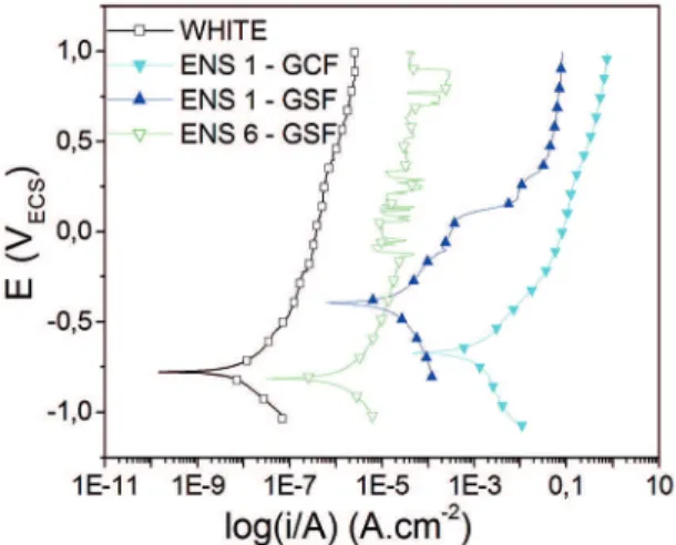
Figure 3 shows the polarization curves for the samples of thin ilms deposited on silicon for the condition of test 1, both for the cage with hole (ENS.1:GCF) and for the cage without hole (ENS.1:GSF), and of test 6 for the cage without hole (ENS.6:GSF) and for white (silicon with no ilm deposited).
Figure 3: Polarization curves of the thin ilms of tests 1, 6, and white.
Considering the analysis of Figure 3, it is observed that among the curves of the ilms, the green graph (ENS.6:GSF) showed corrosion potential (-0.7 V) and current density closer to white, which is a sample of silicon with no ilm deposition. The corrosion potential of this sample difers slightly from the corrosion potential of white; however, the current density is two orders of magnitude greater than white. On the other hand, the dark blue graph (ENS.1:GSF) showed the most noble corrosion potential (-0.3 V) and a current density 3 orders of magnitude greater than white. According to Wolynec7, the low current density and the high corrosion potential are desirable anodic characteristics in a material for this material to have a high resistance to corrosion. Therefore, it is observed that the white, despite not presenting the most noble corrosion potential, presents the best results in terms of current density. Among the ilms, it can be observed that the ilm ENS.1:GSF showed better results in terms of corrosion potential, and the ilm ENS.6:GSF was better in terms of current density. Despite the samples with deposited ilms presenting a greater current density than that of white, these values are quite satisfactory, since they are very close to the density values of white, which leads us to consider that these ilms have high resistance to corrosion. It is noteworthy that we are conducting our comparisons in relation to a semiconductor that is widely used in the market.
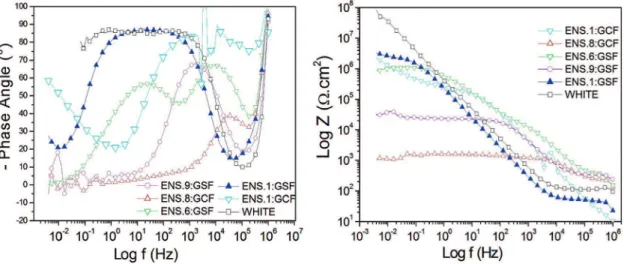
Figure 4 shows the Nyquist plots for the samples of tests: 1(GCF and GSF), 2(GCF), 3 (GSF), 6 (GSF), 8 (GCF), 9 (GSF), and white, in this order, obtained in a solution of
Figure 4: Nyquist plot obtained in chloride medium for the samples of tests 1 (GSF and GCF), 2 (GCF), 3 (GSF), 6 (GSF), 8 (GF), 9 (GSF),and white.
3.5% NaCl by mass. In these plots, it can be veriied that the ilms have very distinct capacitive and resistive behaviors.
The ilms of ENS.2:GCF and ENS.3:GSF presented a highly resistive behavior, indicating that these materials have high resistance to the passage of current and present a very low charge storage capacity. The ilms of ENS.9:GSF, ENS.8:GCF,and ENS.6:GSF are also resistive, however in lower intensity if compared with the ilms of tests 2 and 3, while the samples ENS.1:GSF and ENS.1:GCF and white are more capacitive, i.e., they can store charges, although they also present resistive behavior, as shown in Figure 5.
1101 Electrochemical Behavior of Titanium Nitride Thin Films Deposited on Silicon by Plasma Discharge
Technique in Cathodic Cage
Figure 5: (a) – Bode plot of the phase angle versus logarithm of frequency for the samples of tests 1 (GSF and GCF), 2 (GCF), 3(GSF), 6 (GSF), 8 (GCF), 9 (GSF),and white
therefore presenting high resistance to corrosion, although the sample ENS.1:GCF has also shown this decrease in the high-frequency region.
The analysis of Figure 4(b) enables the observation that the ilms of ENS.8:GCF and ENS.9:GSF presented the lowest values of Z in relation to white and, thus, have lower surface resistance to passage of current. It is also observed that the sample ENS.8:GCF has the lowest surface resistance of all the samples, while ENS.1:GSF has the highest surface resistance of all the other samples. These results demonstrate the capacity of the technique to deposit ilms with high resistance to corrosion. Additionally, it enables coating noble materials at low cost, making them high-performance materials.
4. Conclusions
In all the process conditions studied, it was possible to obtain thin ilms with highly varied anodic properties. This conirms the eiciency of the plasma deposition technique using cathodic cage. The coniguration of the cages, the presence or absence of holes on the sides, the gas atmosphere, and the treatment temperature inluence the deposition process and, hence, the properties of the thin ilms formed. These diferences, especially in relation to the holes of the cage, inluenced the electrochemical properties, because the ilms had both capacitive and resistive behavior for the conditions analyzed in these two cages. It is still necessary to know the range of possibilities of this technique. Therefore, further research is already being conducted based on this work and on those of Universidade Federal do Rio Grande do Norte (UFRN), which, to date, are the only ones in the literature on deposition of thin ilms by plasma using cathodic cage.
5. Acknowledgements
The authors thank Capes and Ifes for the inancial support for the translation of this article, and the Postgraduation Program in Metallurgical and Materials Engineering from Instituto Federal do Espírito Santo (PROPEMM/IFES).
6. References
1. Sousa RRM, Araújo FO, Ribeiro KJB, Sousa RS, Costa JAP, Alves Jr C. Post-discharge nitriding of AISI 316 steel samples with
diferent dimensions. In: 17th CBECIMat - Brazilian Congress
of Engineering and Materials Science; 2006 Nov 15-19; Foz do Iguaçu, PR, Brazil.
2. Daudt NF, Barbosa JCP, Macêdo MOC, Pereira MB, Alves Jr C. Efect of cage coniguration in structural and optical properties
of TiN ilms grown by cathodic cage discharge. Materials
Research. 2013;16(4):766-771.
3. Daudt NF, Barbosa JCP, Macêdo MOC, Nascimento Neto AB, Guerra Neto CLB, Alves Jr C. Feasibility of plasma in discharge of cathodic cage technique for obtaining of TiN ilms
for biocompatible coatings. Revista Brasileira de Inovação
Tecnológica em Saúde.2012;2(2):16-24.
4. Peng Z, Miao H, Qi L, Yang S, Liu C. Hard and wear-resistant titanium nitride coatings for cemented carbide cutting tools
by pulsed high energy density plasma. Acta Materialia.
2003;51(11):3085-3094.
5. Meng LJ, dos Santos MP. Characterization of titanium nitride ilms prepared by D.C. reactive magnetron sputtering at diferent nitrogen pressures. Surface and Coatings Technology. 1997;90(1-2):64-70. 6. Massiani Y, Medjahed A, Gravier P, Argème L, Fedrizzi L.
Electrochemical study of titanium nitride ilms obtained by
reactive sputtering. Thin Solid Films. 1990;191(2):305-316.
7. Wolynec S. Técnicas Eletroquímicas em Corrosão. São Paulo: