Article
J. Braz. Chem. Soc., Vol. 22, No. 9, 1808-1815, 2011. Printed in Brazil - ©2011 Sociedade Brasileira de Química 0103 - 5053 $6.00+0.00
A
*e-mail: [email protected]
Dansyl-Based Fluorescent Films Prepared by Chemical and Electrochemical
Methods: Cyclic Voltammetry, AFM and Spectroluorimetry Characterization
Ana Julia C. Silva,a José Ginaldo Silva Jr.,b Severino Alves Jr.,c Josealdo Tonholoa and
Adriana S. Ribeiro*,a
aInstituto de Química e Biotecnologia, Universidade Federal de Alagoas,
Campus A. C. Simões, Tabuleiro do Martins, 57072-970 Maceió-AL, Brazil
bInstituto Federal de Alagoas, Rua Lourival Alfredo 176, Poeira,
57160-000 Marechal Deodoro-AL, Brazil
cDepartamento de Química Fundamental, Universidade Federal de Pernambuco,
50670-901 Recife-PE, Brazil
Filmes luorescentes baseados em derivados de dansila foram preparados a partir de duas metodologias diferentes. Em uma delas, a superfície de um eletrodo de óxido de índio dopado com estanho (ITO) foi coberta com um ilme de quitosana e o polímero foi posteriormente derivatizado com cloreto de dansila, enquanto que na outra metodologia, um ilme de dansilglicina foi depositado eletroquimicamente sobre ITO. A técnica de microscopia de força atômica (AFM) foi usada para mapear a superfície dos ilmes. A comparação das propriedades eletroquímicas, fotoquímicas e morfológicas destes ilmes indicou que o ilme de dansilglicina depositado eletroquimicamente sobre ITO apresentou resposta eletroquímica, nível de luorescência mais intenso, maior rugosidade supericial e maior área supericial relativa em comparação com o seu homólogo quitosana-cloreto de dansila. Esse comportamento pode ser atribuído ao maior número de sítios ativos presentes na estrutura bem organizada do ilme eletrodepositado em comparação com os ilmes produzidos quimicamente.
Dansyl-based luorescent ilms were prepared by two different methods. In one of them, the surface of an indium tin oxide (ITO) electrode was coated with a ilm of chitosan and the polymer subsequently derivatized with dansyl chloride, whilst in the second method a ilm of dansylglycine was electrochemically deposited on the ITO surface. Atomic force microscopy (AFM) was employed to map the surfaces of the ilms. Comparison of the morphological, photochemical and electrochemical properties of these ilms indicated that the dansylglycine ilm electrodeposited on ITO exhibited electrochemical response, emitted a higher level of luorescence, presented greater surface roughness and larger relative surface area in comparison with its dansyl chloride-chitosan counterpart. This behavior can be attributed to the higher number of active sites present in the well-organized and rough structure of the electrodeposited ilm in comparison with the chemically produced ilms.
Keywords: luorescent ilms, chitosan, dansyl derivatives, atomic force microscopy
Introduction
Surface immobilization of organic molecules on various solid supports to prepare thin ilms with desired properties has gained considerable research interest in the past few decades.1 This is because, on one hand, it can offer model systems to study surface-dependent phenomena
like catalysis,2 adhesion,3 or wetting,4 and, on the other hand, it plays a great role in the design and preparation of functionalized surface materials.5,6 The photochemical, photophysical and electrochemical properties of these functional ilms offer a wide range of potential applications in nonlinear optics,7 displays,8,9 biomedicine and chemical sensors.10
selectivity, once such ilms are reusable and are readily fabricated into devices.6 Some special fluorophores, which may have two parts in their structures, namely, the donor part and the acceptor part connected by a single bond, can present twisted intra-molecular charge transfer (TICT) phenomenon.11 When excited, the donor part of the luorophore may rotate around the single bond and transfer an electron to the acceptor part. As a result, the molecular structure of the luorophore changes from a planar conformation to a perpendicular conformation, exhibiting two excited states, one is the TICT state and the other is the non-charge transfer state (non-CT state). TICT phenomenon has been reported for luorophores immobilized on a substrate surface by Ding et al.,1 giving a new approach for designing novel functional ilms.
TICT phenomenon can occur in the derivatives of 1-(dimethylamino)-naphthalene-5-sulfonyl), usually called dansyl (Figure 1), in which dimethylamino moiety functions as a donor part and naphthalene sulfonyl as an acceptor part. The dansyl luorophore exhibits intense absorption bands in the near UV and a strong luorescence in the visible region with high emission quantum yields.12 These characteristics, together with the synthetic lexibility of the sulfonyl group, have led the dansyl luorophore to be a core-structure present in many luorescent sensors and labels for the detection of both metal cations13-15 and anions,16,17 as well as in larger supramolecular structures such as dendrimers.18,19
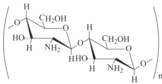
The present paper describes the preparation of luorescent ilms of a dansyl luorophore immobilized on a polymer substrate. Due to its good ilm forming property and ease to be modiied,20,21 chitosan is as an ideal substrate for preparation of functional ilms. Chitosan (Figure 2) is a biopolymer produced by partial deacetylation of chitin, derived from crustacean shells and is a member of the family of linear copolymers of 2-acetamido-2-deoxy-β-D-glucopyranose and 2-amino-2-deoxy-β-D-glucopyranose.21-23 Chitosan and its derivatives are currently being studied for potential uses in such diverse ields as drug and gene delivery24,25 enzyme immobilization,26 polymer batteries,27 antimicrobial effect28 and metal ion removal from aqueous solutions.29
Fluorescent chitosans can be obtained by the attachment of luorescent groups to a polymer backbone30,31 or by the incorporation of several organic or inorganic materials, including transition metal ions, into the chitosan matrix.32-34 Numerous works have been recently published about the synthesis and characterizations of luorescent chitosans based on luorescent dyes. The interest for these materials is justiied by the applications as luminescent probes to study the structure of polymeric matrices or to understanding the behavior of biological macromolecules and also as sensors in a great range of ields.23,31,35,36
In this work, chitosan was selected as a substrate and dansyl derivatives as luorophore element to design and prepare a new kind of luorescent ilms, which can be applied as an emitting layer in organic electroluminescent devices,37 since the photophysical properties related to intra-molecular charge transfer are useful for electroluminescence application. These ilms were prepared by two different methods: (i) chemical immobilization of dansyl chloride in a chitosan matrix coated onto an indium tin oxide (ITO) surface or (ii) electrodeposition of dansylglycine ilms on the ITO surface. The morphological, photochemical and electrochemical parameters of these ilms were determined and compared aiming purpose the appropriate deposition method according to the projected application for the functionalized ilm.
Experimental
Materials and instruments
Chitosan (Acros; MW 100,000-300,000), dansyl chloride (Sigma-Aldrich), dansylglycine (Sigma-Aldrich) and LiClO4 (Vetec) were used as supplied without further puriication. CH3CN (H2O < 0.001%, Sigma-Aldrich) was distilled over P2O5 prior to use. ITO electrodes (1.0 cm
2,
Rs ≤ 10 Ω cm2; Delta Technologies) were employed as substrate for the chemical and electrochemical deposition of luorescent ilms.
Electrochemical depositions and characterizations were performed in an Autolab PGSTAT30 galvanostat/
Figure 1.Molecular structure of dansyl luorophore: R = Cl (dansyl chloride) or R = NHCH2COOH (dansylglycine).
potentiostat. A platinum plate (1.0 cm2) was used as the counter electrode and a non-aqueous Ag/Ag+ (CH
3CN) electrode (+0.298 V vs. normal hydrogen electrode), isolated from the working solution by a Vycor® frit, was used as reference.
Fluorescence spectra were measured at dry state (room temperature) using an ISS K2 Multifrequency Phase Fluorometer equipped with a 300 W xenon lamp and holographic grating (excitation), and a 25 cm monochromator (0.1 mm resolution) and photomultiplier (emission). The excitation and emission monochromators were operated at slit widths of 0.5 mm, both monochromators having 1200 grooves mm-1. The excitation spectra were obtained with a linear light beam whilst emission spectra were obtained at an angle of 34o between the light beams.
Atomic force microscopy (AFM) images were acquired using a Shimadzu SPM-9500J3 microscope with a scanner of 125 µm on the x-y plane and 8 µm along the z axis. The instrument was operated in the contact mode and was controlled by SPM Manager software (version 2.11). The cantilevers were needles of Si3N4 (200 µm length; Olympus) with a resonance frequency of 24 kHz and a spring constant of 0.15 N m-1.
Preparation of dansyl chloride-chitosan ilms
An aliquot (100 µL) of a 1% (m/v) chitosan solution (prepared by dissolving 0.05 g of chitosan in 5.0 mL of 0.25 mol L-1 acetic acid) was distributed homogenously over the surface of an ITO electrode (1.0 cm2) treated with the RCA protocol.38,39 The coated plate was carefully transferred to a covered container, allowed to dry for 48 h at room temperature, and then immersed in a solution of dansyl chloride (0.012 g) in dry CH3CN (15.0 mL) for 48 h at room temperature. After reaction, the electrode was rinsed several times with dry CH3CN and dried at room temperature for 24 h.
Electrodeposition of dansylglycine ilms
Films were electrodeposited on ITO electrodes (1.0 cm2) from a solution containing 0.002 mol L-1 of dansylglycine and 0.1 mol L-1 LiClO
4 (as supporting electrolyte) in freshly distilled CH3CN. Potentiodynamic method was employed in which the potential varied from 0.0 V to −1.8 V vs. Ag / Ag+ at a scan rate (ν) of 0.020 V s-1, and the number of voltammetric cycles was varied between 2 and 5 in order to optimize the deposition conditions. Deposited ilms were washed several times with CH3CN to remove unreacted dansylglycine and excess of supporting electrolyte.
Morphological and electrochemical characterization of the ilms
The surfaces of the chitosan, dansyl chloride-chitosan and electrodeposited dansylglycine ilms were scanned by AFM over areas measuring 10 × 10 µm at a maximum scan rate of 1.0 Hz and at resolutions of above 512 × 512 lines. The mapped surface images were processed by lattening to best it the inclination, contrast and brightness.
Cyclic voltammograms of the dansyl derivatives ilms were registered in a potential range of −0.6 to 0.1 V,
ν = 0.02 V s-1, using a LiClO
4 / CH3CN 0.1 mol L
-1 solution
as electrolyte.
Results and Discussion
Electrochemical characterization of dansyl derivatives and electrodeposition of dansylglycine ilms
Cyclic voltammograms showing the electrochemical behavior of the dansyl chloride and dansylglycine derivatives in LiClO4 / CH3CN in the anodic and cathodic regions are displayed in Figure 3 and Figure 4, respectively. According to the functional groups present in the molecular structure of dansyl chloride and dansylglycine, the following electrochemical reactions can be possible in aprotic media: (i) the anodic oxidation of the tertiary amine at the range of 0.6 to 1.5 V, depending on the substituent,40-42 (ii) the electroreduction of the carboxylic acid (just for the dansylglycine) at ca. −1.5 V, giving carboxylate anions that can rearrange and form a series of different products42 and (iii) at more cathodic potential (above −2.0 V), the sulfonyl chloride S−Cl or the sulfonamide S−N bond cleavage.43,44
In the anodic region, the cyclic voltammograms revealed an irreversible peak at 0.706 V for the dansyl
Figure 3. Cyclic voltammograms of dansylchloride (---) and dansylglycine (—) in 0.1 mol L-1 LiClO
chloride and at 0.654 V vs. Ag / Ag+ for the dansylglycine (Figure 3). These peaks were attributed to the tertiary amine oxidation of both derivatives, suggesting a fast following coupled chemical reaction and/or an irreversible charge transfer reaction, but with no signiicant changes observed at the electrode surface.
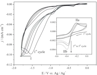
Figure 4 displays the cyclic voltammograms acquired during the cycling in the potential range of 0.0 to −1.8 V. The first voltammetric scan of the dansylglycine in LiClO4 / CH3CN showed and irreversible peak (I) at −1.537 V, that can be assigned to the carboxylate anion or anion radical generation with expected consecutive chemical steps, resulting in self-protonation45 or side reactions giving dimers or oligomers onto the ITO surface.42 The reverse scan showed another peak (IIa) at −0.209 V, related to the oxidation of the product generated after the irst reduction step, once peak IIa was not present when the cathodic scan range was limited to −1.0 V. Furthermore the successive cycling evidenced the displacement of the peak I to more cathodic potentials (ca. −1.8 V) and also the appearance of a new peak (IIb) at −0.374 V, identiied as the correspondent reduction of IIa.
Attempts to deposit dansyl chloride by electrochemical methods were performed using the same experimental conditions used to deposit dansylglycine, however, the ilm formation on the ITO surface was not observed. A possible explanation for this behavior is that deposition of dansyl derivatives is conditioned by the reduction of the carboxylic acid group present in the dansylglycine.
Concerning the discussions about the electrochemical behaviour of the dansyl derivatives, there are few works published in the literature. In their work, Fontanesi et al.,46 investigated the reduction of tosylglycine and dansylglycine
in several solvents by polarographic measurements using Hg electrode and proposed the formation of carboxylate anions in aprotic media. Another paper, published by Illos et al.,47 describes the synthesis of a new dansyl derivative bearing a carbazoloquinone moiety for apply this system as an electrochemical luorescent switch, but these authors focused the data interpretation just for the electrochemical response of the quinone-hydroquinone redox pair.
Electrochemical characterization of the dansylglycine and dansyl chloride-chitosan ilms
Cyclic voltammograms of the two immobilized dansyl ilms, recorded in LiClO4 / CH3CN as supporting electrolyte, are presented in Figure 5. The electrochemically deposited dansylglycine ilm (full line) exhibited a shoulder at −0.228 V, not visualized during the electrodeposition process, and a redox pair with cathodic peak potential (Epc) at −0.389 V and anodic peak potential (Epa) at −0.092 V vs. Ag/Ag+. This is a classical behavior of an electroactive film, with cathodic integrated charge of
ca. 24 mC cm-2. The chemically formed dansyl chloride-chitosan ilm showed no electrochemical response over the potential range investigated (dash line), justiied by the ITO electrode passivation by the chitosan ilm.
Morphological characterization
Representative two- and three-dimensional AFM images of chitosan and dansyl chloride-chitosan ilms are portrayed in Figures 6A and 6B, respectively. The chitosan ilm presented a plain homogeneous surface exhibiting very low dispersion in the roughness proile, whilst the dansyl chloride-chitosan film displayed a non-homogeneous
Figure 4. Cyclic voltammograms registered during the electrodeposition of the dansylglycine ilms on ITO in 0.1 mol L-1 LiClO
4 / CH3CN with
ν = 0.020 V s-1.
Figure 5. Cyclic voltammograms of dansylchloride-chitosan (---) and dansylglycine (prepared with 5 voltammetric cycles) (—) ilms deposited on ITO electrodes in 0.1 mol L-1 LiClO
surface with some roughness. Evidently, expressive modifications to the film surface occurred during the reaction between the dansyl chloride and the amino groups of the chitosan, giving a luorescent ilm deposited onto the ITO surface, due to the sulfonamide formation.
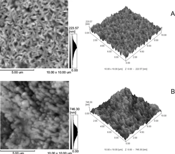
AFM images of dansylglycine films deposited electrochemically on ITO electrodes with 3 and 5 voltammetric cycles are depicted, respectively, in Figures 7A and 7B. These ilms presented well-organized rice-grain type structures exhibiting high dispersion in the roughness proile. In ilms electrodeposited with 3 voltammetric cycles, the grains grew to ca. 400-500 nm in length and 100 nm in diameter, and most of them were orientated in the co-planar direction (Figure 7A). In contrast, the grains of the ilms produced with 5 voltammetric cycles showed a tendency to grow in the vertical direction, forming polyp-like structures with thicknesses of ca. 200-300 nm and heights of 600-700 nm (Figure 7B). It is thus clearly possible to control both thickness and morphology of electrodeposited dansylglycine films by adjusting the
number of voltammetric cycles, which is related to the deposition charge (Qdep).48
The arithmetic mean roughness (Ra), the square average roughness (Rms) and the relative surface area of the chitosan, dansylchloride-chitosan and electrodeposited dansylglycine ilms, are presented in Table 1. These data indicate that the morphological parameters vary markedly as a function of the deposition method used to obtain the luorescent ilm, as can be seen in the luorescent emissions when exposed to ultraviolet light irradiation (366 nm), of the dansyl chloride-chitosan ilm and of the electrodeposited dansylglycine ilm (dry condition). It may be observed that the electrodeposited dansylglycine film, which exhibited higher roughness parameters and a larger relative surface area, exhibited a very much stronger luorescence emission under ultraviolet light.
Steady state luorescence
The steady-state excitation and emission luorescence spectra of the dansyl chloride-chitosan and electrodeposited
dansylglycine functional ilms at dry state are shown in Figures 8A and 8B, respectively.
The emission spectra of the electrodeposited dansylglycine ilm consist of two bands, of which one situates at 435 nm, named as band B, and the other at 450 nm, named as band A. According to the model proposed by Ding et al.,6 dansyl in the immobilized state exists mainly in lonely monomer state. When the luorophore is excited, three excited states would be formed and decay differently. The lifetime of non-CT excited state is shorter because it is less stable than the
others. Emission from this excited state occurs at shorter wavelengths, and it is the so-called band B. The lifetime of TICT excited state is longer than that of non-CT, then emission of it occurs at longer wavelength, and it is the so-called band A. In this way, the dual luorescence may be attributed to the emission from the locally excited or the non-CT state (emission at 435 nm) and that from the TICT state (emission at longer wavelength), respectively. Based on this result, we drew a conclusion that there exists a TICT state for dansylglycine electrochemically immobilized on the ITO surface.
Table 1. Values of arithmetic mean roughness (Ra), square average roughness (Rms) and relative surface area of a chitosan ilm, a dansylchloride-chitosan
ilm and electrodeposited dansylglycine ilms
Film Ra / nm Rms / nm Relative surface area
Chitosan 1.506 2.172 1.001
Dansylchloride-chitosan ilm 6.317 8.036 1.005
Electrodeposited dansylglycine with 3 voltammetric cycles 24.11 30.38 1.063
Electrodeposited dansylglycine with 5 voltammetric cycles 86.60 105.5 1.207
Figure 8. Fluorescence excitation scan spectra (A) and luorescence emission scan spectra (B) of ilms of dansylchloride-chitosan (---) and dansylglycine (prepared with 5 voltammetric cycles) (—) deposited on ITO.
The dansyl chloride-chitosan (Figure 8, dash line) ilm showed only one symmetric emission band with slight differences in the position of the maximum luorescence intensity (red shift) with respect to the electrodeposited dansylglycine ilm (Figure 8, full line). This behavior can be justiied in terms of the solid state stabilization of dansyl groups by chitosan, once this polymer has a multifunctional molecular structure containing large numbers of amine groups, which is easy to react with dansyl chloride. After the reaction, the sulfonyl chloride group in the luorophore must be converted into sulfonamide, which is a strong electron-withdrawing group and favors formation of TICT state when the luorophore is excited.49 However, as it was observed only one emission band in the dansyl chloride-chitosan ilm luorescence spectrum, TICT phenomenon was not observed in this case. Probably, the second band, characteristic of the TICT, was quenched due to the presence of water residue in chitosan ilm.
Furthermore, the emission bands are well separated from the excitation ones, showing a Stokes shift of 115 and 120 nm for electrodeposited dansylglycine and dansyl chloride-chitosan ilms, respectively. The magnitude of the Stokes shift of the ilm depends on the nature of the environment, by which the ilm is surrounded.50
Conclusions
Films employing the dansyl group as luorophore may be readily prepared using chemical or electrochemical methods and exhibit two fundamental characteristics, namely, electrochemical response and visible light fluorescence. It has been shown that, together with fluorimetric and electrochemical characterization,
determination of the morphological parameters of a ilm provides a useful tool by which to deine the appropriate deposition method according to the projected application for the material, i.e. as an emitting layer in organic electroluminescent devices or as a sensor.
Acknowledgements
The authors wish to thank the Brazilian granting authorities Conselho Nacional de Desenvolvimento Cientíico e Tecnológico (CNPq), Fundação de Amparo à Pesquisa do Estado de Alagoas (FAPEAL), Financiadora de Estudos e Projetos (FINEP) and Coordenação de Aperfeiçoamento de Pessoal de Nível Superior (CAPES) for inancial support and for fellowships to A. J. C. S. (CAPES). The authors are also grateful to Instituto Nacional de Ciência e Tecnologia (INCT-INAMI) and to Braskem Co. (Brazil) for partnership in technological development and to Gleidson P.O. Silva for technical contributions.
References
1. Ding, L.; Kang, J.; Lu, F.; Gao, L.; Yin, X.; Fang, Y; Thin Solid Films2007, 515, 3112.
2. Kakkar, A. K.; Chem. Rev.2002, 102, 3579.
3. Roberts, C.; Chen, C. S.; Mrksich, M.; Martichonok, V., Ingber, D. E.; Whitesides, G. M.; J. Am. Chem. Soc.1998, 120, 6548. 4. Atre, S. V.; Liedberg, B.; Allara, D. L.; Langmuir1995, 11,
3882.
5. Zhang, C.; Luo, N.; Hirt, D. E.; Polymer2005, 46, 9257. 6. Ding, L.; Fang, Y.; Jiang, L.; Gao, L.; Yin X.; Thin Solid Films
2005, 478, 318.
7. Li, D. Q.; Swanson, B. I.; Robinson, J. M.; Hoffbauer, M. A.;
J. Am. Chem. Soc. 1993,115, 6975.
8. Zhang, L.; Zheng, X.; Anal. Chim. Acta2006, 570, 207. 9. Jin, Y.; Kim, J. Y.; Park, S. H.; Kim, J.; Lee, S.; Lee, K.;
Suh, H.; Polymer 2005, 46, 12158.
10. Fujiwara, Y.; Amao, Y.; Sens. Actuators, B2002, 85, 175. 11. Hayashi, Y.; Kawada, Y.; Ichimura, K.; Langmuir1995, 11,
2077.
12. Parola, A. J.; Lima, J. C.; Pina, F.; Pina, J.; De Melo, J. S.; Soriano, C.; García-España, E.; Aucejo, R.; Alarcón, J.; Inorg. Chim. Acta 2007, 360, 1200.
13. Metivier, R.; Leray, I.; Lebeau, B.; Valeur, B.; J. Mater. Chem.
2005, 15, 2965.
14. Prodi, L.; Montalti, M.; Zaccheroni, N.; Dallavalle, F.; Folessani, G.; Lanfranchi, M.; Corradini, R.; Pagliari, S.; Marchelli, R.;
Helv. Chim. Acta2001, 84, 690.
15. Ding, L.; Cui, X.; Han, Y.; Lu, F.; Fang, Y.; J. Photochem. Photobiol., A2007, 186, 143.
17. Liu, S.-Y.; He, Y.-B.; Qing, G.-Y.; Xu, K.-X.; Qin, H.-J.;
Tetrahedron: Asymmetry 2005, 16, 1527.
18. Ceroni, P.; Vicinelli, V.; Maestri, M.; Balzani, V.; Lee, S.K.; van Heyst, J.; Gorka, M.; Vogtle, F.; J. Organomet. Chem. 2004,
689, 4375.
19. Mohanty, S. K.; Baskaran, S.; Mishra, A.K.; Eur. Polym. J.
2006, 42, 1893.
20. Jiang, Z.; Yu, Y.; Wu, H.; J. Membr. Sci. 2006, 280, 876. 21. Notin, L.; Viton, C.; David, L.; Alcouffe, P.; Rochas, C.;
Domard, A.; Acta Biomater.2006, 2, 387.
22. Thanpitcha, T.; Sirivat, A.; Jamieson, A. M.; Rujiravanit, R.;
Carbohydr. Polym.2006, 64, 560.
23. Tommeraas, K.; Strand, S. P.; Tian, W.; Kenne, L.; Varuma, K. M.;
Carbohydr. Res. 2001, 336, 291.
24. Han, H. D.; Song, C. K.; Park, Y. S.; Noh, K. H.; Kim, J. H.; Hwang, T.; Kim, T. W.; Shin, B. C.; Int. J. Pharm. 2008, 350, 27.
25. Weecharangsan, W.; Opanasopit, P.; Ngawhirunpat, T.; Apirakaramwong, A.; Rojanarata, T.; Ruktanonchai, U.; Lee, R. J.; Int. J. Pharm. 2008, 348, 161.
26. Li, W.; Yuan, R.; Chai, Y.; Zhou, L.; Chen, S.; Li, N.; J. Biochem. Biophys. Methods2008, 70, 830.
27. Ng, L. S.; Mohamad, A. A.; J. Power Sources2006, 163, 382. 28. Rhoades, J.; Roller, S.; Appl. Environ. Microbiol.2000, 66, 80. 29. Paulino, A. T.; Santos, L. B.; Nozaki, J.; React. Func. Polym.
2008, 68, 634.
30. Fernandes, S. C. M.; Freire, C. S. R.; Silvestre, A. J. D.; Pascoal Neto, C.; Gandini, A.; Desbrières, J.; Blanc, S.; Ferreira, R. A. S.; Carlos, L. D.; Carbohydr. Polym.2009, 78, 760. 31. Munro, N. H.; Hanton, L. R.; Robinson, B. H.; Simpson, J.;
React. Func. Polym.2008, 68, 671.
32. Lee, Y.-H.; Chang J.-J.; Lai, W.-F.; Yang, M.-C.; Chien C.-T.;
Colloids Surf., B 2011, 86, 409.
33. Yan, E.; Wang, C.; Wang, S.; Sun, L.; Wang, Y.; Fan, L.; Zhang, D.; Mater. Sci. Eng., B2011, 176, 458.
34. Xia, H.; He, G.; Peng, J.; Li, W.; Fang, Y.; Appl. Surf. Sci.2010,
256, 7270.
35. Mi, F.-L.; Shyu, S.-S.; Peng, C.-K.; J. Polym. Sci., Part A: Polym. Chem. 2005, 43, 1985.
36. Zhang, S.-J.; Fang, Y.; Hu, D.-D.; Gao, G.-L.; Chin. J. Chem.
2003, 21, 249.
37. Kalinowski, J.; Optical Materials2008, 30, 792.
38. Kim, J. S.; Granstrom, M.; Friend, R. H.; Johansson, N.; Salaneck, W. R.; Daik, R.; Feast, W. J.; Cacialli, F.; J. Appl. Phys. 1998, 84, 6859.
39. Armstrong, N. R.; Cartera, C.; Donley, C.; Simmonds, A.; Lee, P.; Brumbash, M.; Kippelen, B.; Domercq, B.; Yoo, S.;
Thin Solid Films2003, 445, 342.
40. Chiu, K. Y.; Su, T. X.; Li, J. H.; Lin, T.-H.; Liou, G.-S.; Cheng, S.-H.; J. Electroanal. Chem.2005, 575, 95.
41. Cruickshank, A. M.; Tan, E. S. Q.; Brooksby, P. A.; Downard, A. J.; Electrochem. Commun.2007, 9, 1456.
42. Lund, H.; Hammerich, O.; Organic Electrochemistry, 4th ed.;
Marcel Dekker, Inc.: New York, 2001.
43. Angelo, A. C. D.; Jorge, S. M. A.; Stradiotto, N. R.; Eclét.Quím.
2005, 30, 57.
44. Dubey, S.; Fabre, B.; Marchand, G.; Pilard, J.-F.; Simonet, J.;
J. Electroanal. Chem.1999, 477, 121.
45. Azevedo, D. C.; Boodts, J. F. C.; Cavalcanti, J. C. M.; Santana, A. E. G.; dos Santos, A. F.; Bento, E. S.; Tonholo, J.; Goulart, M. O. F.; J. Electroanal. Chem.1999, 466, 99.
46. Fontanesi, C.; Borsari, M.; Andreoli, R.; Benedetti, L.; Grandi, G.; Gavioli, G. B.; Electrochim. Acta1989, 34, 759. 47. Illos, R. A.; Shamir, D.; Shimon, L. J. W.; Zilbermann, I.;
Bittner, S.; Tetrahedron Lett.2006, 47, 5543.
48. Ribeiro, A. S.; Nogueira, V. C.; Santos, P. F.; De Paoli, M.-A.;
Electrochim. Acta 2004, 49, 2237.
49. Grabowski, Z. R.; Rotkiewicz, K.; Retting, W.; Chem. Rev.
2003, 103, 3899.
50. Olmos, D.; Lopez-Moron, R.; Gonzalez-Benito, J.; Compos. Sci. Technol.2006, 66, 2758.