Surface Properties Contrast between Al Films and TiO
2Films Coated on Magnesium Alloys
by Magnetron Sputtering
Xiangrong Zhua*, Zhigang Zhua, Cheng Chena, Naici Binga, Zhongping Xua, Yang Lia,
Qiurong Chenb
Received: September 30, 2016; Revised: December 30, 2016; Accepted: January 25, 2017
Al ilms and TiO2 ilms were separately coated on AZ31 magnesium alloy substrates by means
of magnetron sputtering method. The surface properties of the samples were explored and compared. Scanning electron microscope (SEM) observed the compact structure characteristics of as-deposited Al ilms and TiO2 ilms. After heat treatment under 200ºC for half an hour the ilms kept the compact structure
characteristics and there didn’t exist structural defects on the surface of the ilms. Nano-indentation
measurement results display that the micro-hardness of as-deposited Al ilm and TiO2 ilm reaches
about 1.90 Gpa and 1.51 Gpa, separately. Al ilm is a bit harder than TiO2 ilm. Finally, the corrosion
experiments in simulated body luid initially indicate the diferent corrosion properties for Al ilm and TiO2 ilm. Al ilm presents more efective anti-corrosion properties than TiO2 ilm.
Keywords: Surface properties, Magnesium alloy, Al ilms, TiO2 ilms, Magnetron sputtering
* e-mail: [email protected]
1. Introduction
For several decades, as excellent light metal and structural materials, magnesium alloys have been widely used in industrial ields such as transportation, building, electronic products, etc1-8. Furthermore, because of non-toxic
properties and good biocompatibility, magnesium alloys are increasingly focused on the biomedical ield9-11. However,
the surface properties of traditional magnesium alloys are usually unsatisfactory. For example, their anti-corrosion properties are poor, wear resistance is commonplace and and temperature stability is low, which might result in great limitation to their further application9-13. Then the surface
modiication on the magnesium alloys is necessary for improving their properties.
The object of surface modiication of magnesium alloys is to prepare one coating layer on the surface. Multiple approaches have been explored to synthesize the coating layer on the surface of magnesium alloy, including anodic or microarc oxidation3,5,14, magnetron sputtering4,6,cathodic
arc deposition12, friction stir welding with polymer coating15,
etc. Except magnetron sputtering, the aims of the above techniques are synthesizing compact oxidation layer on the surface of magnesium alloys by means of complicated chemical or electrochemical reaction. So the quality of modiication is related to the contents of metal elements and deposition conditions. Comparatively, magnetron sputtering
is one kind of physical vapor deposition technique to grow ilms on substrates, which is convenient and economical for operation with less environmental pollution. There are two working modes for magnetron sputtering. One is dc mode, the other is rf mode. Dc mode is always adopted to deposit metallic ilms. Rf mode is used for depositing oxide ilms. Usually the ilms deposited by magnetron sputtering present good uniformity and desirable properties4,6.
Due to high hardness and non-toxic properties, TiN ilm is considered as a competitive coating layer for surface modiication on magnesium alloy11,12. Furthermore, Al ilm
presents charm for corrosion resistance4. Many studies on
structural and mechanical properties of Al ilm and TiN ilm coated on magnesium alloys were reported4,16,17. Considering
the biocompatibility of the coating materials in the iled of
medical application, TiO2 ilm might be also a desirable
choice for the modiication of magnesium alloy18.Then the
study on the surface properties of TiO2 ilm on magnesium
alloy is signiicant. Additionally, before using as biomedical materials, the degradation mechanism of the coating layers on magnesium alloys should be explored. An efective approach to exploring the degradation mechanism is to study the corrosion behaviors in Hank’s simulated body luid (SBF)9.
AZ31 is one kind of wrought magnesium alloy, which can be used as the substrates for depositing ilms. In this
paper, the deposition of Al ilms and TiO2 ilms on AZ31
magnesium alloy substrates by means of magnetron sputtering was reported. The surface properties of the ilms such as
a School of Environment and Materials Engineering, College of Engineering, Shanghai Polytechnic
University, Shanghai, 201209, China
b Shanghai Institute of Microsystem and Information Technology, Chinese Academy of Sciences,
structure characteristics and corrosion properties in simulated body luid are explored and compared detailedly.
2. Experimental Procedure
The substrates of the samples are 1 cm × 1 cm as-casted AZ 31 magnesium alloy chips with 2 mm thickness. The chips were irstly ground with SiC abrasive papers and then polished by a mechanical polishing equipment using corundum abrasive. The polished chips were cleaned in acetone by an ultrasonic cleaner, washed by deionized water and inally dried in air.
During the process of magnetron sputtering, the dried AZ31 chips were ixed onto the sample holder in the cavity of the JGP 450 magnetron sputtering equipment, which was manufactured by SKY Technology Development Co., Ltd, Chinese Academy of Sciences. The base pressure of the
cavity was 5 × 10⁻⁴ Pa, which was measured by a vacuum
ionization gauge attached within the JGP450 magnetron sputtering equipment. The substrates were not preheated. For Al samples, the sputtering mode is dc magnetron sputtering. The corresponding sputtering parameters are: 2 inches 99.99% Al disc as target, Ar as working atmosphere with pressure 0.5 Pa, sputtering time 50 minutes, sputtering power 120 W. The Ar low was maintained as 20 SCCM by a gas low meter. The Ar working atmosphere pressure was measured by a vacuum resistance gauge also attached within the JGP 450 magnetron sputtering equipment. For TiO2 samples, the
sputtering mode is rf magnetron sputtering. The corresponding
sputtering parameters are: 2 inches 99.95% TiO2 ceramic
disc as target, 0.5 Pa working atmosphere mixed with Ar and O2, sputtering time 55 minutes, sputtering power 150 W.
Firstly, for as-deposited Al ilm and TiO2 ilm samples,
the surface morphology was observed by a Shimadz SPM9600 atomic force microscope (AFM) and a Hitachi S-4800 scanning electron microscope (SEM), separately. Secondly, the surface micro-hardness of the as-deposited ilm sample was measured by a nano-indenter. Thirdly, heat stability experiments for the as-deposited ilm samples were carried out. The heat treatment process for the samples was: 200°C temperature for 30 minutes and cooling in the air. The surface morphology of the samples after heat treatment was also observed by SEM. Finally, the as-deposited Al ilm and TiO2 ilm samples were separately put into Hank’s simulated
body luid (SBF) for the study of corrosion behavior. The composition of SBF was NaCl (8.00g) + KCl (0.40g) + CaCl2 (0.14g) + NaHCO3 (0.35g) + MgCl2·6H2O (0.1g) +
MgSO4·7H2O (0.06g) + KH2PO4 (0.06g) + Na2HPO4·12H2O
(0.06g) + H2O (1L).After a few days corrosion, the samples
were taken out from the bottles and rinsed by cleaning solution
involved with CrO3 and AgNO3. The surface morphologies
of all the corroded samples were characterized by SEM too. In addition, the corrosion experiments in SBF were also conducted to the bare AZ31 magnesium alloy substrates for
the sake of comparing the corrosion properties between the coating layers and the substrates.
3. Result and discussion
The as-deposited TiO2 ilms on the AZ31 magnesium
alloys look bright and the as-deposited Al ilms present light grey. The thickness of the as-deposited ilms is about 3 µm, estimated from the section morphologies of the ilms observed by SEM. X-ray difraction (XRD) spectra of the samples reveal obvious polycrystalline structural characteristics. Figure 1 shows the XRD spectra of the as-deposited Al ilm
and TiO2 ilm samples. The difraction peaks of magnesium
alloy substrates are much stronger. However, some peaks of Al ilm and TiO2 ilm can still be distinguished. For Al ilm,
the peaks are corresponding to the (111), (200) and (220) crystal plane difraction of face centered cubic Al. For TiO2
ilm, two anatase peaks corresponding to (101) and (200) crystal plane difraction are displayed, which reveals that the TiO2 ilm is mainly composed of anatase phases. This result
should be ascribed to low deposition temperature of the ilm.
Figure 1. The XRD spectra of as-deposited Al ilm and TiO2 ilm
samples.
The surface morphologies of the as-deposited Al ilm and
TiO2 ilm observed by AFM are shown by Figure 2. The AFM
photos distinctly reveal that both of the two ilms presents lat surface. The root mean square roughness of Al ilm and
TiO2 ilm is about 10 nm and 9 nm, respectively, implying
that the crystallizing grains of Al ilm is a bit larger than those
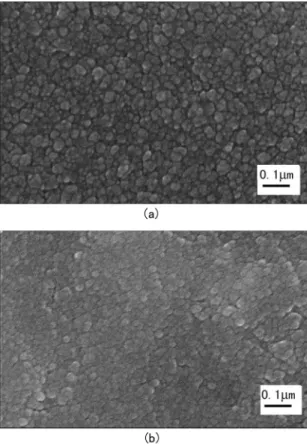
of TiO2 ilm. These facts are further demonstrated by SEM
photos of the samples displayed by Figure 3. At the same time, Figure 3 exhibits the similar surface characteristics for the two samples. Whether for Al ilm or TiO2 ilm, the grains
were uniform and the surface looks compact. There are not structural defects including cracks or holes. Wu et al. studied the microstructure of Al ilm coated on AZ91D magnesium alloy by magnetron sputtering and also observed that there
the compact structure characteristics to the similar thermal expansion coeicient between the AZ91D substrate and pure Al. Thus we deduce that for our samples, the coeicient of
thermal expansion of AZ31 magnesium alloy, Al and TiO2
might also be similar.
Figure 2. The surface morphology images of as-deposited ilms
observed by AFM (a: Al ilm. b: TiO2 ilm).
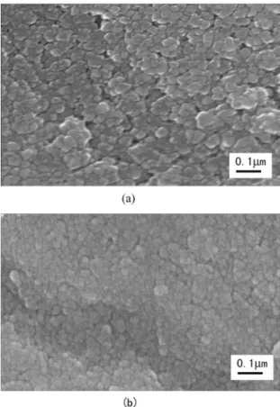
Figure 4 displays the SEM photos of the surfaces of Al
ilm and TiO2 ilm samples after heat treatment under the
heat technique mentioned above. Compared to the surface structural characteristics before heat treatment, for Al ilm sample, the grains become slightly smaller, implying that recrystallization might occur. However, for TiO2 ilm, the
size of the grains hardly changes. In addition, no defects such as cracks are observed on the surface of the samples and the surface keeps compact after heat treatment, indicating
Figure 3. The surface morphology images of as-deposited ilms
observed by SEM (a: Al ilm. b: TiO2 ilm).
that the ilms have good heat stability of structure, although the samples sufered from fast cooling process in air. These phenomena might also result from the similar coeicient of
thermal expansion of AZ 31 magnesium alloy, Al and TiO2,
as discussed above.
For investigating the micro-hardness properties of the whole surface of the ilm samples, 16 indentation points were adopted. The range of micro-hardness values is 1.49 Gpa -2.38 Gpa for Al ilm sample and 1.14 Gpa - 2.07 Gpa
for TiO2 ilm. The corresponding arithmetic average value
of the hardness of the 16 points is 1.90 Gpa for Al ilm and 1.51 Gpa for TiO2 ilm. Thus Al ilm is a bit harder than TiO2
ilm. However, the micro-hardness of either Al ilm or TiO2
ilm is much lower than that of TiN ilm by one order of
magnitude, meaning that Al ilm and TiO2 ilm have lower
wear resistance than TiN ilm 4,16,17.
Figure 4. The surface morphology images of the ilms observed by
SEM after heat treatment (a: Al ilm. b: TiO2 ilm).
in Figure 5 (a1) and Figure 5 (a2), after 3 days immersion in SBF, the crystalline structure of the magnesium alloys was destroyed under the action of SBF. Corrosion near crystalline borders is obvious. Some corrosion holes were distributed in the corrosion layer (CL). The depth of the corrosion hole is about 6 µm. After a longer corrosion time such as 10 days and 15 days, the surface of the magnesium alloy sample became wholly porous. The depth of the CL is beyond 30 µm. Even under the condition of 15 days corrosion, deeper corrosion holes appeared. These phenomena indicate the poor anti-corrosion properties of AZ31 magnesium alloys in SBF. Wang et al. studied the electrochemical corrosion behavior of bare AZ91 magnesium alloys in SBF and reported the high absolute corrosion potential of AZ91 magnesium alloys and corrosion current density19. For our work, although the
electrochemical polarization was not carried out, it could still be deduced that AZ31 magnesium would also present high absolute corrosion potential, which is responsible for the poor anti-corrosion properties in SBF.
Additionally, the magnesium corrosion reaction could be formulated by the electrochemical equation as follow20:
Mg + H2O → Mg
2+ + 2OH- + H 2
It is known that the formation of OH- ions and gaseous
hydrogen may be harmful to the life tissue20. Simultaneously
Figure 5. The surface and section morphology images of AZ31
magnesium alloy substrate observed by SEM after corrosion experiment in SBF (a, b and c are corresponding to 3 days, 10 days and 15 days corrosion, respectively. The left column of the igure is corresponding to surface morphology and the right column corresponding to section morphology).
considering the poor anti-corrosion properties, thus the bare magnesium alloys is not proper to used as biomedical materials.
The surface and section morphologies of Al ilm samples after certain corrosion procedure in SBF are shown in Figure 6. The corrosion time is also chosen as 3 days, 10 days and 15 days, separately. As shown in Figure 6 (d1) and Figure 6 (d2), after 3 days immersion in SBF, the compact structure of the ilm is lightly destroyed. The CL is not obvious. Thus the magnesium alloy substrate is prevented by Al ilm from corrosion within 3 days. However, after 10 days corrosion in SBF, many corrosion holes appeared. As displayed in Figure 6 (e2), the depth of the holes is less than 3 µm. Because the depth of as-deposited Al ilm is about 3 µm, it could be deduced that the Al ilm could still prevent the substrate from corrosion within 10 days in SBF. Finally, after 15 days corrosion in SBF, the whole surface of the sample became a CL. The depth of the CL is beyond 10 µm, meaning that the substrate itself also sufered from corrosion to some degree.
According to other reports about corrosion experiments of Al ilm in single metal salt solutions such as NaCl, a Al2O3 layer was always observed on the surface of Al ilm, implying passivation behavior of Al ilm, which would lower the corrosion speed of the ilm.21,22 In our work, the SBF
Figure 6. The surface and section morphology images of Al ilm
samples observed by SEM after corrosion experiment in SBF (d, e and f are corresponding to 3 days, 10 days and 15 days corrosion, respectively. The left column of the igure is corresponding to surface morphology and the right column corresponding to section morphology).
For TiO2 ilm sample, the surface and section morphologies
after corrosion experiment in SBF are shown in Figure 7. Here, the corrosion time is a bit diferent from that of Al ilm, which was chosen as 3 days, 7days and 10 days, respectively. Unlike the conditions of Al ilm samples, irstly, as shown in Figure 7 (g1) and Figure 7 (g2), after 3
days immersion in SBF, the compact structure of the TiO2
ilm is heavily destroyed. The corrosion holes appeared earlier, compared to the condition of Al ilm. However, the depth of the corrosion holes is less than 2 µm. Because the thickness of as-deposited TiO2 ilm is about 3 µm, it could be
referred that the magnesium alloy substrate was prevented
from corrosion by TiO2 ilm within 3 days. Wang et al
studied the corrosion behavior of microarc oxidation layer including TiO2 on AZ91 magnesium alloy substrates in SBF.
They found that the microarc oxidation layer including TiO2
presented lower absolute corrosion potential than the bare AZ91 magnesium alloys and its corrosion current density was lower than the bare AZ91 magnesium alloys by two orders of magnitude. Thus the microarc oxidation layer would prevent the AZ91 magnesium alloy substrates from sufering from corrosion in SBF in limited time. Similarly
it could be deduced that the TiO2 ilm on AZ31 magnesium
alloys should have lower absolute corrosion potential and corrosion current density than bare AZ 31 magnesium alloys, which was responsible for the improved the anti-corrosion properties of the sample in SBF.
Secondly, after 7 days immersion in SBF, the corrosion holes became larger and the depth of the holes exceeded
Figure 7. The surface and section morphology images of TiO2 ilm
samples observed by SEM after corrosion experiment in SBF (g, h and i are corresponding to 3 days, 7 days and 10 days corrosion, respectively. The left column of the igure is corresponding to surface morphology and the right column corresponding to section morphology).
3 µm, indicating that the substrate began to be corroded. Thirdly, after 10 days immersion in SBF, the whole surface
of TiO2 ilm became one CL with depth beyond 6 µm. At
the same time the magnesium alloy substrate sufered from heavier corrosion. However, compared to the condition of bare substrate, the corrosion degree is much lower for TiO2
ilm within 10 days corrosion in SBF.
In general, according to the above experiment results, the bare magnesium alloy substrates present poor anti-corrosion
properties in SBF. Both Al ilm and TiO2 ilm could hinder
the corrosion to the magnesium alloy substrates in SBF within some days. But the hindering time for Al ilm is over 10 days, longer than 7 days for TiO2 ilm. This means that
Al ilm presents lower corrosion rate than TiO2 ilm. These
results should be related to the corrosion mechanism. For Al
ilm, there exists passivation behavior. However, for TiO2
ilm, the passivation behavior would not appear in SBF. The corrosion behavior of surface-modiied magnesium alloy could be further understood as degradation behavior. Based on the above results and discussions, it could be concluded that the degradation properties of magnesium alloys could be adjusted by using proper coating layer, which is vital to clinical application.
4. Conclusions
As-deposited Al ilms and TiO2 ilms on AZ 31 magnesium
under 200°C for 30 minutes could not destroy the compact structure characteristics of the samples. No cracks or holes appeared on the surface of the samples, revealing the thermal stability of structure of the samples. Nano-indentation
measurement shows that Al ilm is a bit harder than TiO2
ilm.At last the corrosion experiments in simulated body luid initially reveal diferent corrosion behaviors between
Al ilm and TiO2 ilm. Al ilm presents more efective
anti-corrosion properties in SBF than TiO2 ilm. Al ilm could
prevent magnesium alloy substrate from corrosion within
10 days, which is longer than 7 days for TiO2 ilm. These
results would be helpful for exploring the application of magnesium alloy on biomedical ield.
5. Acknowledgements
This work was inancially supported by Jiaxing Engineering Technology Centre of Light Alloy Metals, Chinese Academy of Sciences, the Program the National Natural Science Foundation of China (61471233), the Key Project from Science and Technology Commission of Shanghai Municipality (13NM1401300), Shanghai Shuguang Project from Shanghai Municipal Education Commission and Shanghai Education Development Foundation (14SG52) and the Key Subject Construction Project of Shanghai Polytechnic University (Material Science, XXKZD1601).
6. References
1. Nouroliahi GA, Farahani M, Babakhani A, Mirjavadi SS. Efects of Ce on microstructure and mechanical properties of ZM21 magnesium alloy. Materials Research. 2013;16:1309-1314.
2. Birbilis N, William G, Gusieva K, Samaniego A, Gibson MA, McMurray HN. Poisoning the corrosion of magnesium.
Electrochemical Communications. 2013;34:295-298.
3. Park IS, Jang YS, Kim YK, Lee MH, Yoon JM, Bae TS. Surface characteristics of AZ91D alloy anodized with various conditions.
Surface and Interface Analysis. 2008;40(9):1270-1277.
4. Wu SK, Yen SC, Chou TS. A study of r.f.-sputtered Al and Ni thin ilms on AZ91D magnesium alloy. Surface and Coatings
Technology. 2006;200(8):2769-2774.
5. Liu Y, Wei ZL, Yang FW, Zhang Z. Environmental friendly anodizing of AZ91D magnesium alloy in alkaline borate-benzoate electrolyte. Journal of Alloys and Compounds.
2011;509(22):6440-6446.
6. Wu GS, Zeng XQ, Li GY, Yao SS, Wang XM. Preparation and characterization of ceramic/metal duplex coatings deposited on AZ31 magnesium alloy by multi-magnetron sputtering.
Materials Letters. 2006;60:674-678.
7. Silva EP, Batista LF, Callegari B, Buzolin RH, Warchomicka F, Requena GC, et al. Solution and ageing heat treatments of ZK60 magnesium alloys with rare earth additions produced by semi-solid casting. Materials Research. 2014;17(6):1507-1512.
8. Huang KJ, Lin X, Wang YY, Xie CS, Yue TM. Microstructure and corrosion resistance of Cu0·9NiAlCoCrFe high entropy alloy
coating on AZ91D magnesium alloys by laser cladding. Materials Research Innovations. 2014;18(Suppl 2):S2-1008-S2-1011.
9. Zhang J, Zong Y, Yuan GY, Chang JC, Fu PH, Ding WJ. Degradable behavior of new-type medical Mg-Nd-Zn-Zr magnesium alloy in simulated body luid. Chinese Journal of Nonferrous Metal.
2010;20(10):1989-1997.
10. Yang JX, Cui F, Lee IS, Wang XM. Plasma surface modiication of magnesium alloy for biomedical application. Surface and
Coating Technology. 2010;205(Suppl 1):S182-S187.
11. Wu GS, Wang XM, Ding KJ, Zhou YY, Zeng XQ. Corrosion behavior of Ti-Al-N/Ti-Al duplex coating on AZ31 magnesium alloy in NaCl aqueous solution. Materials Characterization.
2009;60(8):803-807.
12. Altun H, Sinici H. Corrosion behaviour of magnesium alloys coated with TiN by cathodic arc deposition in NaCl and Na2SO4
solutions. Materials Characterization. 2008;59(3):266-270.
13. Feliu S Jr, Merino MC, Arrabal R, Coy AE, Matykina E. XPS study of the efect of aluminium on the atmospheric corrosion of the AZ31 magnesium alloy. Surface and Interface Analysis.
2009;41(3):143-150.
14. Huang YS, Liu HW. TEM Analysis on Micro-Arc Oxide Coating on the Surface of Magnesium Alloy. Journal of Materials Engineering and Performance. 2011;20(3):463-467.
15. Hoseinlaghab S, Mirjavadi SS, Sadeghian N, Jalili I, Azarbarmas M, Besharati Givi MK. Inluences of welding parameters on the quality and creep properties of friction stir welded polyethylene plates. Materials & Design. 2015;67:369-378.
16. Barshilia HC, Jain A, Rajam KS. Structure, hardness and thermal stability of nanolayered TiN/CrN multilayer coatings. Vacuum.
2004;72(3):241-248.
17. Yu LH, Dong SR, Xu JH, Li GY. Superhardness efect of TaN/ TiN and NbN/TiN nanostructure multilayers and its mechanism.
Acta Physica Sinica. 2008;57(11):7063-7066.
18. Wang LZ, Shen J, Xu N. Efects of TiO2 coating on the
microstructures and mechanical properties of tungsten inert gas welded AZ31 magnesium alloy joints. Materials Science and Engineering: A. 2011;528(24):7276-7284.
19. Wang YM, Wang FH, Xu MJ, Zhao B, Guo LX, Ouyang JH. Microstructure and corrosion behavior of coated AZ91 alloy by microarc oxidation for biomedical application. Applied Surface Science. 2009;255(22):9124-9131.
20. Hänzi AC, Gunde P, Schinhammer M, Uggowitzer PJ. On the biodegradation performance of an Mg-Y-RE alloy with various surface conditions in simulated body luid. Acta Biomaterialia.
2009;5(1):162-171.
21. Zhang J, Yang DH, Ou XB. Microstructures and properties of aluminum ilm and its efect on corrosion resistance of AZ31B substrate. Transactions of Nonferrous Metals Society of China. 2008;18(Suppl 1):s312-s317.