Revista Brasileira de
Engenharia Agrícola e Ambiental
Campina Grande, PB, UAEA/UFCG – http://www.agriambi.com.br
v.21, n.6, p.369-373, 2017
An irrigation controller mechanically actuated by soil-water tension:
I - Design, development and laboratory evaluations
Alexsandro C. S. Almeida
1, Tarlei A. Botrel
2, Steven R. Raine
3,
Antonio P. de Camargo
2, Marinaldo F. Pinto
4& Conan A. Salvador
4DOI: http://dx.doi.org/10.1590/1807-1929/agriambi.v21n6p369-373
A B S T R A C T
The objective of this study was to develop and evaluate an irrigation controller that was mechanically actuated by soil-water tension within laboratory conditions. The controller was designed and constructed using readily available hydraulic fittings and other componentry. The main components of the controller were a tensiometer; a rubber diaphragm that moves according to the variation in tension inside of the tensiometer; an activation rod that transfers the movement from diaphragm to the switch valve; and a steel spring that regulates the activation of soil water tension. Six irrigation controller samples were tested in the laboratory to evaluate the mechanical performance and component forces required to activate the controllers. The relationship between spring adjustment and soil water tension required to open the irrigation valve was linear with a gradient ranging from 1.10 to 1.41 kPa mm-1 and a coefficient of variation of 9.2%. However, differences observed in the activation
of the soil water tension could also be reduced by individual controller calibration. The calibration of the soil water tension required to initiate irrigation was easily set by adjusting the spring. The proposed controller is functional, simple to use, can be easily adjusted, and does not require electricity to operate.
Controlador de irrigação mecânico acionado pela tensão
da água no solo: I - Dimensionamento e avaliações em laboratório
R E S U M O
O objetivo deste trabalho foi desenvolver e avaliar um controlador de irrigação acionado mecanicamente pela tensão de água no solo. O controlador foi desenvolvido e construído utilizando-se conexões hidráulicas e outros componentes. Os principais componentes do controlador foram: tensiômetro, um diafragma de borracha que se move de acordo com a variação de tensão dentro do tensiômetro, uma haste que transfere o movimento do diafragma para uma válvula de controle de fluxo e uma mola de aço que regula a tensão de acionamento da irrigação. O desempenho e as forças requeridas pelos componentes para acionar o controlador de seis amostras foram avaliados em laboratório. A relação entre a mola de ajuste e a tensão de água no solo requerida para acionar a irrigação foi linear com gradiente variando de 1,10 para 1,41 kPa mm-1 e coeficiente de variação de 9,2% porém essas
diferenças podem ser reduzidas pela calibração individual dos controladores. A calibração da tensão requerida para acionar a irrigação foi facilmente realizada pela compressão da mola de ajuste. O controlador proposto é funcional, simples de ser utilizado e pode ser facilmente ajustado e não requer energia elétrica para operar.
Key words:
irrigation scheduling tensiometer
automation
Palavras-chave: manejo da irrigação tensiômetro automação
1 Universidade Federal da Grande Dourados/Faculdade de Ciências Agrárias. Dourados, MS. E-mail: almeidaacs@yahoo.com.br (Corresponding author) 2 Universidade de São Paulo/Escola Superior de Agricultura Luiz de Queiroz. Piracicaba, SP. E-mail: tabotrel@usp.br; acpires@usp.br
3 University os Southern Queensland/Institute for Agriculture and the Environment. Toowoomba, Queesland, Austrália. E-mail: steven.raine@usq.edu.au 4 Universidade Federal Rural do Rio de Janeiro/Departamento de Engenharia. Seropédica, RJ. E-mail: mfpufrrj@yahoo.com.br; conanayade@yahoo.com.br
Introduction
Approximately 40% of the rural population (1.3 billion people) in developing countries does not have access to electricity. In the north and northeast of Brazil, where half of the rural establishment are small-plot holders, this number is approximately 38%, and in Africa it is 58% (IEA, 2011). Although electronic irrigation controllers are appropriate for use in most of situations and some of them are low-cost, there are certain regions (e.g. north and northeast of Brazil and Africa) where the lack of electricity limits access to those electronic devices. Hence, there is a need to develop alternative irrigation control technologies appropriate for use in regions where electricity precludes farmers from using electronic irrigation controllers.
Rural extension enterprises have been encouraging small-plot farmers to adopt low-cost drip irrigation systems to improve rural livelihoods by increasing water use efficiencies and crop production (Postel et al., 2001; Souza et al., 2009; Dittoh et al., 2010). Many charity organizations have raised funds to donate drip irrigation kits to families in poor communities around the world. In Brazil, local governments recently have distributed thousands of those kits. Those systems can also be manufactured locally using low-cost drip-tape and short lengths of microtubes, which are employed as long-path emitters (Souza & Botrel, 2004; Souza et al., 2009).
Most small-plot holder drip systems require low energy and operate satisfactorily at pressure heads of less than 10 meters, which can be pressurized by gravity via a graduated water tank placed at an appropriate elevation (Karlberg et al., 2007; Alves et al., 2012). Most of the small farmers who use these irrigation systems operate the system manually and do not follow adequate irrigation management protocols.
The tensiometer is a soil-water sensor that may be used as a part of a low-cost irrigation controller (Hoppula & Salo, 2007; Klein, 2001; Pinmanee et al., 2011; Dabach et al., 2013). Hence, the objectives of this research were to design, develop, and evaluate within laboratory conditions a mechanical irrigation controller that uses a tensiometer assembled within the valves to direct control irrigation.
Material and Methods
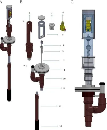
The controller (Figure 1) uses the energy fluctuations inside a tensiometer located in the active root zone of the crop to mechanically enable and cut-off irrigation when the soil-water tension (SWT) reaches a pre-set threshold. Variations in the tension inside the tensiometer are transferred to a hydraulic valve, which in turn operates the irrigation supply valve. As the soil dries, water is drawn from the tensiometer into the soil and a tension (or partial vacuum) is applied to the water inside the tensiometer. Conversely, when the soil is wet, water flows into the tensiometer, thus the tension decreases.
The controller was designed and constructed using readily available hydraulic fittings and other componentry. A rubber diaphragm (1 mm thick and 90 mm in diameter) was installed between two 90 mm diameter plastic flanges mounted onto the top of a tensiometer. The underside of the diaphragm was exposed to the water and/or partial vacuum inside the
tensiometer. A plastic connector was mounted onto the upper surface of the diaphragm and connected to a 4 mm diameter by using an 18-mm length threaded steel bolt (termed the “activation rod”). The activation rod was directly connected to the switch valve using a nut (Figure 1B.6). When the soil dries, the diaphragm pushes down, moving the activation rod and the valve actuation assembly. The valve actuation assembly press the push button of the hydraulic valve thereby activating the irrigation system. The valve actuation assembly (Figure 1B.5), valve mount (Figure 1B.7), and external support shroud (Figure 1B.8) were made from plastic piping. A silicon tap (Figure 1B.9) is used to close the tensiometer and allow for performing maintenance.
The SWT required to actuate the irrigation is regulated by a steel spring (Figure 1B.3) compressed by a nut (Figure 1B.4). Hooke's law (Moyer, 1977) states that the force required to compress a spring is linearly proportional to the distance from its equilibrium length as follows:
A. B. C.
(1) Rubber diaphragm clamped between two plastic flanges, (2) Threaded activation rod, (3) Spring to adjust and/or calibrate the activation soil-water tension, (4) Nut to regulate the spring compression, (5) Valve actuator assembly, (6) Hydraulic valve mechanically actuated, (7) Valve mount, (8) External support shroud, (9) Silicon tap, (10) Connection tee, (11) Visible tube, (12) PVC tube, and (13) Ceramic cup
F= −kx
where:
F - resulting force vector (i.e. the magnitude and direction of the restoring force the spring exerts);
x - displacement vector (i.e. the distance and direction in which the spring is deformed); and,
Figure 1. Irrigation controller actuated mechanically by soil tension. (A) External view, (B) irrigation controller actuated mechanically by soil tension exploded, and (C) internal view mounted
k - force constant of the spring that depends on the spring's material and construction.
Hence, changing the displacement vector of the spring (x) will change the SWT required to activate the irrigation. Preliminary, the testing of springs with different spring constants resulted in the selection of a spring with the following characteristics: external diameter of 10 mm, internal diameter of 7.5 mm, free length of 40 mm, pitch of 3.8 mm, thickness of material of 1.1 mm, and coil number of 11. The spring compression could be adjusted to provide actuation of the controller over a range of SWTs up to approximately 30 kPa.
A commercial pneumatic valve (Univer, model switch 3/2 NO AI9310) activated by a mechanical push button with a threaded mounting bolt was used as the switch valve (Figure 2). The hydraulic supply port on the switch valve receives water from the pressurized irrigation main line through a 4-mm microtube, and the use port is connected to the irrigation supply valve. When the push button is not activated (Figure 1.C), the water passes from the supply port to the use port, closing the irrigation supply valve and stopping irrigation. When the push button is activated by increasing SWT, the switch valve closes the supply line and vents the use line allowing the irrigation supply valve to open, thereby initiating irrigation.
The mechanical performance of six irrigation controllers was evaluated in the laboratory. Since the controllers were hand-made, there were manufacturing imperfections among them, consequently the experiments aimed to evaluate the prototype controllers individually. A water supply at a constant pressure head of 150 kPa was connected to the supply port of the switch valve while the use port was connected to a hydraulic irrigation valve. The tensiometer was sealed and a syringe was used to apply a vacuum to simulate SWT. Pressure transducers (Motorola, MPX5100DP) were used to record the vacuum applied to the tensiometer and the readings were logged every 10 s. Each controller was evaluated four times at the following eight levels of spring adjustment 0, 2, 4, 6, 8, 10, 12 and 14 mm. Pairs of data accounting for spring adjustment and the vacuum required to switch on the irrigation valve were gathered and used for fitting a linear equation corresponding to each controller.
The force required to close the switch valve and initiate irrigation (Finitiate) is a function of four controller components that influence the operation of the switch valve:
where:
FCSCA - force required to overcome the spring compression
at specific levels of adjustment;
FCSD - force required to further compress the spring to mechanically actuate the hydraulic valve;
FMAHV - force required to overcome the displacement required
to activate the hydraulic valve; and,
Fresistance - force required to overcome the resistance of the
rubber diaphragm and the friction associated with movement of the other controller components.
The force required to initiate the irrigation was calculated as:
Figure 2. Mechanically actuated hydraulic valve (1) supply port, (2) use port, (3) exhaust port and (4) push button
initiate CSCA CSD MAHV resistance
F =F +F +F +F
initiate initiate D
F =P ⋅A
where:
Pinitiate - pressure (i.e. soil-water tension in N m
-2) required to
close the switch valve and initiate the irrigation; and, AD - diaphragm area (m2).
FCSCA, FCSD, and FMAHV were obtained by using a universal testing machine to measure the forces associated with compression of the adjustment spring and the switch valve movement. The adjustment springs for each of the six controllers were compressed to a total of 15 mm (40% of deformation) at a speed of 3 mm min-1. The activation pin/spring assembly for the switch valves was also tested and compressed a total of 3 mm at a speed of 1 mm min-1. In both cases, the force was recorded every 0.2 mm of displacement and each spring or valve was tested three times. The displacement required to open the switch valve to water flow was also observed. The total resistance force for each controller assembly was calculated by difference using Eq. 2.
Results and Discussion
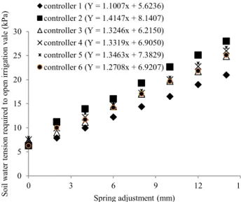
The relationship between the spring adjustment and the SWT required to open the irrigation valve was linear with a gradient ranging from 1.10 to 1.41 kPa mm-1 (Figure 3). The linear
Figure 3. Soil-water tension required to initiate irrigation and the corresponding values of spring adjustment
(2)
(3)
0 5 10 15 20 25 30
0 3 6 9 12 15
Soil
wa
te
rt
en
si
on
re
qu
ired
to
op
en
irrigation
vale (kPa)
Spring adjustment (mm) controller 1 (Y = 1.1007x + 5.6236) controller 2 (Y = 1.4147x + 8.1407) controller 3 (Y = 1.3246x + 6.2150) controller 4 (Y = 1.3319x + 6.9050) controller 5 (Y = 1.3463x + 7.3829) controller 6 (Y = 1.2708x + 6.9207) 4
2
equations corresponding to each controller are also presented in Figure 3 and are useful for defining the spring adjustment and its corresponding value of the SWT for which irrigation must be initiated. The SWT required to initiate irrigation was raised by tightening the spring adjustment. The evaluation of the six hand-made controller prototypes identified variations between the SWT values required to activate the individual controllers. Considering the spring adjustment of 14 mm, the coefficient of variation of the SWT required to initiate irrigation was 9.2% as compared to the controllers.
The magnitude of Cv comes from differences in mechanical parts of the controllers (especially those related to frictional forces), but also from slight heterogeneity of the ceramic cups installed at the tip of the controllers. Irmak & Haman (2001) evaluated five Watermark® granular matrix sensors, which are also SWT-based sensors, in two soils and obtained a CV of sensor resistance of 5.1 and 7.7%.
Cháves et al. (2011) evaluated different soil water sensor in a sandy clay loam soil, and found the Watermark sensor overestimated soil water content by 11.2 ± 12.6%. McCann et al. (1992) obtained a CV value of 11% for 49 Watermark model 200 sensors and reported that using the average reading of a number of sensors rather than the reading from a single sensor may increase the degree of confidence in the measurements. Therefore, the obtained value of CV is similar to results of other SWT based-sensors previously reported.
There are two force components (FCSCA and FCSD) exerted by the adjustment spring. FCSD was small (3.2 ± 0.9 N) and there was no significant difference (p < 0.05) between the six springs used in the controllers. Similarly, FCSD did not change significantly with increasing the compression of the adjustment spring. As expected, FCSCA increased linearly when increasing the compression of the adjustment spring and ranged up to 20.0 N ± 1.5 N at 14 mm of compression. No significant differences were found in FCSCA between the six springs at any level of compression.
Activation of the hydraulic valve requires movement of a spring loaded push button (Figure 2). The full 3 mm stoke movement of the push button required the application of 7.1 ± 0.8 N. However, the push buttons only needed to be moved 2.2 ± 0.3 mm to fully active the switch valves and the FMAHV required was 5.5 ± 0.7 N.
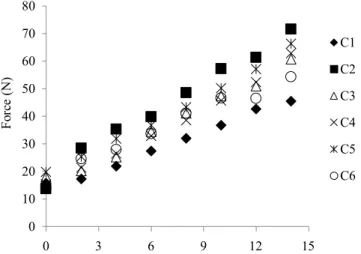
FResistance represents all of the forces (e.g. diaphragm and friction
resistance) that could not be directly measured and was calculated by difference using Eq. 2. FResistance increased with compression of the adjustment spring (Figure 4) and ranged from 17.4 N ± 2.4 N at the spring adjustment of 0 mm to 59.3 N ± 9.0 N at 15 mm. Differences in the calculated FResistance among individual controllers (Figure 4) mirrored the differences observed for the SWT required to initiate irrigation (Figure 3). A comparison of the component forces required to be overcome for controller activation (Figure 5) highlights that the FResistance represents approximately 70% of the total force where the variability among controllers increased when higher SWTs are used to initiate irrigations. However, as the adjustment spring was compressed, FCSCA was found to contribute more than 20% of the total force.
Differences in activation SWT response between individual controllers were largely attributable to differences in the
FResistance most likely associated with construction resistances.
Machine manufacturing of the controllers might improve
0 10 20 30 40 50 60 70 80
0 3 6 9 12 15
Fo
rc
e(
N)
C1
C2
C3
C4
C5
C6
Figure 4. Effect of adjustment spring compression on the calculated resistance force of the controllers
0 10 20 30 40 50 60 70
Fo
rc
e(
N)
FCSCA FCDS
Fresistance FMAHV
0 10 20 30 40 50 60 70 80
7 5. 10 15 20 25
Pr
op
or
tio
na
lo
f to
ta
lf
or
ce
(%
)
Activation soil-water tension (kPa)
A.
B.
Bars indicate standard deviation
Figure 5. Component forces (A), and component force contribution expressed as a proportion of the total force, required to initiate irrigation using the mechanical controller at five levels of soil-water tension (B)
batch consistency and reduce differences in FResistance. However, differences in the activation SWT observed between controllers could also be reduced by individual controller calibration.
et al., 2013). Calibration of the proposed controller could be readily achieved by applying a vacuum to the tensiometer, which is equivalent to the required activation SWT, and twisting the adjustment spring nut until the hydraulic valve is opened.
Conclusion
The irrigation controller developed and presented in this study has been shown to be functional and operated effectively for a range of SWTs up to 30 kPa. Higher values of SWT could be achieved by using springs of appropriate higher spring coefficient. Additionally, accuracy can be improved by performing individual controller calibration.
Acknowledgments
The principal author acknowledges the Foundation for Research Support of São Paulo (FAPESP) for his PhD scholarship, and thanks the National Council for Scientific and Technological Development (CNPq) and the FAPESP for providing a scholarship to undertake this research. CNPq, FAPESP and the Ministry of Science and Technology also provided additional financial support through the National Institute of Science Engineering and Technology in Irrigation (INCTEI).
Literature Cited
Alves, D. G.; Pinto, M. F.; Salvador, C. A.; Almeida, A. C.; Almeida, C. D. de; Botrel, T. A. Modeling for the design of a micro-irrigation system using branched microtubes. Revista Brasileira de Engenharia Agrícola e Ambiental, v.16, p.125-132, 2012. https:// doi.org/10.1590/S1415-43662012000200001
Cardenas-Lailhacar, B.; Dukes, M. D. Precision of soil moisture sensor irrigation controllers under field conditions. Agricultural Water Management, v.97, p.666-672, 2010. https://doi.org/10.1016/j. agwat.2009.12.009
Chávez, J. L.; Varble, J. L.; Andales, A. A. Performance evaluation of selected soil moisture sensors. In: Proceedings of the Central Plains Irrigation Conference. Burlington. 2011. p.29-38.
Dabach, S.; Lazarovitch, N.; Simunek, J.; Shani, U. Numerical investigation of irrigation scheduling based on soil water status. Irrigation Science, v.31, p.27-36, 2013. https://doi.org/10.1007/ s00271-011-0289-x
Dittoh, S.; Akuriba, M. A.; Issaka, B. Y.; Bhattarai, M. Sustainable micro-irrigation systems for poverty alleviation in the Sahel: A case for “micro” public-private partnerships. In: African Association of Agricultural Economists, 3, 2010, Cape Town, South Africa. Proceedings... Cape Town, Agricultural Economics Association of South Africa (AEASA), 2010. CD Rom
Hoppula, K. I.; Salo, T. J. Tensiometer-based irrigation scheduling in perennial strawberry cultivation. Irrigation Science, v.25, p.401-409, 2007. https://doi.org/10.1007/s00271-006-0055-7
IEA - International Energy Agency. World Energy Outlook: Energy systems in emerging economies and developing countries, Paris: OECD/IES, 2011. p.196.
Irmak, S.; Haman, D. Z. Performance of the watermark granular matrix sensor in sandy soils. Applied Eng Agric, v.17, p.787-795, 2001. https://doi.org/10.13031/2013.6848
Karlberg, L.; Rockström, J.; Annandale, J. G.; Steyn, J. M. Low-cost drip irrigation - A suitable technology for southern Africa?: An example with tomatoes using saline irrigation water. Agricultural Water Management, v.89, p.59-70, 2007. https://doi.org/10.1016/j. agwat.2006.12.011
Klein, V. A. Uma proposta de irrigação automática controlada por tensiômetros. Revista Brasileira de Agrociência, v.7, p.231-234, 2001.
McCann, I. R.; Kincaid, D. C.; Wang, D. Operational characteristics of the watermark model 200 soil water potential sensor for irrigation management. Applied Engineering in Agriculture, v.8, p.603-609, 1992. https://doi.org/10.13031/2013.26131
Moyer, A. E. Robert Hooke’s Ambiguous Presentation of “Hooke’s Law”. Isis, v. 68, p. 266-275, 1977. https://doi.org/10.1086/351771 Nolz, R.; Kammerer, G.; Cepuder, P. Calibrating soil potential sensors integrated into a wireless monitoring network. Agricultural Water Management, v.116, p.12-20, 2013. https://doi.org/10.1016/j. agwat.2012.10.002
Pinmanee, S.; Spreer, W.; Spohrer, K.; Ongprasert, S.; Muller, J. Development of a low-cost tensiometer driven irrigation control unit and evaluation of its suitability for irrigation of lychee trees in the uplands of Northern Thailand in a participatory approach. Journal of Horticulture and Forestry, v.3, p.226-230, 2011. Postel, S.; Polak, P.; Gonzales, F.; Keller, J. Drip irrigation for small
farmers. A new initiative to alleviate hunger and poverty. International Water Resources Association, v.26, p.3-13, 2001. Souza, R. D. M.; Miranda, E. P.; Nascimento Neto, J. D.; Ferreira,
T. T. S.; Mesquita, F. P. Irrigação localizada por gravidade em comunidades agrícolas do Ceará. Revista Ciência Agronômica, v.40, p.34-40, 2009.
Souza, R. R. M.; Botrel, T. A. Modelagem para o dimensionamento de microtubos em irrigação localizada. Revista Brasileira de Engenharia Agrícola e Ambiental, v.8, p.16-22, 2004. https://doi. org/10.1590/S1415-43662004000100003