Faculdade de Ciências e Tecnologia
Departamento de Física
Modulation of electrical stimulation applied
to human physiology and clinical diagnostic
Tiago Sérgio Santos Rodrigues Araújo
Thesis submitted in the fulfillment of the requirements for the Degree of Doctor in Biomedical Engineering, under the scientific guidance of Professor Hugo Gamboa.
Copyright cTiago Sérgio Santos Rodrigues Araújo, Faculdade de Ciências e Tecnologia,
Universidade Nova de Lisboa
The course of events for pursuing my PhD degree allowed truly meaningful academic, professional and personal growth. During this learning experience, I had the opportunity to count on exceptional people, who deserve my profound acknowledgment for their active collaboration and constant support. In the following lines I express my gratitude to some people that made all of this possible.
My first acknowledgment words go to my academic supervisor Professor Hugo Gam-boa for his guidance, support and friendship. I also thank him for giving me intellectual freedom in this exploratory process and inspiration to move forward. Thank you for showing me the path for rigor, clarity, motivation and, above all, the ability to question. These last years under your guidance gave me tools, virtues and capabilities that I will use for the rest of my life.
My second word of acknowledgment goes to Professor Alberto Cliquet, my internship coordinator at UNICAMP - Brasil. Thank you for being kind enough to welcome me with open arms and also provide the most intense research experience that I had. Thank you for the wisdom, the friendship and the sense of contribution that you always passed me. Working with the patients fromLaboratório de Marcha e Reabilitação do Aparelho Locomotor, Hospital de Clinicas, UNICAMP, was the most enriching process of this PhD. Although
thinking that I would transmit strength and motivation to highly disabled people, it was them who gave me all the motivation and strength to follow my way. To all of them a big thank you. I also thank my co-workers from the rehabilitation wing, namely Karina, Elize (she was tireless with me!), Carolina, Janaina and Paola.
I thank Professor Pedro Costa from FCM-UNL with whom I spent several work hours and had long discussions that gave me solid bases on human electrophysiology, supporting this work. I equally thank Professor Ana Fred from IST and Professor Paulo Armada from FMH, with whom I developed two important curricular components of this PhD.
A thank you to Professor Pedro Mil-Homens, from FMH, for the prompt availability of a laboratory and the Biodex system, without which the study described in Chapter 7 would not be possible, and for the external accompaniment to my doctoral course. I also equally thank Professor Mamede de Carvalho, FML-UL, who promoted and followed the study depicted in Chapter 6 of this document and the validation study of the electrical stimulator device.
complishment of this project: Fundação para a Ciência e Tecnologia, PLUX - Wireless Biosignals, S.A. and FCT-UNL- CEFITEC.
I thank Plux - Wireless Biosignals, S.A., the company that welcomed me during most of my PhD, that fully funded the technical developments necessary and that provided me a deep professional enrichment in varied areas. Plux is the people that work there and because of that I thank all collaborators in general with relevance to those who actively helped me in the developments. To Filipe Silva, working with him is a unique experience because of his technological knowledge and logic reasoning well above average. I will always look to each and every teaching and time-sharing moment with fascination. When no one else knows how to solve it, he will! I also thank Fernando Cardoso and Filipe Carvalho who accompanied my hardware developments. A special thanks to Paulo Aires and Dário Bento, great friends, and that besides all the technical support knew how to rejoice every day, every hour. And what is life without joy?
Thanks also to my friends, Nuno Santos, Nídia Batista, Madalena Serra, Carina Morais, Ana Raquel and David Pires for the excellent inputs they gave to this thesis.
To all my master students that I had the pleasure to coordinate and also my students from Applied Electronics. I taught to learn and learned from teaching.
To my dear friends: Rogério Rocha, Eliana Rocha for their constant presence, care, help, assertiveness and motivation and for the "two little things" that they put in this world that I love from the deep of my heart, Gonçalo and Martim, for all the fun, hugs and affection. To Padre Jorge for the spiritual purity that you provide me. To Carlos Amorim and Daniele Pereira, Daniel Garrudo, João Fonseca, Luís Galvão, Pedro Benvindo, João Mendes, you are family to me =).
To my Mom and Dad for their unconditional love. The good things that I do in my life is with you and for you. I love you more than anything. To them and to my godson Martim I dedicate this work.
The use, manipulation and application of electrical currents, as a controlled interfer-ence mechanism in the human body system, is currently a strong source of motivation to researchers in areas such as clinical, sports, neuroscience, amongst others. In electrical stimulation (ES), the current applied to tissue is traditionally controlled concerning stimu-lation amplitude, frequency and pulse-width. The main drawbacks of the transcutaneous ES are the rapid fatigue induction and the high discomfort induced by the non-selective activation of nervous fibers.
There are, however, electrophysiological parameters whose response, like the response to different stimulation waveforms, polarity or a personalized charge control, is still unknown. The study of the following questions is of great importance:
• What is the physiological effect of the electric pulse parametrization concerning
charge, waveform and polarity? Does the effect change with the clinical condition of the subjects?
• The parametrization influence on muscle recruitment can retard fatigue onset?
• Can parametrization enable fiber selectivity, optimizing the motor fibers recruitment
rather than the nervous fibers, reducing contraction discomfort?
Current hardware solutions lack flexibility at the level of stimulation control and physiological response assessment. To answer these questions, a miniaturized, portable and wireless controlled device with ES functions and full integration with a generic biosignals acquisition platform has been created. Hardware was also developed to provide complete freedom for controlling the applied current with respect to the waveform, polarity, frequency, amplitude, pulse-width and duration.
The impact of the methodologies developed is successfully applied and evaluated in the contexts of fundamental electrophysiology, psycho-motor rehabilitation and neuro-muscular disorders diagnosis.
O uso, manipulação e aplicação de correntes eléctricas no corpo humano como um mecanismo de interferência controlado motiva, actualmente, um grande número de in-vestigadores do contexto clínico, desportivo, das neurociências, entre muitos outros. A corrente aplicada no tecido é tradicionalmente controlada ao nível da frequência, ampli-tude e largura de pulso. Os maiores inconvenientes da estimulação eléctrica transcutânea residem numa rápida indução de fadiga muscular e elevada activação de fibras de dor.
Existem, no entanto, parâmetros cuja resposta electrofisiológica é pouco abordada, como a forma de onda do estímulo eléctrico, a polaridade e a carga total do impulso, tornando-se relevante o levantamento das seguintes questões:
• Qual o efeito fisiológico da parameterização do estímulo eléctrico ao nível da forma
de onda, carga e polaridade? Esse efeito difere com a condição clínica do sujeito?
• A influência que a parameterização do estímulo eléctrico provoca no recrutamento
muscular pode retardar o efeito de fadiga?
• Poderá a parameterização possibilitar uma selectividade das fibras activadas,
op-timizando o recrutamento das fibras motoras e consequentemente reduzindo o disconforto de contracção?
As soluções de hardware disponíveis actualmente para estimulação eléctrica são pouco flexíveis e deficitárias no âmbito da investigação. Para dar resposta a estas questões, foi desenvolvido um dispositivo miniaturizado, portátil e wireless com funções de electro-estimulação e de sincronização com dispositivo genérico de aquisição de biossinais. O hardware foi desenvolvido visando a total liberdade no controlo da corrente aplicada tendo em consideração a forma de onda, polaridade, frequência, amplitude, largura de pulso e duração.
O impacto das soluções desenvolvidas foi avaliado no contexto da electrofisiologia geral e em contexto clínico, especificamente, na reabilitação psicomotora e no diagnóstico de patologias neuromusculares.
Contents xv
List of Figures xix
List of Tables xxiii
1 Motivation 1
1.1 State-of-the-Art . . . 1
1.2 Questions and Goals . . . 4
1.3 Thesis Structure . . . 6
2 Background 9 2.1 Electrophysiology Principles . . . 9
2.1.1 Resting potential . . . 9
2.1.2 Action potential . . . 10
2.1.3 The nerve cell as a conductor . . . 11
2.2 Electrical Stimulation Principles . . . 12
2.2.1 Historical context . . . 14
2.2.2 Excitability . . . 15
2.2.3 Stimulation parameters and physiological impact . . . 16
2.3 Application of current . . . 21
2.3.1 Current Types . . . 21
2.3.2 Transcutaneous stimulation electrodes . . . 22
2.3.3 Electrode Placement . . . 22
2.4 Electrical Stimulation Circuits . . . 23
2.4.1 Micro-controller . . . 24
2.4.2 High Voltage . . . 24
2.4.3 Regulation Mode . . . 25
2.4.4 Stimulation Steering . . . 26
3 Proposed Solution 29 3.1 Requirements . . . 29
3.1.1 Functional and Technical Requirements . . . 29
3.1.3 Safety Requirements . . . 32
3.1.4 Software Requirements . . . 32
3.2 Hardware . . . 33
3.2.1 Microcontroller . . . 34
3.2.2 Power . . . 41
3.2.3 High Voltage . . . 43
3.2.4 User interface . . . 44
3.2.5 Current drive . . . 44
3.2.6 Digital port . . . 46
3.2.7 Application interface . . . 47
3.3 Electrical stimulator device . . . 48
3.3.1 Printed Circuit Board . . . 49
3.3.2 Box Enclosure . . . 49
3.3.3 The Product . . . 50
3.4 Software . . . 51
3.4.1 API . . . 52
3.4.2 Interfaces . . . 54
4 Validation 57 4.1 Device Tests . . . 57
4.1.1 Characterization Tests . . . 57
4.1.2 Production Tests . . . 60
4.2 Scientific Validation . . . 61
4.2.1 Nerve Regeneration on Rat . . . 61
4.2.2 Instrumentation . . . 62
4.2.3 Control Interface . . . 63
4.2.4 Protocol . . . 63
4.2.5 Outcomes . . . 65
4.2.6 Real-time stimulation impact on the ANS . . . 66
5 Application to Neuroplasticity of Tetraplegic Subjects 73 5.1 Introduction . . . 73
5.2 Methods . . . 74
5.2.1 Subjects . . . 74
5.2.2 Procedure . . . 75
5.2.3 Data analysis . . . 76
5.3 Results . . . 77
5.4 Discussion . . . 81
6 Application to the Waveform Control on CMAP Scan 85 6.1 Introduction . . . 85
6.2.1 Subjects . . . 87
6.2.2 Instrumentation . . . 87
6.2.3 Stimulation and acquisition . . . 87
6.2.4 Processing . . . 89
6.3 Results and Discussion . . . 89
7 Application to the Waveform Effect on Fatigue and Comfort 95 7.1 Introduction . . . 95
7.2 Methods . . . 96
7.2.1 Subjects . . . 96
7.2.2 Instrumentation . . . 96
7.2.3 Protocol . . . 98
7.2.4 Data analysis . . . 101
7.3 Results . . . 102
7.4 Discussion . . . 103
8 Conclusions 105 8.1 Overall Results . . . 105
8.2 Contributions . . . 108
8.3 Future Work . . . 111
A List of Publications 113 A.1 Book Chapters . . . 113
A.2 Journal Papers . . . 113
A.3 Conference Proceedings . . . 114
A.4 Oral Communications . . . 115
B Tools 117 B.1 Stimulator Development . . . 117
B.2 Scientific Computation . . . 117
B.3 Thesis Document . . . 118
C Brochure 119
D Test Protocol 121
E Classification of Spinal Cord Injury 127
1.1 Illustration of the rehabilitation process through the reeducation of nerve fibers. 2 1.2 Illustration of the scientific and methodological alignment of this work. The
scientific questions, the methodological solution and the studies implemented
envisioning the answer of those questions. . . 5
1.3 Thesis structure. . . 6
2.1 Membrane potential and respective polarity. . . 10
2.2 Representation of an action potential and excitability threshold. . . 11
2.3 Diffusion of sodium and potassium . . . 11
2.4 Propagation of the potential and conditioning factors at a fixed time instant. . 13
2.5 Electric model of the cellular membrane by Hodgkin and Huxley. . . 14
2.6 The strength-duration curve for current, energy and charge of an excitable tissue. . . 16
2.7 Amplitude and period of a wave. . . 17
2.8 Strength-Duration curves: Relation between amplitude and pulse-width when relating with the influence on excitability thresholds. . . 18
2.9 Relation between the pulse-width applied and the accommodation of the nervous fiber. . . 18
2.10 Muscular strength variation with the stimulus frequency, for stimulation inten-sities above the motor limit. . . 19
2.11 Examples of electric pulses with different polarities and waveforms. . . 20
2.12 Comparison of stimulation waveforms for their ability to generate low thresh-old stimulation, low corrosion, and low tissue damage. . . 20
2.13 Electrodes configuration. . . 23
2.14 Generic configuration of the state of the art stimulators. The Regulation Mode and Stimulation Steering blocks define the Output Stage of the electrical stimu-lator. . . 24
2.15 Step-up converter or Boost converter. . . 25
2.16 Output stage for a constant current stimulator with a voltage controllable current source. . . 26
2.18 Representation of a typical current steering output stage. . . 28
3.1 Overview of the hardware architecture. . . 33
3.2 Overview of the modules for the whole system and correspondent data flow inputs/outputs for the microcontroller. . . 34
3.3 The three main memory types and its structure on the device. . . 35
3.4 Structure of the application code. . . 37
3.5 Illustration of the UART interrupts divided into received or sent commands. . 39
3.6 Illustration of the power module architecture. . . 42
3.7 Illustration of the high voltage module architecture. . . 43
3.8 Device button turned off and with green and red LED turned on. . . 44
3.9 Illustration of the current drive module architecture. . . 45
3.10 Representation scheme of the acquisition and stimulation system, with syn-chronization cable. . . 47
3.11 Illustration of the development cycle of the final solution, composed by three main development classes: hardware design, implementation and miniaturiza-tion on PCB and final box enclosure. . . 48
3.12 Illustration of the PCB version v1.1. . . 49
3.13 Box assembly illustration of the stimulator . . . 50
3.14 Accessories for a) nerve stimulation; b) muscle stimulation. . . 50
3.15 Photograph of the final electrical stimulation device and summary of specifica-tions. . . 51
3.16 Integrated API for biosignals acquisition and control of the stimulator. . . 52
3.17 Illustration of the system communication and control flexibility. . . 54
3.18 Diagram representing the standard communication flow (from configure to control) . . . 55
3.19 Examples of waves that can be drawn and stored in the device. . . 56
4.1 Example of a test point in the device’s PCB. The TP circles represent the Test Points of the circuit. . . 61
4.2 Illustration of the system used to induce muscle contraction and respective force assessment. . . 62
4.3 Apparatus for force assessment: a) servomotor; b) pedal; c) load cell; d) rotation axis; e) optical encoder; f) rat paw attached to pedal; g) invasive electrical stimulation electrode; h) thermal pad. . . 63
4.4 First layout interface used for real time calibrations and thresholds definition, before application of protocol: a) Computer based layout; b) Android based layout. . . 64
4.5 Variation of force with stimulation frequency. . . 65
4.6 Variation of force with ankle angle. . . 66
4.8 Example of an EDA event and possible extracted parameters. . . 68 4.9 EDA signals obtained for all subjects. . . 69 4.10 Example of the BVP signal from one subject during the segment 2 of the
acquisition protocol . . . 70
5.1 Illustration of Test 1 and Test 2 stimulation electrodes positioning and respec-tive evaluated muscles through EMG acquisition . . . 75 5.2 Illustrative schematics for the stimulation and acquisition protocol. . . 76 5.3 Reflexes mean peak-to-peak amplitude inµV (with SD error bars) related to
the stimulation intensity for Test 1 and three groups. . . 78 5.4 Results of ILR elicited with different stimulation intensities for Test 1 in: a)
healthy subjects (example from one subject of Control Group); b) SCI subjects (representative example from one subject of Group 1). . . 79 5.5 Mean values (and SD error bars) for the reflexes latency related to the
stimula-tion charge for: a) Test 1 and b) Test 2. The stimulastimula-tion charge is complemented by the indication of the mode and intensity of the original electrical pulse. . . 80 5.6 Results of EMG response with different stimulation intensities of the Test 2
from the unique patient that exposed a different rise pattern of ILR latency related to the stimulation charge. . . 83
6.1 Representations of CMAP scans. A) From an healthy individual. B) From an ALS patient. . . 86 6.2 Illustration of the equipment used and electrodes placement . . . 87 6.3 Illustrative schematics for the stimulation and acquisition protocol. . . 88 6.4 Example of the charge equalization of the four different pulse waveforms.
Main-taining the amplitude and the area of the pulse, the only variable parameter is the pulse-width, to equalize the charge. . . 89 6.5 CMAPs acquired in a fixed intensity step for each waveform: 10.5mA.
Differ-ences in the waves’ amplitude, with the same intensity stimulation, can be observed. . . 91 6.6 Four CMAP scans generated with four waveforms, for one example subject. . 91
7.1 Subject prepared to be evaluated by the Biodex system and electrical stimulator. Two electrodes are positioned over vastus medialis and on the lateral border of the femoral rectus. The stimulated limb is maintained in isometric conditions. 97 7.2 Illustrative schematics for the MVIC test acquisition protocol. . . 99 7.3 Illustrative schematics of the acquisition and stimulation protocol defined to
determine the amplitude required to elicit 50% of MVIC. . . 99 7.4 Illustrative schematics of the acquisition and stimulation fatigue protocol. . . 100 7.5 Example of the declining torque of a subject during fatigue test with SQ shape
7.6 Decline in percentage of the MVIC over repeated contractions for QU, SQ and TR (mean (SD)). No significant differences between QU, SQ and TR (P > 0.05). 103
3.1 Functional requirements and the correspondent technical requirements. . . . 31 3.2 The LEDs indication and correspondent device state. . . 41
4.1 Description, initial condition and expected results of the communication tests. 58 4.2 Description, initial condition and expected results of the battery and charge
management tests. . . 59 4.3 Description, initial condition and expected results of the current
parametriza-tion tests. . . 60 4.4 Mean values and respective standard deviation error for the heart rate (in beats
per minute) obtained during segments 1, 2 and 3. . . 71
5.1 Number of subjects per group that elicited significant reflexes in the three stimulation modes versus the total number of subjects analyzed. . . 77 5.2 Linear tendency equations and correspondentR2of latency vs charge for all
groups and tests. . . 78
6.1 S95 response amplitudes. SQ corresponds to the monophasic square pulse, TR to monophasic triangular pulse, QU to monophasic quadratic pulse and BSQ to the biphasic square pulse. . . 90 6.2 Mean CMAP scan slope differences between the different types of waveforms.
SQ corresponds to the monophasic square pulse, TR to monophasic triangular pulse, QU to monophasic quadratic pulse and BSQ to the biphasic square pulse. 92 6.3 S5 current intensities. SQ corresponds to the monophasic square pulse, TR to
monophasic triangular pulse, QU to monophasic quadratic pulse and BSQ to the biphasic square pulse. . . 92 6.4 Current intensity differences for each waveform relative to the square wave.
SQ corresponds to the monophasic square pulse, TR to monophasic triangular pulse, QU to monophasic quadratic pulse and BSQ to the biphasic square pulse. 93
7.1 Summary of stimulation characteristics for 3 waveforms. SQ - Square waveform; TR - Triangular waveform; QU - Quadratic waveform. . . 97 7.2 Demographic variables (Sex, Age, Body Mass Index (BMI), Dominant leg,
7.3 Mean (SD) amplitude and charge values obtained for all subjects. . . 102 7.4 Pairwise comparisons amongst waveforms, relative comfort scores. F: Value of
ANOVA Friedman test. *Significantly differentp < 0.05 . . . 103
AC Alternating Current.
ACK Acknowledge.
ADC Analog-to-Digital Converter.
AES Advanced Encryption Standard.
ALS Amyotrophic Lateral Sclerosis.
ANS Autonomic Nervous System.
AP Action Potential.
API Application Programming Interface.
ASIA American Spinal Injury Association.
BMI Body Mass Index.
BVP Blood Volume Pulse.
CMAP Compound Muscle Action Potential.
CPU Central Processing Unit.
CRC Cyclic Redundancy Check.
CRNN Continuous Running if No Network.
DAC Digital-to-Analog Converter.
DC Direct Current.
ECG Electrocardiography.
EDA Electrodermal Activity.
EDR Enhanced Data Rate.
EEPROM Electrically-Erasable Programmable Read-Only Memory.
EMG Electromyography.
FES Functional Electrical Stimulation.
GPIO General Purpose Input Output.
GUI Graphical User Interface.
HCI Human Computer Interface.
HR Heart Rate.
HRV Heart Rate Variability.
HV High Voltage.
I2C Inter-Integrated Circuit.
IDE Integrated Development Environment.
ILR Interlimb Reflexes.
JSON JavaScript Object Notation.
LDO Low-dropout Regulator.
LED Light Emitting Diode.
MAC Media Access Control.
MU Motor Unit.
MUAP Motor Unit Action Potential.
MVIC Maximum Voluntary Isometric Contraction.
NMES Neuromuscular Electrical Stimulation.
NOK Not Ok.
NS Next State.
op-amp operational amplifier.
PCB Printed Circuit Board.
PMA Progressive Muscular Atrophy.
PWM Pulse Width Modulation.
SCI Spinal Cord Injury.
SDK Software Development Kit.
TTL Transistor-Transistor Logic.
UART Universal Asynchronous Receiver/Transmitter.
C
H
A
P
T
1
M
OTIVATION
The human organism can be defined as a system composed by several subsystems: for example the digestive, circulatory, sensory-motor and respiratory systems. Its opera-tion occurs through complex compensaopera-tion mechanisms managed by the nervous and endocrine system. The actions, transmissions and management of the nervous system pass through, amongst other mechanisms, a communication protocol based on electri-cal signals. Biosignals such as Electrocardiography (ECG), Electromyography (EMG), Electroencephalography (EEG) and Electrodermal Activity (EDA) represent functional examples of that inter-systematic communication and management. The application of electric currents to the human body as a tool to interfere with this managing system is currently a field of interest and motivation to worldwide investigators.
1.1
State-of-the-Art
Lack of neural innervation due to neurological damage leads to muscles unable to produce force. Investigators have tried to find a way to restore movement and the ability to perform everyday activities using electrical stimulation.
Whether used alone to improve motor impairment or embedded within complex systems to create functional multi-joint movement, electrical stimulation holds great potential in rehabilitation. Figure 1.1 presents an example of an illustrative rehabilitation process with electrical stimulation through the reeducation of nerve fibers.
Figure 1.1: Illustration of the rehabilitation process through the reeducation of nerve fibers. Courtesy of Parastep [138].
• Healthcare
In the healthcare context, electrical stimulation is usually associated with: the di-agnosis of neuromuscular pathologies (ex: Amyotrophic Lateral Sclerosis (ALS), Progressive Muscular Atrophy (PMA)) [183]; in therapy for wound healing and localized inflammation; treatment of localized neuropathic pain, such as rheumatoid arthritis and lower back pain; to delay the process of inflammation such as tendinitis; and treatment of urinary incontinence and diaphragmatic dysfunction [196]. It can also be used to improve circulation, to increase range of motion and to treat several conditions from sprains, back pain, arthritis, sciatica and scoliosis. Still on the clinical context, it has an important role on the rehabilitation and evaluation of Spinal Cord Injury (SCI) patients. In this field, electric currents are used not only to re-establish functionality or as an assistive method (neuroprotheses), but also as a methodol-ogy for muscle spasm relief or clinical condition evaluation [70]. Imaging studies, such as computerized tomography and nuclear magnetic resonance imaging, do not correlate directly to the clinical status of subjects and lack functional information regarding the sometimes subtle recovery of the patients. On the other hand, method-ologies that involve somehow the applications of currents in the human tissue and access directly the subject’s electrophysiology (Compound Muscle Action Potential (CMAP) scan, Interlimb Reflexes (ILR), EMG), can give detailed information about the clinical condition of the patient [2].
• Research:
• Fitness and sports:
In this field, the capabilities of strengthening and toning muscles are explored in the context of passive gymnastics [104] [17]. The market offers a wide range of stimulation devices to increase muscle strength, decrease body weight and body fat and to improve muscle firmness and tone [148]. From the literature evaluated, this field has the higher coverage in terms of population but commonly unsupervised by qualified personnel.
In all contexts, electrical currents are applied to the excitable tissue with different stim-ulus parametrizations. The parametrization traditionally concerns the pulse frequency, amplitude and duration, however, there are also a set of parameters not frequently ad-dressed, such as pulse charge, waveform and polarity.
There are also some known drawbacks to the use of electric currents in the human body. During electrical stimulation, skeletal muscles fatigue more rapidly using repetitive stimulation than with voluntary contractions [153][187]. Muscle fatigue is defined as a reduction in the peak force, with continuous and repeated activation [130]. Rapid fatigue during Neuromuscular Electrical Stimulation (NMES) is thought to result from the differences in motor unit recruitment order, higher activation frequencies and imprecise control of muscle force compared to voluntary contractions [140]. The problem of muscle fatigue is aggravated by the fact that paralyzed muscle shows greater propensity to fatigue than healthy muscle. Consequently, muscle fatigue is an important factor limiting the clinical use of NMES [25].
Another drawback of this technique is related with the user’s comfort. Pulsed currents become rapidly uncomfortable to the patient [177] [163]. This discomfort is provoked primarily by the activation of the nervous fibersA−δ1, given that artificial electric pulses have low fiber selectivity.
Electrical stimulation may induce a perturbation on the natural human physiology. In terms of the skin, it can easily lead to irritation or burns [177]. High levels of total electric charge can be neurotoxic [122][194][27] and cause nerve damage [126]. This assumes higher proportions given that, with the massification of the methodology, unqualified individuals can themselves easily apply voltages up to 120V. Regarding other physiological changes, very few studies address the impact of electrical stimulation on the Autonomic Nervous System (ANS) [90].
Some authors already tried to address and overcome these stimulation drawbacks. Studies in theoretical models reached to promising conclusions about the decrease of the electrical impulse total charge, optimizing the pulse waveform, as a measure to reduce the fatigue induction [84][85][86], to reduce the risk of burns and skin irritation [19] and to increase the comfort for the patient through nervous fibers selectivity [189][158]. However, practical implementations of those theoretical studies find some methodological barriers,
1A−δfibers, are a type of sensory fibers. They respond to stimuli such as cold and pressure and, the
when manipulating unusual parameters such as the pulse waveform, polarity and charge. Bennie et al. [19] was forced to use two different stimulators to apply different pulse waveforms and a complex set of instruments to acquire several physiological aspects. The authors addressed the problem of stimulus comfort, unfortunately, without any guarantee of time synchronization between the biosignals and the electrical impulses, which compromises the cause-effect analysis.
Even when studying the correlation of the standard parameters, pulse-width [99][67], frequency [57][92][179][96] and amplitude [182][93][83] with its implication on fatigue, complex apparatus need to be implemented at hardware and software level, negatively impacting upon the costs, the development time and the reliability of the results.
When addressing the recent electrical stimulation technology, it is imperative to clarify an important aspect: The market offers a wide variety of solutions with characteristics such as reduced size, portability, high usability and commercial appeal. Mostly, those solutions are completely focused on a solo objective and therefore, the parametrizations of the devices are pre-programmed. As an example we have the vast range of electrical stimulation devices used only for NMES. Details of the current systems and discussion about the main circuit topologies will be given in the next chapter.
However, electrical stimulation has a much wider scope and, mainly in the research context, the degrees of freedom that the current electrical stimulation devices allow are still very insufficient. Even the more robust stimulation systems that allow greater control of the parametrization are limited to the standard parameters such as frequency, amplitude and pulse width, and most of them have limitations on usability, dimensions, complexity, setup time and creation of control routines.
In practice, the main drawbacks of the methodology are still the same as before, and few people investigate, implement or develop turn-key solutions. This fact motivates the development of new hardware configurations, enabling custom parametrizations in the control of current or voltage output.
1.2
Questions and Goals
Concerning the state-of-the-art and the problems previously raised, the following ques-tions become of significant scientific relevance:
• What is the physiological effect of the electric pulse parametrization concerning
charge, waveform and polarity? Does the effect change with the clinical condition of the subject?
• Can parametrization enable fiber selectivity, optimizing the motor fibers recruitment
rather than the nervous fibers, reducing contraction discomfort?
To address these questions, the following methodological developments are required:
1. Develop a new solution for electrical stimulation, that allows:
• Parametrization:Freedom in the electrical pulse control, specifically for stan-dard parameters such as amplitude, frequency and pulse-width, but also wave-form, charge and polarity;
• Synchronization:A cause-effect stimulusversusphysiological response reliable
analysis, concerning temporal synchronization and improved signal quality;
• Usability:The solution should have high usability, reflected in a low intrusive-ness in clinical and laboratory contexts;
• Configurability:The system should have implementation flexibility for
proto-typing, configuration and storage of electrical stimulation protocols.
2. With the solution developed, the following studies addressing human electrophysi-ology are proposed:
• Compare the electrophysiological response of healthy individuals and spinal
cord injury patients, controlling pulse waveform and charge parametrization;
• Study the effects of pulse parametrization in current diagnosis mechanisms of
neurodegenerative pathologies;
• Evaluate the induction of fatigue and comfort using different pulse waveforms
in the context of NMES;
By fulfilling these goals, a solution is developed to mitigate the current drawbacks of electrical stimulation, furthermore enabling new approaches to address fundamental human electrophysiology, as expressed on Figure 1.2.
1.3
Thesis Structure
This thesis summarizes the work developed during the PhD period and divides it into eight chapters and five appendixes. A brief description of the contents of each chapter is described next and Figure 1.3 schematizes its organization.
Figure 1.3: Thesis structure.
• Chapter 1 -Introduction- The present chapter introduces the relevant questions to be answered in this thesis, providing some insight on the motivation and outlining the main goals of this work. This chapter also describes the thesis structure.
• Chapter 3 -Proposed Solution- Focuses on the development of the electrical stimu-lator designed to solve the problem foreseen before. This chapter presents the core of the thesis and covers hardware design, firmware development and software im-plementation. This chapter also introduces the methodologies applied in the context of this thesis.
• Chapter 4 -Validation- This chapter presents the characterization and production tests performed with the device to guarantee that the predefined requirements were fulfilled. Two examples of scientific validation studies performed to enrich the development stage are also described in this chapter.
• Chapter 5 -Application to Neuroplasticity of Tetraplegic Subjects- The scientific questions raised are addressed in three scientific studies (Chapter 5, 6 and 7). In this Chapter, a study comparing the interlimb reflexes of tetraplegic patients and healthy subjects is presented. A correlation between electrical current parametrization and reflexes parameters is addressed.
• Chapter 6 -Application to the Waveform Control on CMAP Scan - The second study analyzes the effect of electrical pulse parametrization in a current diagnose mechanism of neurodegenerative pathologies, the compound muscle action potential scan. This study analyzes how electrical pulses with different waveforms influence the stimulus-response curve given by the CMAP scan.
• Chapter 7 -Application to the Waveform Effect on Fatigue and Comfort- Finally, this Chapter presents the last study which evaluates the impact of electrical pulse parametrization in a neuromuscular electrostimulation protocol. A protocol specifi-cally created to induce fatigue was applied with different electrical pulse waveforms and differences in comfort and fatigue rate were assessed.
• Chapter 8 -Conclusions- This last chapter presents the conclusions of the work, with a critical discussion of the addressed problems, its contributions and extended implications.
• Appendix A- The first appendix provides a list of the author’s publications, book chapters, papers in journals accepted and in review, conference proceedings and oral communications.
• Appendix B- Provides an overview of the tools used for the conducted research.
• Appendix C- A brochure presenting the technical summary of the final stimulator
device.
• Appendix D- Presents the test protocol template defined during validation phase
C
H
A
P
T
2
B
ACKGROUND
The objective of this chapter is to cover the elementary concepts needed for the theoretical support of this thesis. The electrical properties of the cell are explored in Electrophysiol-ogy Principles section. Then, the theoretical concepts on electrical stimulation used for rehabilitation and functional purposes are depicted. Electrical stimulators are analyzed from the historical point-of-view to the current context and the various parameters of electrical stimulation are discussed, including frequency, pulse width, waveform and how they affect human physiology. This chapter goes further within the technical concepts of the electrical stimulators, covering the contemporary circuit topologies in use.
2.1
Electrophysiology Principles
The application of electrical currents in biological tissues is based on deep knowledge of the electrophysiology properties of those tissues. In this section the fundamental concepts on electrical properties of the cell are reviewed.
2.1.1 Resting potential
When the cell is at rest it has a relatively static membrane potential, maintained as long as nothing disturbs it. The resting potential characterizes the difference between the interior (cytoplasm) and the exterior of the cell when it is at rest (Figure 2.1). This electrical potential difference depends on the ionic concentration gradients, which can be altered through the membrane permeability to each ionic species.
Figure 2.1: Membrane potential and respective polarity.
interior of the cell. The equilibrium potential for each ionic species can be mathematically represented by the Nernst equation1. The resting potential varies between -60 and -90 millivolts (mV) depending on the cell type - for instance, in nerves and smooth muscle fibers the resting potential is -70 mV [30]. Any change in the membrane permeability in one of these ionic species will displace the resting potential and may generate an electrical signal, called action potential.
2.1.2 Action potential
In the human body, the basic cell-to-cell communication mechanism over the nervous structures occurs through the Action Potential (AP). The action potential is a wave of electrochemical potential that moves through the membrane. It reverts the membrane potential from -70 mV to +30 mV in less than 1 millisecond (ms). In muscle cells, for example, an action potential is the first step in the chain of events leading to contraction. The electrical impulse is initiated by the membrane’s depolarization due to the chemical disturbance of a synapse, a receptor, or another disturbance like an external electrical impulse. The action potential only starts if the membrane is depolarized in approximately 10 or 15 mV, so around -55 mV as it is observed on Figure 2.2.
The potential value that needs to be surpassed to trigger the action potential is called excitability threshold. When an action potential is triggered physiologically, it will only follow one direction (distal if the nerve is efferent and proximal if afferent). If, however, the action potential is triggered by an artificial electrical impulse in the middle of a nervous fiber, two impulses are generated that will move in opposite directions from the stimulus point.
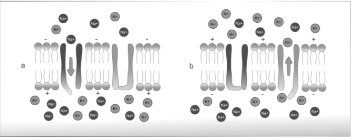
The depolarization above the excitability threshold induces the opening (activation) of the sodium channels, as shown in Figure 2.3 a). When these channels open, there is a current of sodium favoring its concentration gradient and causing a rapid reversion in the
1Nernst equation:V= RT
Figure 2.2: Representation of an action potential and excitability threshold.
membrane’s polarity, from -70mV to 30mV. This depolarization causes an alteration in the electrochemical gradient of the potassium ions, relative to the resting point, therefore acti-vating the potassium channels and generating a potassium current opposite to the sodium current (Figure 2.3 b)) [78]. Simultaneously to this increase of potassium diffusion, occurs the inactivation of sodium channels - this phase is called repolarization. Consequently, there is a decrease in the intra-cellular potential compared to the extra-cellular potential. The additional potassium channels stay open even when the membrane potential reaches the resting level. So, the potential becomes even more negative than when at rest - this phase is called hyperpolarization [18]. Eventually, the extra potassium channels close and the membrane potential goes back to its resting, ’polarized’ level (Figure 2.2).
Figure 2.3: Diffusion of sodium and potassium; a) activation of sodium channels, b) potassium reposition.
2.1.3 The nerve cell as a conductor
the membrane generates an action potential it instantly depolarizes adjacent regions and propagates the impulse.
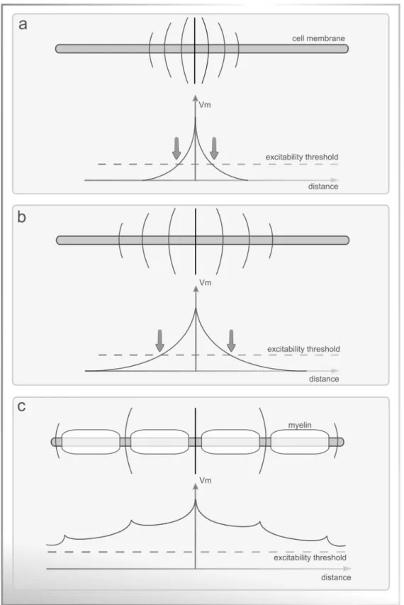
There are three main pathways for the current to flow along the length of the axon: i) An external conductor (extra-cellular fluid) with very low impedance; ii) an internal conductor (axoplasm), with similar impedance from one cell to another due to the uniform ionic composition of the intracellular fluid; and iii) the cell membrane that separates the two conductors. The membrane has an intrinsic capacity and impedance that varies according to each ionic species’ permeability, as it is described in the model of Figure 2.5. As current spreads along the nerve fiber pathways, it is attenuated with distance and a spacial decay constant can be defined, like observed in Figure 2.4 a). If that constant is altered by some mechanism, natural or induced, there is a direct change in the propagation speed of the action potential. Figure 2.4 b) exemplifies a constant of lower decay and therefore a higher conduction speed [101].
The propagation speed of the nervous impulse varies with the nervous fiber’s dimen-sions, geometry and membrane characteristics. In normal situations, as larger the fiber diameter is, faster is the conduction. The action potential propagates along the nerve with a velocity of about 30-120m/s, depending on the nerve type, and reaches the axon terminal where the neurotransmitter acetylcholine is released. There are also cases in which the nervous fibers are enveloped by myelin sheaths (electrically insulating), and interrupted with Ranvier nodules (areas without myelin). The electric potential of the nervous impulse travels along the fiber, but the depolarization occurs only in the Ranvier nodules. When a nodule is depolarized, it triggers the depolarization of the next nodule without generating action potentials in the myelin zones. When this happens, the membrane potential changes in about 100mV, which is sufficient to trigger the action potential in the adjacent nodule. So, the nervous impulse can be described as jumping from nodule to nodule (Figure 2.4 c) ), using less energy but with higher conduction speed. This speedy conduction is called saltatory conduction. The higher is the conduction speed, larger is the extension of the fiber depolarized in each instant [89].
2.2
Electrical Stimulation Principles
2.2.1 Historical context
First records of electrical currents application in therapeutic contexts date from the eigh-teenth century. In 1791 Luigi Galvani initiated the publications of electric current effect in human muscle [142]. In 1831, Michael Faraday showed that electrical currents could stimulate nerves to create active movement [39]. Concerning the therapeutic effects of electrical nerve stimulation, Duchenne de Boulogne, dubbed the ’father of electrotherapy’ was a pioneer in the use of surface electrodes, localizing the electrical currents [16].
The theoretical support of cellular excitability comes more than a century later in 1952 with the Hodgkin-Huxley studies [79], where they described the electrical model of the action potential in a giant squid (the model is presented in Figure 2.5).
Figure 2.5: Electric model of the cellular membrane by Hodgkin and Huxley [79]. The lipid bilayer is represented as a capacitance (Cm). Linear (gL) and nonlinear (gn) conductances
represent the voltage-gated and leak ion channels. The electrochemical gradients driving the flow of ions are represented by batteries (EnandEL), and ion pumps and exchangers
by current sources (Ip).
The electrical model of the cellular membrane is considered as one of the great scientific discoveries of the 20th century. It enabled important and relevant advances on the human physiology field.
This knowledge was the basis for a solid expansion of the electrical currents use in excitable tissue over the years. With this, some concepts emerged, such as Neuromuscular Electrical Stimulation (NMES), associated to the application of current directly on the muscle surface [115], and Transcutaneous Electrical Nerve Stimulation (TENS), associated with the application of currents in the nervous fibers [88].
along smaller afferent sensory fibers specifically to override pain impulses. When low frequencies are administered, TENS specifically targets sensory nerve fibers and does not activate motor fibers; therefore, no discernible muscle contraction is produced.
The channeling of electrical stimulation methods with functional purposes led to the appearance of the term Functional Electrical Stimulation (FES), which aims to restore function in people with disabilities [12]. FES was first referred asFunctional Electrotherapy,
by Liberson [107][33]. In 1961, he and his team produced the first electrical stimulation device for the correction of dropped foot due to an upper motor neuron lesion. FES devices treated foot drop by stimulating the peroneal nerve during gait. Only in 1962, the term
Functional Electrical Stimulationwas coined by Moe and Post [129] and used later in a patent
by Offner [135]. In 1965, Offner patented the system used to treat foot drop with the title
’Electrical stimulation of muscle deprived of nervous control with a view of providing muscular contraction and producing a functionally useful moment’. The benefit of FES was demonstrated
in several studies which paired the application of electrical stimulation with tasks that demanded the use of intact cognitive and motor skills of the patient [180][43][62][157][71].
Over the years, a great amount of discoveries and technological evolutions were made in the field of electrical stimulation. As it will be discussed further, most of the electrical stimulation devices are controlled by microprocessors. This means that a single device can produce various types of stimulus, with different parameters and objectives in order to obtain a particular physiological response. A full understanding of the current-tissue interaction and the settings that govern the stimulation is vital for the safety of the patient and the success of the intervention.
2.2.2 Excitability
The core concept to control and understand the current-tissue interaction resides in the concept of tissue excitability. In its fundamental sense it can be defined as the quantification of energy necessary to activate certain tissues in reaction to a stimulus, such as triggering an action potential in an axon. Excitability was addressed in 1901 by Weiss through equation 2.1.
Q=b(d+c) = Id (2.1)
WhereQis the charge andIis the current, multiplied by duration,d.brelates to a phys-iological value namedrheobaseandcrelates to other calledchronaxie, two fiducial points of
tissue excitability. Therheobasevalue is the minimal current amplitude of infinite duration
(in a practical sense, around 300ms is enough) that results in the depolarization threshold of the cell membranes being reached, such as an action potential or the contraction of a muscle. Thechronaxievalue is the minimum time required for an electric current to double
Later in 1907, Lapicque proposed equation 2.2.
I =b(1+ c
d) (2.2)
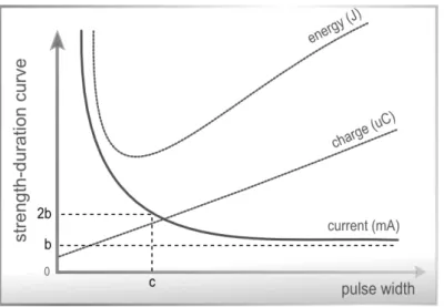
WhereIis the current,brelates to therheobase, andcto thechronaxie, over durationd.
This equation expresses the strength-duration curve (Figure 2.6), which is a plot of the threshold current versus pulse duration required to stimulate excitable tissue. Figure 2.6 also presents the relation of electrical stimulus intensity and duration with stimulation charge and energy.
Figure 2.6: The strength-duration curve for current, energy and charge of an excitable tissue.
2.2.3 Stimulation parameters and physiological impact
As mentioned before, the stimulation parameters applied will condition the respective physiological response, so it is necessary to adapt those parameters to the therapeutic objectives. The cause-effect relation of all the parameters and respective physiological consequences should be known for the correct application of the stimulation.
Amplitude:The amplitude of the stimulation pulse (Figure 2.7) can be measured in
current or voltage, depending on the modulation type. The amplitude determines the stimulation intensity, which consequently determines the total number of nervous fibers that are recruited and activated. As higher the intensity, stronger the depolarizing effect in the structures underlying the electrodes [127]. Higher intensities enable increases in contraction strength and hypertrophy process [62][118][175][143].
Figure 2.7: Amplitude and period of a wave.
Pulse-Width:The time span of a single pulse is known as the pulse-width or pulse
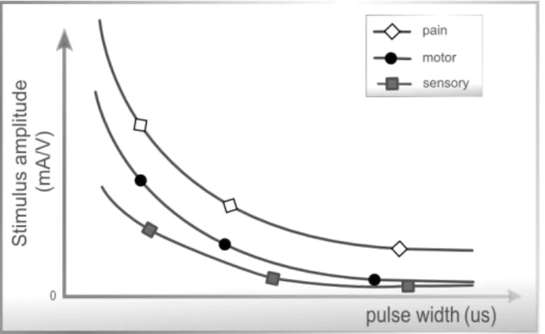
duration. It is defined as the duration of the wave at 50 % of the maximum amplitude, and is expressed usually in microseconds (µs). Research has shown that patients exhibited a strong preference for phase durations of between 200-400µs which are also capable of producing reliable muscle contractions while minimizing the possibility of skin irritation beneath the electrodes [111]. Recent work comparing 50, 200, 500, and 1000µs pulse-widths with a stimulation frequency of 20 Hz to the sole muscle, found that wider pulse-widths produced stronger contractions of plantar-flexion and additionally augmented overall contractile properties [103]. In addition, longer pulse durations will typically penetrate more deeply into subcutaneous tissues, so these widths should be used when trying to impact secondary tissue layers [29]. The pulse-width affects the current amplitude which is necessary to trigger the action potential and also determines the sensitivity of sensory, motor or pain stimulation. Pulsed currents with lower pulse-width are less uncomfortable. As illustrated in Figure 2.8, the sensory, motor and pain sensitivity to stimulation ampli-tudes is maximal when applying pulses with low duration.
However, in this section, it is important to refer an accommodation phenomena [173], which makes the excitability threshold of the nervous tissue adaptive and not absolute. Because of this effect, if the current transfer ratio, which is related to the rise time of the electrical pulse, is longer than several hundreds ofµs, the current amplitude required to reach the action potential will be superior (Figure 2.9).
Figure 2.8: Strength-Duration curves: Relation between amplitude and pulse-width when relating with the influence on excitability thresholds: sensorial, motor and pain tolerance. Adapted from Robertson et al. [154].
Figure 2.9: Relation between the pulse-width applied and the accommodation of the nervous fiber: a) the small current transfer ratio triggers the action potential; b) a bigger current transfer ratio triggers the action potential but showing threshold accommodation; c) the transfer ratio is very high and never surpasses the excitability threshold.
Frequency:Frequency refers to the pulses produced per second during stimulation.
stimulus frequency leads to stronger contractions up to a maximum. However this also increases the rate of muscle fatigue [16][152]. To optimize fatigue, constant low frequency stimulation is used, which produces a smooth contraction at low force levels [21]. How-ever, the muscle fatigue index induced by artificial stimulation is always higher than the voluntary contractions in which the motor neurons activation is triggered asynchronously. The contraction strength is defined by the number of motor units recruited and by the frequency of the action potentials.
In terms of patient comfort, typical NMES stimulator frequencies in the range of 30-60Hz are found to be optimum [111].
Figure 2.10 shows the variation of the fiber strength with the stimulus frequency, for intensities above of the motor limit. A stimulation frequency above 30Hz is indicated for the production of maximum force.
Figure 2.10: Muscular strength variation with the stimulus frequency, for stimulation intensities above the motor limit. Adapted from Kitchen et al. [98].
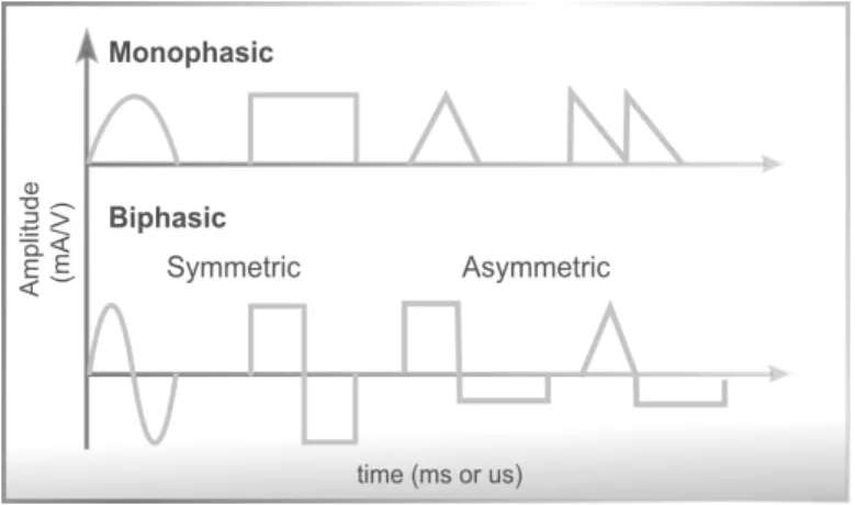
Waveform:In surface electrical stimulation the waveform is the representation of the
variation, over time, of the current or voltage that is injected into the biological tissue. The polarity, in the context of electrical current, refers to the charge way. The pulse may be monophasic (unidirectional / continuous polarity) or biphasic (bidireccional / alternating polarity), as it is represented in Figure 2.11 [66]. The power of the two kinds of current pulses is equal, but if the wave is symmetrical the charge compensation avoids the deposition of ions above the electrodes surface which may cause lesions on the tissue level [140][106].
Figure 2.11: Examples of electric pulses with different polarities and waveforms.
voltage/current with predefined geometric shapes, traditionally the square wave. Figure 2.12 shows a comparison of stimulation waveforms regarding their ability to generate low threshold stimulation, low corrosion, and low tissue damage.
There are a very few studies on the practical effect of the waveform on the physiology response. Durand [56], evaluated the standard waveforms and those studies enabled the compilation of the information present in Figure 2.12. However, there are still various waveforms for which the correspondent biological effect is still unknown. The evaluated parameters by Durand - threshold, corrosion and tissue damage - represent only part of the information about the effect of the waveform on the excitable tissue.
2.3
Application of current
The current is defined as the quantity of electrical charges that goes through a conductor during a determined time interval, i.e. quantity of single charges moving per time unit. According to Kitchen and Bazin [98] the currents can be direct or alternating and pulsed or constant.
In the electrical stimulation scope, the most common types are the direct or alternating pulsed current and the alternating continuous current.
2.3.1 Current Types
For historical reasons, in the clinical perspective, it is usual to identify the applied current, associating it with a name (example: galvanic current, faradic current) and sometimes with a differentiating characteristic or a set of characteristics (example: interferential currents, russian currents). Below are presented the most common nomenclatures in clinical environments:
• Faradic current: A pulsed current with frequencies between 50 and 75 Hz. The
pulses are monophasic or biphasic, with duration of less than 1 millisecond (ms), and are traditionally used for motor stimulation;
• Galvanic Current: A continuous current, usually used for iontophoresis;
• TENS Current:Meaning Transcutaneous electrical nerve stimulation, the TENS
current is used to treat pain. The pulse duration is usually a constant value ranging from 50-200 microsecond (µs) and the pulse frequency is usually adjusted between 2 and 120 Hz;
• Pulsed Current of High Voltage (PCHV):Has a voltage regulated output which
can go up to 500 volts. The stimulus impulse has peaks, has a low duration (ap-proximately 7µs) and the frequency of double pulses combination can vary, usually between 1 and 10Hz.
• Russian Current:An alternating current of 2500 Hz, applied in rectangular bursts
with a burst frequency of 50 Hz and duty cycle of 50 %. The bursts are applied for 10 seconds on, following 50 seconds off, for a treatment period of 20 minutes. The theory inherent to the Russian Current is based on the application of supramaximal intensities to recruit the maximum number of motor units, favoring the hypertrophy process.
intensity. Interferential current is essentially a deeper form of TENS. The high fre-quency carrier waveform penetrates the skin more deeply than a regular TENS unit, with less user discomfort for a given level of stimulation.
• Dynamic Currents:Consists in sinusoidal currents with rectification of half wave
or full wave in the frequency bands of 50 to 60 Hz. As the pulse duration varies between 10 and 8 milliseconds, the stimulation causes high discomfort.
• Microcurrent:It is characterized by a very low intensity current, even bellow the sensory threshold. Its usages include treatments for pain,[1] Diabetic neuropathy,[2] age-related macular degeneration, wound healing, tendon repair, Plantar fasciitis[3] and ruptured ligament recovery.
2.3.2 Transcutaneous stimulation electrodes
In surface electrical stimulation, the application of current is made through surface ad-herent electrodes. For the current to reach underlying tissue, its success highly related to electrode size and placement, as well as the conductivity of the skin-electrode interface [109]. It is important to consider the type and the dimensions of the electrodes.
Self-adhesive electrodes for transcutaneous stimulation use a gel to contact a conduc-tive member with the subject’s skin. This sticker, pre-gelled electrodes are currently used for a better convenience, since they are easy to apply and to remove and don’t require any extra fixations. They already have adhesive gel, inseparable from the surface, being com-pletely disposable - although suppliers provide some types that can be reused in the same patient. The biggest disadvantage of this approach is its cost. There are other electrodes for surface stimulation: metal plates covered with fabric tissue or carbon electrodes. Those have lower cost but are also less practical since they require water or special electrode gel to equally distribute the current over the electrode surface.
The dimensions of the electrode are also an important factor: Bigger electrodes usually mean a higher comfort in the stimulation [1]. Since the current density per area is lower, the stimulation is more effective for sensory stimulation, like pain control, and for motor control. The reaction is stronger since it recruits a bigger amount of motor units [1]. Smaller electrodes will concentrate current densities, allowing for focal concentration of current with less chance of stimulation crossover into nearby muscles [161].
2.3.3 Electrode Placement
• Over the nerve trunk / the muscles motor point;
• In each one of the muscle terminations, so that the nerve is always in the path of the
current.
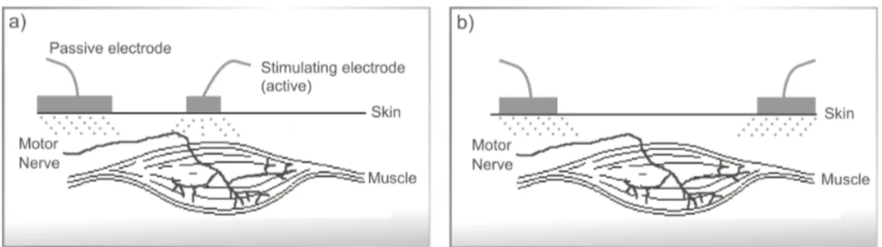
The electrodes positioning is therefore related with its configuration: unipolar or bipolar. The unipolar configuration (Figure 2.13 a) ) uses one active electrode which only transmits current to the passive electrode (that only receives current). In this configuration the active electrode has generally an inferior dimension than the passive. Moreover, in the bipolar configuration (Figure 2.13 b) ) the current flows bidirectionally between both electrodes which, in this configuration usually have the same dimensions, positioned in each of the terminations of the muscle group to be stimulated.
Figure 2.13: Electrodes configuration: a) for unipolar current application; b) for bipolar current application.
The following section describes the most recent circuits used for generic, non-invasive, electrical stimulation purposes.
2.4
Electrical Stimulation Circuits
Independently of the power source, the architecture of current electrical stimulation devices comprise at least an analog module to regulate and drive the current to the tissue, a high voltage module to produce the necessary voltages to overcome the tissue load and a controller unit that can be analog (using for example an oscillator circuit to generate the pulses), or digital (using a microcontroller, offering higher control of the electrical pulse parameters) [44]. Electrical stimulators can be used for specific applications such as the Parastep [146], RGO [171] designed for the lower limbs stimulation; or Freehand [74], Handmaster [131], Bionic Glove [150] for controlling the hand. Another example of specific purpose electrical stimulation devices is the vast list of miniaturized nerve stimulators analyzed in the work of Shariat et al. [162], using low currents, all limited to sensory applications.
there is a limited market access [196][162]. Much of the research in the area of NMES hardware has centered around the use of more sophisticated external sensors, increased number of stimulation channels, flexibility in terms of adjusting the stimulus parameters and new closed loop control techniques to reduce muscle fatigue [16][152].
The state-of-the-art electrical stimulators topologies are described by the scheme of Figure 2.14.
Figure 2.14: Generic configuration of the state of the art stimulators. The Regulation Mode and Stimulation Steering blocks define the Output Stage of the electrical stimulator.
In the following sections the circuit block diagrams, exposed in Figure 2.14, will be individually described.
2.4.1 Micro-controller
Present solutions for electrical stimulation rely on a digital micro-controller device that handles all the peripheral blocks. This module is responsible for managing of the com-munication with the user, handle the high voltage circuit and apply, parametrize and control the stimuli. If it is a portable device, like the one developed in this thesis scope, the micro-controller module will also handle the battery charge and autonomy.
2.4.2 High Voltage
Typical voltages to induce charge transfer to the biological tissue are in the range of 40-200 V. To achieve this range of voltages, using a battery system, thousands of batteries in series would be required. One way of generating those voltages is through the use of standard transformers. Large secondary side voltages may be generated from low primary side transformer voltages. Transformers also have the advantage of providingper sea galvanic
electrical stimulators is out of trend, especially for portable devices [181][44]. A different and recent approach is based on the use of a step-up or boost converter from the class of the switched mode power converters. This circuit is capable of producing an output voltage higher than the input voltage with few components and relative simplicity of design, as shown in Figure 2.15. The efficiency of this circuit will be as higher as the use of the energy generated by the inductor when there are current variations on its terminals.
Figure 2.15: Step-up converter or Boost converter.
2.4.3 Regulation Mode
The regulation block makes the control of the electric energy passed to the tissue load. The stimulator must control one of two variables, voltage or current. Therefore, there are two classes of devices:
• Constant Voltage: These devices regulate the voltage of the electrical stimuli. In
this configuration, the current delivered to the internal tissues is determined by the contact impedance plus the tissue impedance. Any fluctuations that may occur in one of these variables will immediately unbalance the current transferred to the tissue and consequently change the stimulation effect [163][94]. Some implementations of constant voltage stimulators also have a built-in safety system to prevent this effect from causing skin burns due to excessive current density [16][152].
• Constant Current:Constant current devices regulate the stimulation current inde-pendently of the tissue load and contact load variations. For the majority of the applications this implementation will enable a higher consistency between the stim-ulus parameter and the respective effect. This position is consensual among the scientific community [193][160][140][184].
A common circuit to generate constant current stimuli is the current source shown in Figure 2.16. In this circuit the output current can be controlled according to Equation 2.3.
Iout= Vin
(inputsignal)
Figure 2.16: Output stage for a constant current stimulator with a voltage controllable current source.
The operational amplifier (op-amp), actuates in an active feedback, managing the base ofQ1to control the collector and emitter current, equalizing the voltages in the op-amp
inputsVin+andVin−. The current that will flow into the tissue, represented by Load, is
sensed through a sense resistor,Rsense.
An alternative topology for constant current stimulators is presented by Wu et al. [193] and represented on Figure 2.17. In this circuit, two current sources drive the Wilson Current Mirrors. Half circuit is to drive positive stimuli and the other half drives the negative ones. This implementation also needs the use of two High Voltage (HV) power sources, one negative and one positive. The current applied to the skin is given by the nominal value ofR1andR2.
2.4.4 Stimulation Steering
Figure 2.17: Output stage for constant current stimulator with two high voltages sources and two Wilson current mirrors [193].
the use of centered referenced transformers. With two distinct coils on the secondary, it is possible to generate two independent power supplies. This implementation is not very common, for reasons already explained previously, in the generation of high voltages, given the required size and inefficiency.
The most common method currently used for biphasic impulses generation is the polarity commutation, as exemplified in Figure 2.18 [31][100][165]. This is the simplified version of a common circuit for current commutation, and it is known as H-bridge. It belongs to the class of constant voltage and enables the application of biphasic pulses with the correct setting of the transistorsQ1,Q2,Q3andQ4that act like a switch.
Figure 2.18: Representation of a typical current steering output stage.
C
H
A
P
T
3
P
ROPOSED
S
OLUTION
The answers to the previously raised questions represent important contributions to achieve new goals and knowledge in the electrophysiological field. The challenges raised by these questions are inaccessible with current market technology. In this regard, it is necessary to develop new methodologies for non-invasive human electrical stimulation. In this chapter, the main steps in the development of an electrical stimulator with reliable temporal synchronization with a biosignal acquisition system are described. All the device’s modules and their operation are depicted, as well as the configuration and control software and the device’s mechanical components.
3.1
Requirements
The first development stage of any solution is an effective requirement analysis. The requirements for this project were defined as a set of functional, technical, usability and other characteristics that make it possible to answer the scientific questions previously raised.
3.1.1 Functional and Technical Requirements
In order to achieve an efficient operation in the wide contexts of electrical stimulation, during the device design plan, some functional characteristics were defined. Those charac-teristics are enumerated below.
1. Parametrization:The electrical stimulator should allow to completely parametrize


![Figure 2.17: Output stage for constant current stimulator with two high voltages sources and two Wilson current mirrors [193].](https://thumb-eu.123doks.com/thumbv2/123dok_br/16541282.736741/55.892.210.726.125.631/figure-output-constant-current-stimulator-voltages-sources-wilson.webp)

