Development of a Dynamic Path for a Toxic
Substances Mapping Mobile Robot in Industry
Environment
Luis Piardi1,2
, Jos´e Lima2,4
, Paulo Costa3,4
, and Thadeu Brito1,2
1
Federal University of Technology - Paran´a, Brazil
luis [email protected],
thadeu [email protected]
2
Polytechnic Institute of Bragan¸ca, Portugal
3
Faculty of Engineering of University of Porto, Portugal
4
INESC-TEC, Centre for Robotics in Industry and Intelligent Systems, Portugal
Abstract. Some industries have critical areas (dangerous or hazardous) where the presence of a human must be reduced or avoided. In some cases, there are areas where humans should be replaced by robots. The present work uses a robot with differential drive to scan an environment with known and unknown obstacles, defined in 3D simulation. It is important that the robot be able to make the right decisions about its way without the need of an operator. A solution to this challenge will be presented in this paper. The control application and its communication module with a simulator or a real robot are proposed. The robot can perform the scan, passing through all the waypoints arranged in a grid. The results are presented, showcasing the robot’s capacity to perform a viable trajectory without human intervention.
Keywords: Simulation, mobile robotics, path planning
1
Introduction
The new paradigms of industry demand the collaboration between robot and humans. It is desired that both could help each other and also to collaborate. The impact on Industry 4.0 and Cyber-Physical Systems is a new technical systems paradigm based on collaboration [1] and will contribute to several areas, such as, new value chain models in industry, human security, efficiency, comfort and health, among the others. Some industries have critical areas where the presence of a human must be reduced or avoided. In these cases, there are some danger or hazardous areas where humans should be replaced by robots.
This paper presents an approach that can be used to scan a dangerous area in an industry. It is composed by a planning method that routes the path avoiding the known obstacles and also re-plan, on the fly, avoiding previously unknown obstacles that are detected by Time off Flight sensors, during the scanning pro-cess. It is also presented a simulation environment that allows to test and val-idate the proposed approach and algorithms. Further, these algorithms will be implemented in a real robot and the toxic mapping task will be done in a real environment. Due to some confidential issues, the company name, photos and toxic elements are omitted. Nevertheless, the layout of the mapping area of the simulation environment is presented in Figure 1.
Fig. 1: Layout of the scanning area in simulation environment.
The remaining of the paper is organized as follows: after a brief introduction in this section, the state of the art of path planning is addressed in next section. Section 3 presents the system architecture where the communication between different modules and the robot model are stressed. The connectivity grid, the path planning and robot control are presented in section 4 whereas section 5 shows the results. Finally, section 6 rounds up the paper with conclusions and points some future work direction.
2
Related work
Dynamic Path Mapping Robot for Industry Environment 3
2.1 Planning
The classic travelling salesman problem (TSP), regarding a group of n cities, where the purpose of this problem is to start the route in city defined, visiting the other cities only once, and them returning to the first city [2]. Considering the possibility of the existence of several cities, the TSP becomes complex with (n−1)! possible routes to be calculated. The work of Pereira et al. [3] presents a problem with characteristics similar to the TSP, where they seek to determine the most efficient way to collect golf balls scattered through an open field using a robot with differential drive.
Similar to the TSP is the scanning of a room with toxics substances as addressed in the present work. Using a connectivity grid with standard space between each point or distributed points configurable by user, the robot needs to find an optimal path between the starting and the destination point, crossing all points of the grid while avoiding repeat points. Moreover, obstacle avoidance should also be performed.
For robot navigation and scanning, Hirakawa et al.[4] presents research us-ing the Adaptive Automaton theory to model, identifyus-ing and classifyus-ing the robot decision. Our work presents a similar approach, where we seek to find the next movement of the robot in the exploration process, with four options of movements: north, south, east, west. It is possible to modify the decision due to the existence of unmapped objects, which are detected based on a Time of Flight sensor (ToF). There is a great deal of effort by the academic community in researching path planning, where they use different approaches such as Rapidly-exploring Random Tree [5], Road Map [6], Cell Decomposition [7], Potential Field [8], and others.
2.2 Trajectory
Many works with mobile robotics use smooth curves because they are performed by robots with non-holomonic constraints. The B´ezier curves are an example. As presented in the works [6, 9, 10], the robots can perform the B´ezier curves autonomously. However, this approach, despite implementing a smooth curve, does not require the robot to pass over at all points. It is only an approximation to the points, which is not interesting for the mapping of toxic substances inside a room or industry.
Magid et al. [8] use potential field for path planning. For building a smooth curve, they use splines in order to pass at all points and avoid obstacles [8]. In our approach, we will use an improved splines approach so that the curve performed by the robot is smooth and also precise on the waypoints.
3
System Architecture
3.1 Robot
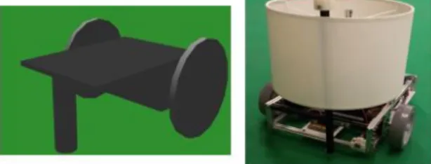
wheel can independently be driven either forward or back-ward. By this way, it is possible control the speed and rotation of the robot. The real robot was also developed as presented in right side of Figure 2 whereas left figure shows the robot developed in a realistic simulation system, the SimTwo. Further expla-nations about the implementation and use of this software can be seen in [11, 12]. The real robot will be used in future works for the toxic mapping after the validation through the simulation of the approach presented in this work.
Fig. 2: Model of simulated robot at left and the real robot at right.
3.2 Communication Between the Simulator and the Application
For this project, it was used two different environments. The first one (ControlApp) is an application, developed in Lazarus, that interfaces the user and controls the robot, based on its position (x,y,θ) provided by the second one, the SimT woa 3D simulated environment.
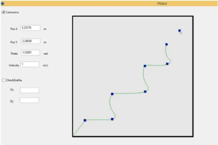
TheControlApphas an interface for the user to interact with the robot. It provides to the operator the speed, position and orientation of the robot in real-time. Moreover,ControlAppshows an image that represents the environment of the robot. The interface is shown in the Figure 3.
The operator can control the robot through two methods. The first one, user can insert the waypoints, clicking with the mouse on the image in the desired position. The second method computes a grid of waypoints by selecting thedx
anddyas the distance of waypoints inxandydirection. Then, it is automatically inserted a grid of possible waypoints according to the values input by the user.
TheControlAppis responsible for all processing that involves the robot, such as calculations for the spline trajectory and planning, calculations for the control of the speed of the wheels and recalculating a new route when an unmapped obstacle is detected.
In the simulation environment, the physical structure of the robot is defined as width, weight, length, thickness, size and position of the wheels and sensors. The motor and sensors simulation models are addressed in previous works [13– 15].
Dynamic Path Mapping Robot for Industry Environment 5
Fig. 3: Interface of Lazarus application,ControlApp.
Fig. 4: SimTwo simulation 3D environment.
The communication between both applications is based on a UDP/IP net-work protocol. A packet encoding the robot position, orientation and distance sensor data is sent from theSimT woto theControlApp, whereas a packet con-taining the right and left speed wheels is sent fromControlAppto theSimT wo, as presented in Figure 5.
4
Application Development
With intention of to replace human presence by robots in high risk environ-ments (dangerous industrial environment), it is necessary that such robots are autonomous. Robots must have the ability to check unmapped obstacles and make efficient decisions without the help of human. On the other hand, the Hu-man Machine Interface (HMI) is necessary to perform some configurations, such as waypoints, grid accuracy, speeds and visualization.
4.1 Connectivity Grid
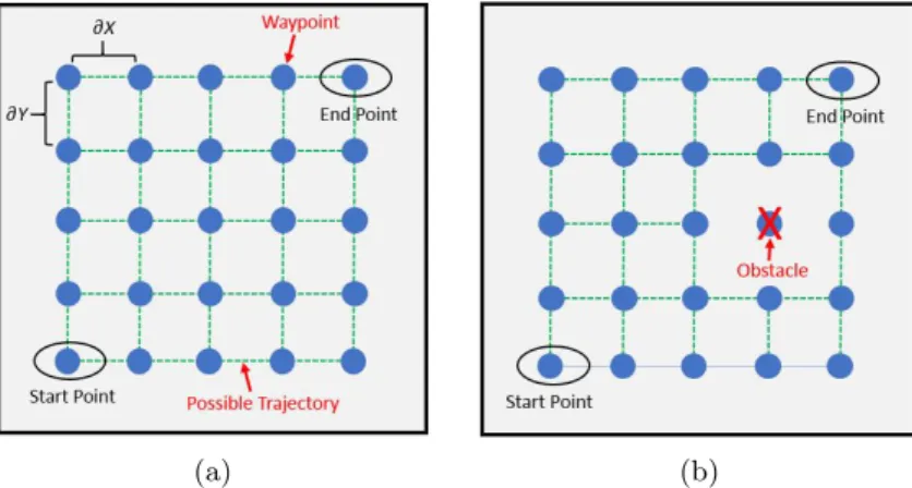
The connectivity grid is an approach used for the robot to scan all desired areas of a room or environment, considering the distance between the waypoints defined by the user. This grid will establish all the possible trajectories for the robot. Figure 6a shows a connectivity grid for a environment with 3 meters length and width and the waypoints with a distance of 0.5 meters (dx,dy).
(a) (b)
Fig. 6: (a) Connectivity Grid. (b) Connectivity grid with the presence of obstacle.
The robot is constrained to perform only horizontal or vertical trajectories in the north, south, east and west directions (no diagonal trajectories). Initially a mapped object existence is verified. If a mapped object is verified, the waypoint that intercepts this object is excluded from the connectivity grid and, as a result all trajectories that provide access to this point are excluded. Figure 6b illustrates the effect of an obstacle on the connectivity grid. Based on this condition will be projected the path for the robot to reach the end point and crossing all available waypoints.
Dynamic Path Mapping Robot for Industry Environment 7
(avoiding a collision with the unmapped obstacle) while plans a new route, thus eliminating the point where there is an obstacle. With this algorithm the robot will go through all the waypoints until reaching the end point and avoiding obstacles.
4.2 Robot Controller
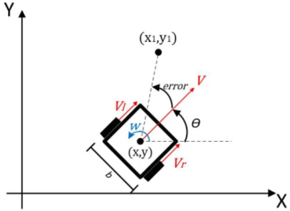
Robot controller uses the kinematics model of the robot. It receives the position (x,y,θ) from the simulator and then controls the speed of the right and left wheel (VrandVl). In simulation environment,SimT wois responsible for the dynamics presents in the system, since it uses the ODE (Open Dynamics Engine) library for simulating rigid body dynamics [12]. Figure 7 shows an outline of the robot and represents the characteristics of its movement along a room considering the speed of the robot’s wheels.
Fig. 7: Considerations for calculating the linear velocity of the robot wheels.
SinceV is the linear velocity,wis the angular velocity of the robot (δθ δt) and b is the distance between wheels of the robot, we obtain the equation 1.
V =Vl+Vr
2 ; w=
Vl−Vr
2 (1)
For the orientation of the robot to the next point of its trajectory, the value ofw must follow a reference (wref) in function of a constant of proportionality (Kp) and error between the robot orientation and trajectory. The velocity V must be constant (Vref) as shown in equation 2 and complemented by Figure 7. The coordinate (x, y) indicates the actual robot position and (x1, y1) represents the coordinates of the next robot trajectory point.
Vref =K1 ; wref =Kp·error (2)
Finally, the velocity of wheels can be calculated by equation 3.
Vl=Vref −wref · b
2 ; Vr=Vref+wref · b
4.3 Trajectories Defined by Splines
Splines in two-dimensional space were used in this work to represent the trajec-tories performed by the robot. The trajectory is the path that the robot follows between two distinct waypoints. The total path that the robot will perform, from the starting point until reaching the end point is divided into several trajectories, which will depend on the layout of the mapped and unmapped obstacles. Forn waypoints there are n−1 trajectories.
The implemented algorithm calculates a cubic spline for the mathematical representation of the trajectories(calculations and mathematical proofs can be found in chapter 18 section 6 of the book [16]), which are feasible by the robot. It’s purpose is to smooth the trajectory that connects the waypoints through a third degree function.
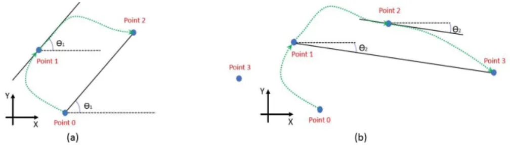
To ensure a smooth curve, the angle of entry into a waypoint should be the same as the angle of exit. The implemented algorithm determines this angle as a function of the slope of the straight line defined by the waypoint that precedes and succeeds the point in question.
Fig. 8: Trajectory defined by Spline. The green curves indicate the trajectories to be followed by the robot. The black lines indicate the angle of entry and exit of the waypoints.
Figure 8a represents the calculation for the entry and exit angle of point 1, whereas Figure 8b represents the estimate for waypoint 2. Equation 4 describes the calculation to determine the angle.
θi=atan2(yi+1−yi−1, xi+1−xi−1) (4)
4.4 Path planning considering the grid of connectivity
Dynamic Path Mapping Robot for Industry Environment 9
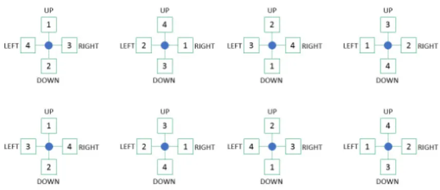
The algorithm checks which waypoint adjacent to the current waypoint was less visited by the robot. If only one waypoint was less visited, the robot will move to it. When the smallest number of visits is verified in more than one adjacent waypoint, the choice will be the one of these least visited waypoints according to the current priority of the robot’s trajectory (Figure 9). This algorithm is used for all eight priorities. Switching from one priority to the next occurs when the algorithm finds the final waypoint and all other waypoints have been visited at least once. When the eight priorities are finalized, the one with the shortest path will be selected.
If an obstacle is detected, the waypoint that intercepts the obstacle will be deleted as well as the possible trajectories as shown in Figure 6b. Then, the algorithm calculates a new route in the same way as described above. However it will take into consideration the points already visited as well as the waypoints that can not be visited due to the existence of obstacles.
Fig. 9: Priority of robot trajectories.
5
Results
In order to validate the developed application, some tests were accomplished using theSimT wosimulator and theControlApp.
5.1 Result of trajectory spline
Fig. 10: Result of the spline trajectory algorithm.
5.2 Result of the planning algorithm applying a grid of connectivity.
With the objective of analyzing the path planning and a grid of connectivity with obstacles, three tests were made in a simulation environment with 3 meters width by 3 meters height having a spacingdxanddyof the connectivity grid of 0.35 meters for all tests performed below. The identification of mapped obstacles is highlighted through the red color inSimT wosimulation andControlAppand the identification of unmapped obstacles is highlighted through the purple color in SimT wosimulation andControlApp.
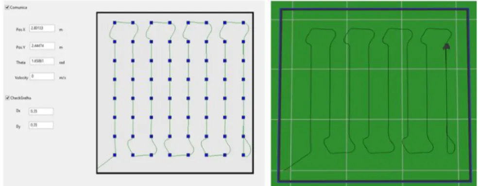
Result of the path planning in environments without obstacles: The algorithm for the path planning is executed only once because there are none obstacles in the environment and having an outstanding result. The robot (starts at left bottom corner) explored the entire room through all the waypoints present in the first seven columns of the connectivity grid only once. In the eighth column the robot passed twice in each waypoint to reach the end point (right upper corner) as Figure 11 shows. Given the proximity of waypoints, this case does not have the concavities of the curve well defined as in the example presented in the Figure 10.
Dynamic Path Mapping Robot for Industry Environment 11
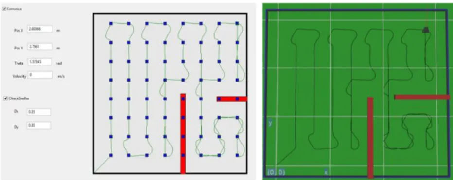
Result of the path planning in environments with mapped obstacles:
The Figure 12 presents mapped obstacles simulating a room, having only a sin-gle path for entry or exit. The waypoints that are in the regions of the mapped obstacles are excluded from the connectivity grid before executing the path plan-ning algorithm, i.e., only waypoints free of obstacles will be computed for path planning. Consequently the algorithm is executed once. The results for this robot path planning validates the approach, since to complete the planning, the robot will pass a maximum of two times in each waypoint.
Fig. 12: Result of planning algorithm with mapped obstacles.
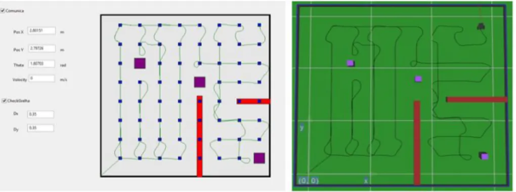
Fig. 13: Result of planning algorithm with mapped and unmapped obstacle.
6
Conclusion and Future Work
This paper presents a system for explorer and scanning a dangerous area in an industry, where the presence of humans should be reduced. The planning method that routes the path avoiding the known and unknown obstacles that are detected by ToF sensors during the mapping process is implemented in a simulation environment. The results are convincing since the robot maps the selected waypoints, introduced by user or grid.
As future work, the replacement of theSimT wo by the real robot (already developed) will be done. Once the protocol communication betweenControlApp andSimT wo will be adopted by the real robot, this task is simplified.
Acknowledgment
Project ”TEC4Growth - Pervasive Intelligence, Enhancers and Proofs of Con-cept with Industrial Impact/NORTE-01-0145-FEDER-000020” is financed by the North Portugal Regional Operational. Programme (NORTE 2020), under the PORTUGAL 2020 Partnership Agreement, and through the European Re-gional Development Fund (ERDF).
This work is also financed by the ERDF European Regional Development Fund through the Operational Programme for Competitiveness and Internation-alisation - COMPETE 2020 Programme within project POCI-01-0145-FEDER-006961, and by National Funds through the FCT Funda¸cao para a Ciˆencia e a Tecnologia (Portuguese Foundation for Science and Technology) as part of project UID/EEA/50014/2013.
References
Dynamic Path Mapping Robot for Industry Environment 13
2. Miller, C.E., Tucker, A.W., Zemlin, R.A.: Integer Programming Formulation of Traveling Salesman Problems. In: Jornal of the ACM, vol. 7, Issue 4, pp. 326–329, New York (1960).
3. Pereira, N., Ribeiro, F., Lopes, G., Whitney, D., Lino, J.: Autonomous golf ball pick-ing robot design and development. In: Industrial Robot: An International Journal, vol. 39, Issue 6. pp.541–550 (2012).
4. Hirakawa, A. R., Saraiva, A. M., Cugnasca, C. E.: Autˆomatos Adaptativos Aplicados em Automa¸cao e Robtica(A4R). In: IEEE LATIN AMERICA TRANSACTIONS, vol. 5, Issue 7. pp. 539–543 S˜ao Paulo (2007).
5. Vaz, D.A.B.O., Planejamento de movimento cinem´atico-dinˆamico para robˆos mveis com rodas deslizantes. Universidade de S˜ao Paulo (2011).
6. Yang, X., Zeng, Z., Xiao, J., Zheng, Z.: Trajectory planning for RoboCup MSL mobile robots based on B´ezier curve and Voronoi diagram. In: IEEE International Conference on Information and Automation. pp. 2552–2557 (2015).
7. Kloetzer, M., Mahuela, C., Gonzalez, R.: Optimizing cell decomposition path plan-ning for mobile robots using different metrics. In: 19th International Conference on System Theory, Control and Computing (ICSTCC). pp. 565–570 (2015).
8. Magid, E., Karen, D.,Rivlin, E., Yavneh,I.: Spline-based robot navigation. In: IEEE/RSJ International Conference on Intelligent Robots and System. pp. 2296– 2301 (2006).
9. Hwang, J.H., Arkin, R.C., Kwon, D.S.: Mobile robots at your fingertip: Bezier curve on-line trajectory generation for supervisory control. In: IEEE/RSJ International Conference on Intelligent Robots and Systems. pp. 1444–1449 (2003).
10. Simba, K.R., Uchiyama, N., Sano,S.: Real-Time Trajectory Generation for Movile Robots in a Corridor-Like Space Using Bezier Curves. In: IEEE/SICE Int. Symp. Syst. Integr. pp. 37–41 (2013).
11. Costa, P., Gon¸calvez, J., Lima, J.: SimTwo Realistic Simulator: A Tool for the Development and Validation of Robot Software. In: Int J Theory Appl Math Comput Sci. pp. 17–33 (2011).
12. Nascimento, T. P., Moreira, A. P., Costa, P., Costa, P, Concei¸c˜ao, A. G. S.: Mod-eling Omnidirectiona Mobile Robots: An Approach Using SimTwo. In: 10th Por-tuguese Conference on Automatic Control, pp. 117–223. Funchal (2012).
13. Lima J., Gon¸calves J., Costa P., Moreira A.: Modeling and Simulation of a Laser Scanner Sensor: An Industrial Application Case Study. In: Azevedo A. (eds) Ad-vances in Sustainable and Competitive Manufacturing Systems. Lecture Notes in Mechanical Engineering, pp. 697–705. Springer, Heidelberg (2013).
14. Lima J., Gon¸calves J., Costa P.: Modeling of a Low Cost Laser Scanner Sensor. In: Moreira A., Matos A., Veiga G. (eds) CONTROLO2014 Proceedings of the 11th Portuguese Conference on Automatic Control. vol 321. pp. 697–705. Springer, Cham (2015).
15. Gon¸calves J., Lima J., Costa P., Moreira A.: Modeling and Simulation of the EMG30 Geared Motor with Encoder Resorting to SimTwo: The Official Robot@Factory Simulator. In: Azevedo A. (eds) Advances in Sustainable and Com-petitive Manufacturing Systems. pp.307–314. Springer, Heidelberg (2013).